 |
Chapter
Four
LIGHT
SYSTEM CONFIGURATIONS
Whether
you are sending a simple on
and off signal or high-speed
computer data, some kind of
light
path
must be establish between
the light transmitter and
the distant receiver. The
three basic ways
the
information can be transferred are:
"Opposed", "diffused reflective" and
"retro reflective".
Every
communications
system will use one or more of
these methods.
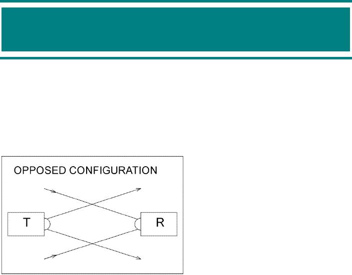
Opposed
Configuration
As
illustrated in Figure
4a an
"opposed"
or
"through beam" configuration points
the
light
transmitter and the receiver
directly
at
each other. Although much of
the light
launched
by the transmitter may
never
reach
the distant receiver
assembly,
sufficient
light is detected to
pass
information.
Since there is only
air
between
the transmitter and receiver, it
is
the
most commonly used
configuration to
transmit
information over long
distances.
Most
optical communications systems
rely
on
this configuration. Remote
controllers
for
televisions, VCRs, audio systems
and
computers
all rely on this direct
light link
method,
since it makes the most
efficient
Figure
4a
use
of the transmitted
light.
As
the light emerges from
the end of the transmitter it
immediately begins spreading out. The
light
forms
a cone shaped pattern of illumination.
The spreading out of the
light beam means the
area
being
illuminated at the distant
receiver will always exceed
the receiver's light
collecting area. The
light
that does not actually
strike the receiver assembly
is therefore lost. If you
tried to design a
system
so all the launched light
hit the receiver, you
would soon discover that it
would be
impossible
to maintain proper alignment.
Small vibrations, building
sway and even air
disturbances
could
bend the light beam enough
to miss the receiver assembly
altogether. An intentional
over-
illumination
scheme works the best, since
it allows for some
misalignment without the
complete
loss
of the light signal. When
designing a system using an
opposed configuration you can
use the
range
equation discussed in the
last section as a way of
predicting how much light
will strike the
receiver,
how much light power
needs to be launched and what
kind of divergence angle is
needed
to
establish a communications link
over a specified distance.
Page
33
of 68
Optical
Through-the-Air Communications Handbook
-David A. Johnson, PE
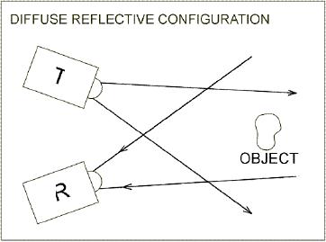
Diffuse
Reflective Configuration
When
you look at the stars at
night, car headlights or at the
sun, your eyes collect
the light that is
coming
directly from the light
source. When you look at the
moon, a movie screen or when
you
look
at the light reflected off
walls from a table lamp,
you don't see the source of
the light, but
the
light
that happens to reflect off
the object being illuminated
by the source. Unless the
object has a
mirrored
surface, the light that
strikes the object spreads
out in all directions. The
light that you
see
is
only a very small portion of
the total light that
actually illuminates the
object. This "diffuse
reflective"
configuration, as shown in
Figure
4b is a
technique that is very
useful in
some
communications systems. It is
especially
good for short distances
when
multiple
reflections allow the
light
receiver
to be aimed, not at the
light
source
directly, but at objects
being
illuminated
by the source. Some cordless
stereo
headsets use such a method
to
give
a person some freedom
of
movement
as he listens to music. These
systems
bounce the light off
the walls,
ceilings
and floors with sufficient
power
that
enough light finds its
way to a light
detector
attached to the headset, no
matter
how the headset detector
is
oriented.
Figure
4b
The
amount of light detected by
the receiver is very dependent on
the nature of object's
surface that
reflects
the light. As an example,
walls painted with white
paint will reflect more
light than those
painted
with dark paint. Also,
rough surfaces will tend to reflect
less light than smooth
surfaces.
Most
surfaces reflect the light in a
hemispherical pattern with
more light being bounced
straight
back
toward the light source then
off to the sides. When
you are trying to predict
the behavior of
such
reflections it is best to think of
the area of illumination as an
independent light source that
has
a
90-degree half-angle divergence
pattern. Then, if you know
the acceptance angle of the
light
receiver
and its collection area, you
can use the range equation to
calculate how much of the
total
light
reflected will be collected by the
light receiver.
If
a single surface reflection is to be
used, it is best to try to
illuminate the smallest area
possible.
This
concept can be illustrated by imagining
how your eyes respond better
to a brightly lit spot
reflected
off a wall than to a broad
floodlight. By concentrating most of
the light onto a small
area
more
light will be reflected back to a nearby
receiver that is aimed at the
illuminated area.
However,
when
multiple reflections are desired,
such as done with the stereo
headsets, a small or
large
illuminated
area will work just about
the same. In detecting light
from single reflections you
should
plan
to use a large collection
area, with a small
acceptance angle. The
receiver would be aimed
directly
at the illuminated spot.
However, for multiple
reflection applications it is best to
use a
detector
with a very wide acceptance
angle. Detectors using large
lens collectors will have
little
effect
in multiple reflection cases, since
they would have narrow
acceptance angles.
As
food for thought, it may be
possible to use fluffy white clouds as
diffuse reflectors to link
two
distant
light transceivers. Some
preliminary test results indicate
that such a scheme may be
possible
Page
34
of 68
Optical
Through-the-Air Communications Handbook
-David A. Johnson, PE
if
a transmitter, using a narrow
light beam, launches
sufficient light power and an
equally efficient
light
receiver with a large light
collector is used. Such a
method may be very useful in
allowing one
powerful
transmitter to be received by multiple
light receivers that do not
have a direct
line-of-sight
path
to the transmitter. The
imagined scheme might resemble
the bright search lights
often used to
attract
people to some gala event. Even
the tiny amount of light
reflected off dust particles
in the air
allow
you to see the search
light beam moving up toward
the clouds many miles
away. This concept
would
be a great area for an experimenter to
try to see if such a system
could actually be made
to
work.
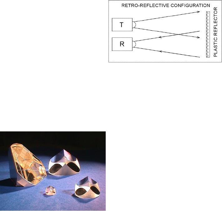
Retro
Reflective Configuration
As
illustrated in Figure
4c if a special
mirror reflector, called a
"corner cube" reflector, is
used to
bounce
light from a transmitter to a
nearby light receiver, the
light transmitter and receiver
are
said
to be linked using a "retro
reflective"
configuration.
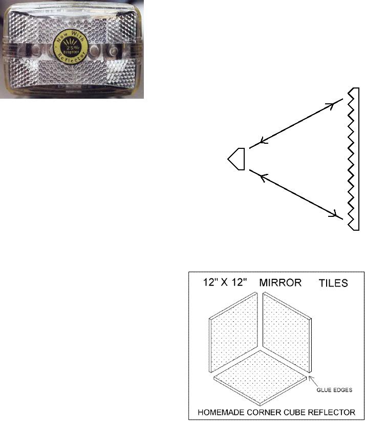
A corner cube reflector can
be
made from a specially ground
piece of
glass,
as shown in figure
4d or
from
positioning
three mirrors at right angles
to
each
other as shown in figure
4d-3.
Some
plastic
reflectors often used on
bicycles
and
roadside indicators are
actually large
arrays
of miniature molded corner
cube
reflectors
(see figure
4d-1). A corner
cube
has
the unique characteristic
that will
return
much of the light striking
the
Figure
4c
assembly
directly backs to the light
source
in
a parallel path, independent of
the position of the emitter.
However, because of the
parallel path,
the
light transmitter and receiver
must positioned very close to
each other. Some very
accurately
made
corner cube reflectors send
the light back in a path
that is so parallel that the
light receiver
must
actually be placed inside the
light transmitter to properly detect
the light being
returned.
Corner
cube reflectors have a wide
variety of
applications.
Several highly accurate corner
cube
arrays
were left on the moon
during some of the
Apollo
moon missions in the early
1970s.
Scientists
have been using powerful
lasers and
specially
modified telescopes to bounce
light off
of
the reflectors. By measuring
the time the
light
pulses
take to make the round trip
from the earth,
to
the moon and back, the
distance can be
measured
down to inches. Electronic
distance
measurement
devices (EDMs), used by
survey
crews,
also use corner cubes and
"time of flight"
techniques
to measure distances accurate to
inches.
Some systems have effective
ranges of
several
miles. Remember, light
travels about one
foot
in one nanosecond, so for a round trip
of
10,000
feet would cause a pulse
delay of 10,000
Figure
4d
nanoseconds
or 10 microseconds.
Page
35
of 68
Optical
Through-the-Air Communications Handbook
-David A. Johnson, PE
Some
alarm systems also use the
retro-reflective technique. Pulsed light
is bounced off a
distant
plastic
reflector and is collected by a nearby
light receiver. Objects
moving between the
light
transmitter
and the reflector break the established
light path, setting off
the alarm. Some
industrial
systems
also use the technique to
monitor products moving down
a production line.
You
can increase the effective
corner cube size by placing
a
fresnel lens in front of the
corner cube as shown in
figure
4d-2. Using
the technique, you can make a
one
inch
diameter glass corner cube
appear to be several
feet
in
diameter. This technique can
dramatically lower
the
overall
cost.
Figure
4d-1
SMALL
When
using the retro reflective
technique you have
CORNER
CUBE
to
treat the reflector as a
distant light source with
its
own
emitting area and divergence
angle. The
amount
of light sent back by the reflector
will
depend
on the ratio of the
illuminated area and
the
reflector's
area. A typical plastic
reflector has an
equivalent
divergence angle of about
0.5 degrees.
For
long-range applications a large
reflector will be
needed.
Figure
4d-3 shows a
large corner cube
reflector
LARGE
FRESNEL LENS
you
can make yourself. Gluing three
glass tile
Figure
4d-2
mirrors
together makes it.
A sturdy
cardboard
box will help position the
mirrors.
One
mirror is positioned at the
bottom of the
box
and the other two converge
at the box
sides.
You would align such an
assembly so
the
light would enter at a
30-degree angle
relative
to the bottom. The target
for such an
assembly
would be the point where
the three
mirrors
converge. I have used such a
simple
mirror
for some experiments and was able
to
detect
reflections over a distance of 10
miles.
Larger
mirror assemblies or even
multi-
reflector
arrays are also possible to
increase
the
effective range. Perhaps you
might
experiment
with your own large
reflector to
see
if a long range distant measuring
systems
could
be devised. Using two such
reflectors
it
might be possible to pinpoint your
location
Figure
4d-3
using
triangulation techniques.
Page
36
of 68
Optical
Through-the-Air Communications Handbook
-David A. Johnson,
PE
Table of Contents:
- LIGHT THEORY:The Spectrum, Human Eye Response, Silicon Detector Response
- LIGHT DETECTORS:The Silicon PIN Photodiode, Active Area, Response Time
- LIGHT EMITTERS:Light Emitting Diodes (LEDs), Solid State Semiconductor Lasers
- LIGHT SYSTEMS CONFIGURATIONS:Opposed Configuration, Diffuse Reflective Configuration
- LIGHT PROCESSING THEORY:Lenses as Antennas, Light Collimators and Collectors
- OPTICAL RECEIVER CIRCUITS:Current to Voltage Converter Circuits, Post Signal Amplifiers
- OPTICAL TRANSMITTER CIRCUITS:Audio Amplifier with Filters, Pulsed Light Emitters