 |

Chapter
Five
LIGHT
PROCESSING THEORY
Lenses
as Antennas
There is a
reoccurring analogy between
optical communications and radio.
Both systems use
similar
components
that, although made from
completely different materials,
perform similar functions.
As
an
example, a radio system will
always use some kind of
antenna to capture the
diffuse and often
weak
signals from the air.
Optical systems use similar devices in
the form of lenses or
mirrors to
gather
the weak light signals
for processing. Large antennas or lenses
will allow weaker signals
to
be
detected.
In
microwave radio communications,
such as satellite receivers,
the antenna is often a
specially dish
shaped
metal reflector. The
microwave signals are
bounced off the dish
surface and are
concentrated
at its focal point, where
they can be more efficiently
amplified. Similarly, mirrors
can
be
used in optical telescopes or
some optical communications systems to
collect light and focus
it
onto
special light detectors.
In
much the same way
that the incoming radio or
light signals are processed,
the outgoing signals
can
also benefit from specially
shaped antennas or lenses. The radio or
light source, when
positioned
at the focal point of a
reflector, can shape the
outgoing signal into a
narrow beam. The
larger
the antenna or lens, the
narrower the beam becomes. A
narrow light beam insures
that more
of
the desired signal is
directed toward the distant
receiver for better
efficiency.
Mirrors
and Lenses
Although
you can use mirrors in
through-the-air communications, lenses
are more often
used.
Lenses
are usually much cheaper,
readily available and much
easier to align than
mirrors. Useful
lenses
can be found in hardware stores, bookstores,
office supply stores and
even grocery stores. All
of
the discussions in this book will
center on the use of lenses,
although some of the
techniques used
for
lenses can also be applied to
mirrors.
Types
of Lenses
Most
of the lenses used in
through-the-air communications have one
or two outwardly
curved
surfaces.
Such lenses are called
"convex" lenses. Small glass or
plastic lenses are great for
short-
range
applications. However, glass
lenses larger than about 3
inches become too heavy
and
expensive
to be practical. Beyond the
3-inch size it is best to use a
flat or "Fresnel" lens.
Fresnel
lenses
can be purchased with diameters ranging
from one to more than 36
inches. These lenses
are
made
from molded plastic sheets
that have small concentric
grooves on one side. When
viewed
close-up,
they look like the
grooves in a phonograph record. These
lenses are very
carefully
designed
to bend the light just as a
convex lens would. When
using a Fresnel lens always
remember
to
keep the grooves pointing
toward the outside, away
from its focal point.
Using the lens in
reverse
will
result in lost light and a
poor image.
Page
37
of 68
Optical
Through-the-Air Communications Handbook
-David A. Johnson, PE
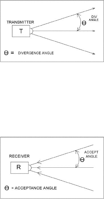
Divergence
Angle
The
outgoing light from an
optical transmitter forms a cone
shaped area of illumination
that spreads
out
from the end of the
transmitter. As illustrated in
Figure
5a the
specification that
mathematically
describes
the spreading out of the
light is
called
the "divergence angle". It is
almost
always
described as a half angle or
the
angle
from the center axis of
the
illumination
cone. Often the edge of
the
illumination
cone is defined as the
1/2
power
point, relative to the
center light
intensity.
To help illustrate the
concept,
imagine
a flashlight whose beam can
be
adjusted
from a broad flood to a
bright
spot.
The bright spot would have a
smaller
divergence
angle than the flood.
Likewise,
a
red laser pointer would be an example
of
Figure
5a
light
source with a very narrow
divergence
angle.
If you have ever had a chance to
play with as laser pointer,
you would have noticed
that the
beam
does not increase
appreciably in size as it strikes a wall
across a room. Such
divergence
angles
can be so tight, that keeping
the spot on a distant target can be
nearly impossible.
Most
optical
communications systems therefore
purposely allow the beam to
diverge a little so
optical
alignment
can be easily maintained.
Acceptance
Angle
The
incoming light, focused onto
a light detector, also has a
restricted cone shaped area
of
collection.
Light striking the lens,
outside the cone area, will
not be focused onto the
detector. As
illustrated
in Figure
5b, the
incoming
angle
is called the "acceptance angle"
that
is
also defined as a half angle. To
help
illustrate
this concept, imagine
looking
through
a long and a short section of
pipe.
Even
if the two pipes have
the same
diameter
the long pipe will restrict
the
field
of view more than the
shorter pipe.
Pipes
that are specially made to
restrict the
field
of view are often used to
help aim an
optical
system and are referred to as
"bore
sights"
(see Figure
5c.) As in
divergence
angles
that are too small, an
acceptance
Figure
5b
angle
should also not be too
narrow or you
will
have problems in maintaining
alignment with the distant
transmitter.
Light
Collimators and Collectors
The
light, bent by a lens as it leaves a
transmitter, is said to be "collimated".
As illustrated by
Figure
5d, lenses
used to collimate the
emitted light from sources
such as LEDs, should
be
carefully
selected for their diameter
and focal length. A lens
with a focal length that is
too long will
not
capture all of the light
being emitted. Conversely, a
lens that has a focal
length that is too
short
Page
38
of 68
Optical
Through-the-Air Communications Handbook
-David A. Johnson, PE
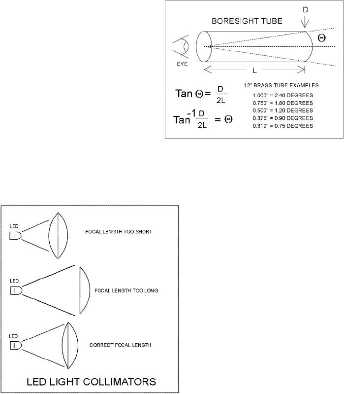
will
only partially use its
available
diameter
and will therefore have a greater
overall
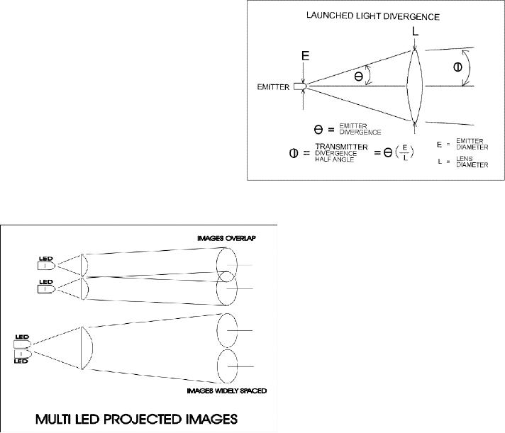
divergence angle. Figure
5e
illustrates
how a lens affects the
launched
divergence
angle from an LED. In
a
similar
way, the size and focal
length of
the
lens used in a light
receiver should be
selected
to insure the light
collected is
focused
properly onto the
detector.
Fortunately,
most light detectors
have
wide
acceptance angles, so you can be
use
them
with a much larger variety
of lens
shapes,
than those required by a
light
emitter.
Figure
5c
Multiple
Lenses, Multiple
Sources
As
illustrated in Figures
5f, there
are two methods that
you can use to collimate
light from multiple
emitters.
If you place a single lens in
front an array of light sources,
multiple images of the
sources
will
be directed toward the
receiver. The
individual
images will be widely
spaced
with
large blank areas between
them. A
single
receiver will detect only one of
the
images.
This method may be useful
if
multiple
receivers need to receive
the
transmitted
light, but it is
not
recommended
if only one receiver is
used.
If
you want to increase the
effective light
intensity
sent to a distant receiver, from
a
transmitter
that uses multiple emitters,
you
will
need multiple lenses.
As
illustrated in Figure
5f an array
of
lenses,
each with its own
light source, will
appear
as one light source, having a
higher
intensity
than a single emitter. This
lens
array
concept is applied in nature by
most
insects
and can be successfully used to
produce
more powerful light sources
that
will
extend the range of a
communications
Figure
5d
system.
Optical
Filters
To
increase the separation distance between
a light transmitter and a receiver,
lenses are often
used.
A
light receiver may use a
lens to collect the weak
light from the transmitter
and focus it onto the
receiver's
detector for processing. But,
the lens will always collect
extra light from the
environment
that
is not wanted. Stray light
will often interfere with
the signals of interest. One
method to reduce
Page
39
of 68
Optical
Through-the-Air Communications Handbook
-David A. Johnson, PE
the
amount of ambient light that
is focused
onto
a detector is to insert an optical
filter
between
the lens and the
detector.
You
may see some optical
filters every
day
without realizing it. As an
example,
the
red clear plastic covers,
used on most
car
taillights, are filters. These
filters block
most
of the unwanted colors
emitted by
the
bulb inside and allow only
the red light
to
pass. These single color band
filters are
called
optical "band pass" filters
and are
the
most valuable type of filter
used in
through-the-air
communications. Other
Figure
5e
filters
also exist. "High pass"
filters are
used
to block light of long
wavelengths
and
pass shorter wavelengths.
Conversely,
"low
pass" filters block short
wavelengths
and
allow long wavelengths to
pass.
Figure
5g shows the
transmission
spectrum
of a low pass filter
material. The
material
has been specifically
designed for
near
infrared use. It is nearly
transparent to
the
near infrared wavelengths but is
very
dark
to most visible light. When
placed in
front
of a silicon detector, the
filter will
block
much of the stray visible
ambient
light,
which may be collected by a
lens.
Figure
5f
But
as you will see in the
section on light
detectors,
such a filter will have a
minimal effect in the
reduction of interference
with
communications
systems that use light
emitting diodes (LEDs) as
light sources. This occurs
because
the
scattered sunlight,
picked
up
by the lens, contains a
sizable amount of infrared
light as well as visible
light. The extra
light,
not
blocked by the filter, will
still be enough to cause
some interference with the
signals from the
LED
source. Even a filter, perfectly
matched to an LEDs spectrum,
would still cause problems.
To
filter
out most of the unwanted
sunlight, a very narrow band
pass filter is needed. But
to take
advantage
of a band pass filters they
must be used with equally
narrow spectrum light
emitters, such
as
semiconductor laser diodes.
One
optical band pass filter,
that can be made to closely
match a laser diode's emission
spectrum, is
an
"interference" filter. Stacking
many very thin layers of
special materials onto a glass
plate makes
interference
filters. By varying the
thickness and the kind of
materials deposited, the width of
the
pass
band and the center wavelength can be
controlled. Figure
5h is an
example of such a
filter.
Page
40
of 68
Optical
Through-the-Air Communications Handbook
-David A. Johnson, PE
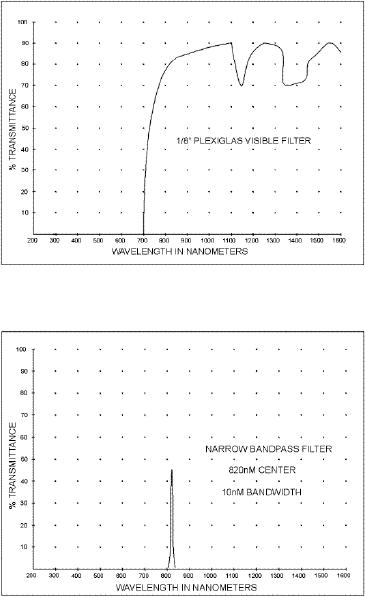
As
can be seen, its bandwidth is
very narrow and happens to
match the emission spectrum
of a
typical
infrared laser diode. If such a
filter were used in a
communications system, almost
all the
laser
light collected would be
allowed to reach the detector,
but it would allow only a
tiny amount
of
stray sunlight to pass.
Narrow band pass filters can
especially be useful when a
single light
receiver
needs to detect light from
only one of many different
modulated laser sources. Different
band
pass filters can be moved in
front of the detector to
reject all sources except
one. Such
techniques
make it possible to have perhaps 10,000
different light receiver
bands without
interference.
Make
Your Own Optical Low
Pass Filter
A
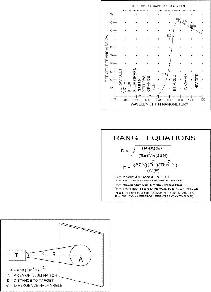
pretty good optical low pass
filter can be
made
using a photographic film
negative.
As
shown in Figure
5h-1, this
filter works
well
at attenuating visible light and
is
pretty
transparent over much of the
near
infrared
wave lengths. However, do
note
that
only light sources with
wave lengths
longer
than 830 nanometers should be
used.
This filter shouldn't be
used for
detecting
light from many lasers,
that
operate
at 780 nanometers. I found
that
Kodak
Kodacolor film with an ASA
of
100
works well. You first
remove the
unexposed
film from the roll and
expose it
to
the light from a cool
white fluorescent Figure
5g
lamp
for about 5 seconds. Then,
you wind
up
the film into roll again and
take it to
your
favorite film developer
for
processing.
Tell them that your not sure
if
the
roll has any images on it
and you can
usually
get them to develop the roll
for
free.
The processed color
negatives form
the
filter material. Keep in mind
that the
film
material is not very robust
and should
not
be used if it can be scratched or
exposed
to moisture.
Inverse
Square Law
One
of the most important
principles you
will
discover in optics is the
inverse square
law.
The law defines how a
light receiver's Figure
5h
ability
to collect light from a
distant emitter will decrease as
the receiver is moved away
from the
source.
To help illustrate the
concept, let's use a water
analogy. Imagine light from
a transmitter as a
fine
spray of water from a small
nozzle that produces a cone shaped
pattern of water droplets.
Also
imagine
our water source to be in the
vacuum of space so that the
spray is not effected by air
or
gravity
and will continue to spread out
evenly, forever. The gallon
per minute rate of water
flowing
through
the nozzle would then
represent the intensity of the
light source. Now, imagine
moving a
bucket
through the spray at various
distances from the nozzle,
the
Page
41
of 68
Optical
Through-the-Air Communications Handbook
-David A. Johnson, PE
bucket
representing a light
receiver's
collection
area. When the bucket is
near
the
nozzle it would fill much
faster than
when
it is positioned farther away.
The
inverse
square law predicts that if
the
distance
between the bucket and the
nozzle
is
doubled, the bucket will fill 4
times
slower.
If it is moved 4 times farther
away
it
will fill 16 times slower. Such
a
reduction
rate
would
continue as the bucket is
moved
away
from the nozzle. Conversely,
if the
bucket
is moved, so it halved the
distance,
it
would fill four times
faster. By knowing
the
flow of water from the
nozzle (light
intensity)
and the spray
pattern
(divergence
angle) you can predict
how
fast
the bucket would be filled
(light
collected)
at any position (range)
within
the
spray. Such a prediction is
described
Figure
5h-1
by
the "optical range equation"
that
combines
the inverse square law
with
some
simple trigonometry.
Range
Equation
The
equation shown in
Figure
5i
combines
the inverse square law
with
some
other known information. You
can
use
the equation to calculate a
number of
factors
for a typical
through-the-air
communications
system. As in
any
algebraic
equation, you can solve for
any
unknown
factor if the other factors
are
known.
As an example, the equation
can
tell
you how large a light
collector you
Figure
5i
will
need at the receiver or the
maximum
distance
you can position the light
receiver
from
the transmitter. Of course,
the
equation
does not take into account
any
other
losses that may exist
within the link,
such
as poor air quality.
Figure
5j
illustrates
how the divergence
angle
effects
the illumination area from a
light
source.
Figure
5j
Page
42
of 68
Optical
Through-the-Air Communications Handbook
-David A. Johnson,
PE
Table of Contents:
- LIGHT THEORY:The Spectrum, Human Eye Response, Silicon Detector Response
- LIGHT DETECTORS:The Silicon PIN Photodiode, Active Area, Response Time
- LIGHT EMITTERS:Light Emitting Diodes (LEDs), Solid State Semiconductor Lasers
- LIGHT SYSTEMS CONFIGURATIONS:Opposed Configuration, Diffuse Reflective Configuration
- LIGHT PROCESSING THEORY:Lenses as Antennas, Light Collimators and Collectors
- OPTICAL RECEIVER CIRCUITS:Current to Voltage Converter Circuits, Post Signal Amplifiers
- OPTICAL TRANSMITTER CIRCUITS:Audio Amplifier with Filters, Pulsed Light Emitters