 |
2
A
Practical Introduction to
Radio
Physics
Wireless
communications make use of
electromagnetic waves to send
sig-
nals
across long distances. From
a user s
perspective,
wireless connections
are
not particularly different
from any other network
connection: your web
browser,
email, and other
applications all work as you
would expect. But
radio
waves have some unexpected
properties compared to Ethernet
cable.
For
example, it s
very
easy to see the path
that an Ethernet cable
takes: lo-
cate
the plug sticking out of
your computer, follow the
cable to the other
end,
and
you ve found
it! You can also be
confident
that running many
Ethernet
cables
alongside each other won
t cause
problems, since the cables
effec-
tively
keep their signals contained
within the wire
itself.
But
how do you know where
the waves emanating from
your wireless card
are
going? What happens when
these waves bounce off of
objects in the
room
or other buildings in an outdoor
link? How can several
wireless cards
be
used in the same area
without interfering with
each other?
In
order to build stable
high-speed wireless links, it is
important to understand
how
radio waves behave in the
real world.
What
is a wave?
We
are all familiar with
vibrations or oscillations in various
forms: a pendu-
lum,
a tree swaying in the wind,
the string of a guitar -
these are all
examples
of
oscillations.
9
10
Chapter
2: A Practical Introduction to Radio
Physics
What
they have in common is that
something, some medium or
object, is
swinging
in a periodic manner, with a
certain number of cycles per
unit of
time.
This kind of wave is
sometimes called a mechanical
wave, since it
is
defined
by the motion of an object or
its propagating
medium.
When
such oscillations travel
(that is, when the
swinging does not
stay
bound
to one place) then we speak
of waves propagating in space.
For ex-
ample,
a singer singing creates
periodic oscillations in his or
her vocal cords.
These
oscillations periodically compress
and decompress the air,
and this
periodic
change of air pressure then
leaves the singers mouth
and travels, at
the
speed of sound. A stone
plunging into a lake causes
a disturbance, which
then
travels across the lake as a
wave.
A
wave has a certain
speed,
frequency, and
wavelength. These
are con-
nected
by a simple relation:
Speed
= Frequency * Wavelength
The
wavelength (sometimes referred to as
lambda, ) is
the distance meas-
ured
from a point on one wave to
the equivalent part of the
next, for example
from
the top of one peak to
the next. The frequency is
the number of whole
waves
that pass a fixed
point in a period of time.
Speed is measured in
meters/second,
frequency is measured in cycles
per second (or Hertz,
ab-
breviated
Hz), and
wavelength is measured in
meters.
For
example, if a wave on water
travels at one meter per
second, and it oscil-
lates
five times
per second, then each
wave will be twenty
centimeters long:
1
meter/second = 5 cycles/second * W
W
= 1 / 5 meters
W
= 0.2 meters = 20 cm
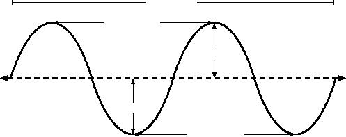
Waves
also have a property called
amplitude. This is
the distance from
the
center
of the wave to the extreme
of one of its peaks, and
can be thought of
as
the "height" of a water
wave. The relationship
between frequency,
wave-
length,
and amplitude are shown in
Figure
2.1.
Waves
in water are easy to
visualize. Simply drop a
stone into the lake
and
you
can see the waves as
they move across the
water over time. In the
case
of
electromagnetic waves, the
part that might be hardest
to understand is:
"What
is it that is oscillating?"
In
order to understand that,
you need to understand
electromagnetic forces.
Chapter
2: A Practical Introduction to Radio
Physics
11
time:
1 second
wavelength
(
)
amplitude
amplitude
wavelength
(
)
Figure
2.1: Wavelength, amplitude,
and frequency. For this
wave, the frequency is
2
cycles
per second, or 2
Hz.
Electromagnetic
forces
Electromagnetic
forces are the forces
between electrical charges
and cur-
rents.
Our most direct access
to those is when our hand
touches a door
handle
after walking on synthetic
carpet, or brushing up against an
electrical
fence.
A more powerful example of
electromagnetic forces is the
lightning we
see
during thunderstorms. The
electrical
force is the
force between
electri-
cal
charges. The magnetic
force is the
force between electrical
currents.
Electrons
are particles that carry a
negative electrical charge.
There are
other
particles too, but electrons
are responsible for most of
what we need to
know
about how radio
behaves.
Let
us look at what is happening in a
piece of straight wire, in
which we push
the
electrons from one and to
the other and back,
periodically. At one
mo-
ment,
the top of the wire is
negatively charged - all the
negative electrons
are
gathered
there. This creates an
electric field
from plus to minus along
the
wire.
The next moment, the
electrons have all been
driven to the other
side,
and
the electric field
points the other way. As
this happens again and
again,
the
electric field
vectors (arrows from plus to
minus) are leaving the
wire, so
to
speak, and are radiated
out into the space
around the wire.
What
we have just described is
known as a dipole (because of
the two poles,
plus
and minus), or more commonly
a dipole
antenna. This is
the simplest
form
of omnidirectional antenna. The
motion of the electric field is
commonly
referred
to as an electromagnetic
wave.
Let
us come back to the
relation:
Speed
= Frequency * Wavelength

12
Chapter
2: A Practical Introduction to Radio
Physics
In
the case of electromagnetic
waves, the speed is
c,
the speed of light.
c
= 300,000 km/s = 300,000,000 m/s =
3*108 m/s
c=f*
E
lectromagnetic
waves differ from mechanical
waves in that they require
no
medium
in which to propagate. Electromagnetic
waves will even
propagate
through
the vacuum of space.
Powers
of ten
In
physics, math, and
engineering, we often express
numbers by powers of
ten.
We will meet these terms
again, e.g. in Giga-Hertz
(GHz), Centi-meters
(cm),
Micro-seconds ( s), and so
on.
Powers
of Ten
10-9
Nano-
1/1000000000
n
10-6
1/1000000
μ
Micro-
Milli-
10-3
1/1000
m
Centi-
10-2
1/100
c
Kilo-
103
1
000
k
Mega-
106
1
000 000
M
Giga-
109
1
000 000 000
G
Knowing
the speed of light, we can
calculate the wavelength for
a given fre-
quency.
Let us take the example of
the frequency of 802.11b
wireless net-
working,
which is
f
= 2.4 GHz
=
2,400,000,000 cycles / second
wavelength
lambda ( )
=
c/f
3*108 /
2.4*109
=
1.25*10-1 m
=
=
12.5
cm
Frequency
and wavelength determine
most of an electromagnetic wave
s be-
havior,
from antennas that we build to
objects that are in the way of
the networks
we
intend to run. They are responsible for many of
the differences between
dif-
Chapter
2: A Practical Introduction to Radio
Physics
13
ferent
standards we might be choosing. Therefore, an
understanding of the basic
ideas
of frequency and wavelength helps a
lot in practical wireless
work.
Polarization
Another
important quality of electromagnetic
waves is polarization.
Polari-
zation
describes the direction of
the electrical field
vector.
If
you imagine a vertically
aligned dipole antenna (the
straight piece of
wire),
electrons
only move up and down,
not sideways (because there
is no room
to
move) and thus electrical
fields
only ever point up or down,
vertically. The
field
leaving the wire and
traveling as a wave has a
strict linear (and in
this
case,
vertical) polarization. If we put
the antenna flat on the
ground, we
would
find horizontal
linear polarization.
direction
of propagation
electric
field
magnetic
field
Figure
2.2: Electric field
and complementary magnetic field
components of an elec-
tromagnetic
wave. Polarization describes
the orientation of the
electric field.
Linear
polarization is just one
special case, and is never quite so
perfect: in gen-
eral,
we will always have some
component of the field pointing other
directions
too.
The most general case is elliptic
polarization, with the
extremes of linear
(only
one direction) and circular polarizations
(both directions at equal strength).
As
one can imagine,
polarization becomes important
when aligning anten-
nas.
If you ignore polarization,
you might have very
little signal even
though
you
have the strongest antennas.
We call this polarization
mismatch.
The
electromagnetic spectrum
Electromagnetic
waves span a wide range of
frequencies (and,
accordingly,
wavelengths).
This range of frequencies
and wavelengths is called
the elec-
tromagnetic
spectrum. The
part of the spectrum most
familiar to humans is
probably
light, the visible portion
of the electromagnetic spectrum.
Light lies
roughly
between the frequencies of
7.5*1014 Hz and 3.8*1014 Hz, correspond-
ing
to wavelengths from circa
400 nm (violet/blue) to 800 nm
(red).
14
Chapter
2: A Practical Introduction to Radio
Physics
We
are also regularly exposed
to other regions of the
electromagnetic spec-
trum,
including Alternating
Current (AC) or grid
electricity at 50/60 Hz,
Ul-
traviolet
(on the higher frequencies
side of visible light),
Infrared (on the
lower
frequencies
side of visible light),
X-Rays / Roentgen radiation,
and many oth-
ers.
Radio
is the
term used for the
portion of the electromagnetic
spectrum
in
which waves can be generated
by applying alternating current to an
an-
tenna.
This is true for the
range from 3 Hz to 300 GHz,
but in the more
nar-
row
sense of the term, the
upper frequency limit would
be 1 GHz.
When
talking about radio, many
people think of FM radio,
which uses a fre-
quency
around 100 MHz. In between
radio and infrared we find the
region of
microwaves
- with frequencies from
about 1 GHz to 300 GHz,
and wave-
lengths
from 30 cm to 1 mm.
The
most popular use of
microwaves might be the
microwave oven, which
in
fact
works in exactly the same
region as the wireless
standards we are
deal-
ing
with. These regions lie
within the bands that
are being kept open
for gen-
eral
unlicensed use. This region
is called the ISM
band, which
stands for
Industrial,
Scientific, and
Medical. Most other parts of
the electromagnetic
spectrum
are tightly controlled by
licensing legislation, with
license values
being
a huge economic factor. This
goes especially for those
parts of the
spectrum
that are suitable for
broadcast (TV, radio) as
well as voice and
data
communication.
In most countries, the ISM
bands have been reserved
for
unlicensed
use.
Approximate
frequency in Hz
104
106
108
1010
1012
1014
1016
1018
1020
1022
1024
microwave
visible
light
X
rays
ultraviolet
radio
gamma
rays
infrared
104
102
100
10-2
10-4
10-6
10-8
10-10
10-12
10-14
10-16
Approximate
wavelength in meters
Figure
2.3: The electromagnetic
spectrum.
The
frequencies most interesting to us
are 2.400 - 2.495 GHz,
which is used
by
the 802.11b and 802.11g
radio standards (corresponding to
wavelengths
of
about 12.5 cm). Other
commonly available equipment
uses the 802.11a
standard,
which operates at 5.150 -
5.850 GHz (corresponding to
wave-
lengths
of about 5 to 6 cm).
Chapter
2: A Practical Introduction to Radio
Physics
15
Bandwidth
A
term you will meet
often in radio physics is
bandwidth. Bandwidth is
sim-
ply
a measure of frequency range. If a
range of 2.40 GHz to 2.48
GHz is
used
by a device, then the
bandwidth would be 0.08 GHz
(or more commonly
stated
as 80MHz).
It
is easy to see that the
bandwidth we define here is
closely related to
the
amount
of data you can transmit
within it - the more room in
frequency
space,
the more data you
can fit in at a
given moment. The term
bandwidth is
often
used for something we should
rather call a data rate, as
in "my Internet
connection
has 1 Mbps of bandwidth",
meaning it can transmit data
at 1
megabit
per second.
Frequencies
and channels
Let
us look a bit closer at how
the 2.4GHz band is used in
802.11b. The
spectrum
is divided into evenly sized
pieces distributed over the
band as in-
dividual
channels. Note
that channels are 22MHz
wide, but are only
sepa-
rated
by 5MHz. This means that
adjacent channels overlap,
and can inter-
fere
with each other. This is
represented visually in Figure
2.4.
1
2
3
4
5
6
7
8
9
10
11
12
13
14
Channel
2.412
2.417
2.422 2.427 2.432 2.437
2.442 2.447 2.452 2.457
2.462 2.467 2.472
2.484
Center
Frequency
(GHz)
22
MHz
Figure
2.4: Channels and center
frequencies for 802.11b.
Note that channels 1,
6,
and
11 do not overlap.
For
a complete list of channels
and their center frequencies
for 802.11b/g
and
802.11a, see Appendix
B.
Behavior
of radio waves
There
are a few simple rules of
thumb that can prove
extremely useful when
making
first
plans for a wireless
network:
·
The longer the wavelength,
the further it goes
·
The longer the wavelength,
the better it travels
through and around
things
·
The shorter the wavelength,
the more data it can
transport
16
Chapter
2: A Practical Introduction to Radio
Physics
All
of these rules, simplified as they
may be, are rather
easy to understand by
example.
Longer
waves travel further
Assuming
equal power levels, waves
with longer wavelengths tend
to travel
further
than waves with shorter
wavelengths. This effect is
often seen in FM
radio,
when comparing the range of
an FM transmitter at 88MHz to the
range
at
108MHz. Lower frequency
transmitters tend to reach
much greater dis-
tances
than high frequency
transmitters at the same
power.
Longer
waves pass around
obstacles
A
wave on water which is 5
meters long will not be
stopped by a 5 mm piece
of
wood sticking out of the
water. If instead the piece
of wood were 50 me-
ters
big (e.g. a ship), it would
be well in the way of the
wave. The distance a
wave
can travel depends on the
relationship between the
wavelength of the
wave
and the size of obstacles in
its path of
propagation.
It
is harder to visualize waves
moving "through" solid
objects, but this is
the
case
with electromagnetic waves.
Longer wavelength (and
therefore lower
frequency)
waves tend to penetrate
objects better than shorter
wavelength
(and
therefore higher frequency)
waves.
For
example, FM radio
(88-
108MHz)
can travel through buildings
and other obstacles easily,
while
shorter
waves (such as GSM phones
operating at 900MHz or
1800MHz)
have
a harder time penetrating
buildings. This effect is
partly due to the
dif-
ference
in power levels used for FM
radio and GSM, but is
also partly due to
the
shorter wavelength of GSM
signals.
Shorter
waves can carry more
data
The
faster the wave swings or
beats, the more information
it can carry -
every
beat or cycle could for
example be used to transport a
digital bit, a '0'
or
a '1', a 'yes' or a 'no'.
There
is another principle that
can be applied to all kinds
of waves, and
which
is extremely useful for
understanding radio wave
propagation. This
principle
is known as the Huygens
Principle, named
after Christiaan Huy-
gens,
Dutch mathematician, physicist
and astronomer 1629 -
1695.
Imagine
you are taking a little
stick and dipping it
vertically into a still
lake's
surface,
causing the water to swing
and dance. Waves will
leave the center
of
the stick - the place
where you dip in - in
circles. Now, wherever water
par-
ticles
are swinging and dancing,
they will cause their
neighbor particles to do
Chapter
2: A Practical Introduction to Radio
Physics
17
the
same: from every point of
disturbance, a new circular
wave will start.
This
is,
in simple form, the Huygens
principle. In the words of
wikipedia.org:
"The
Huygens' principle is a method of
analysis applied to problems
of
wave
propagation in the far field
limit. It recognizes that
each point of an
advancing
wave front is in fact the
center of a fresh disturbance
and the
source
of a new train of waves; and
that the advancing wave as a
whole
may
be regarded as the sum of
all the secondary waves
arising from
points
in the medium already
traversed. This view of wave
propagation
helps
better understand a variety of
wave phenomena, such as
diffrac-
tion."
This
principle holds true for
radio waves as well as waves
on water, for sound
as
well as light - only for
light the wavelength is far
too short for human
be-
ings
to actually see the effects
directly.
This
principle will help us to
understand diffraction as well as
Fresnel zones,
the
need for line of sight as
well as the fact that
sometimes we seem to be
able
to go around corners, with no
line of sight.
Let
us now look into what
happens to electromagnetic waves as
they travel.
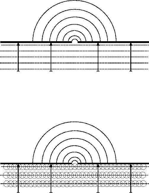
Absorption
When
electromagnetic waves go through
'something' (some material),
they
generally
get weakened or dampened.
How much they lose in
power will de-
pend
on their frequency and of
course the material. Clear
window glass is
obviously
transparent for light, while
the glass used in sunglasses
filter
out
quite
a share of the light
intensity and also the
ultraviolet radiation.
Often,
an absorption coefficient is
used to describe a material s impact
on
radiation.
For microwaves, the two
main absorbent materials
are:
·
Metal.
Electrons can move freely in
metals, and are readily
able to swing
and
thus absorb the energy of a
passing wave.
·
Water.
Microwaves cause water
molecules to jostle around,
thus taking
away
some of the wave s
energy1.
For
the purpose of practical
wireless networking, we may
well consider metal
and
water perfect absorbers: we
will not be able to go
through them (al-
1.
A
commonly held myth is that
water "resonates" at 2.4 GHz,
which is why that frequency
is
used
in microwave ovens. Actually, water
doesn t
appear to
have any particular
"resonant" fre-
quency.
Water spins and jostles
around near radio, and
will heat when in the
presence of high
power
radio waves at just about
any frequency. 2.4 GHz is an
unlicensed ISM frequency, and
so
was
a good political choice for
use in microwave
ovens.
18
Chapter
2: A Practical Introduction to Radio
Physics
though
thin layers of water will
let some power pass).
They are to microwave
what
a brick wall is to light.
When talking about water, we
have to remember
that
it comes in different forms:
rain, fog and mist,
low clouds and so forth
all
will
be in the way of radio
links. They have a strong
influence,
and in many
circumstances
a change in weather can
bring a radio link
down.
There
are other materials that
have a more complex effect
on radio absorp-
tion.
For trees
and
wood,
the amount of absorption
depends on how much
water
they contain. Old dead
dry wood is more or less
transparent, wet
fresh
wood
will absorb a lot.
Plastics
and
similar materials generally do
not absorb a lot of radio
energy-
but
this varies depending on the
frequency and type of
material. Before you
build
a component from plastic
(e.g. weather protection for
a radio device
and
its antennas), it is always a
good idea to measure and
verify that the
ma-
terial
does not absorb radio
energy around 2.4 GHz.
One simple method of
measuring
the absorption of plastic at
2.4 GHz is to put a
sample in a micro-
wave
oven for a couple of
minutes. If the plastic
heats up, then it
absorbs
radio
energy and should not be
used for weatherproofing.
Lastly,
let us talk about ourselves:
humans (as well as other
animals) are
largely
made out of water. As far as
radio networking is concerned, we
may
well
be described as big bags of
water, with the same
strong absorption.
Ori-
enting
an office
access point in such a way
that its signal must
pass through
many
people is a key mistake when
building office networks.
The same goes
for
hotspots, cafe installations,
libraries, and outdoor
installations.
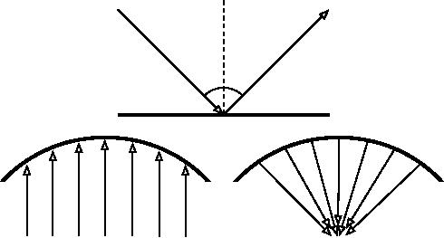
Reflection
Just
like visible light, radio
waves are reflected
when they come in
contact
with
materials that are suited
for that: for radio
waves, the main sources
of
reflection
are metal and water
surfaces. The rules for
reflection
are quite
simple:
the angle at which a wave
hits a surface is the same
angle at which it
gets
deflected.
Note that in the eyes of a
radio wave, a dense grid of
bars
acts
just the same as a solid
surface, as long as the
distance between bars
is
small
compared to the wavelength. At
2.4 GHz, a
one cm metal grid will
act
much
the same as a metal
plate.
Although
the rules of reflection
are quite simple, things
can become very
complicated
when you imagine an office interior
with many many small
metal
objects
of various complicated shapes.
The same goes for
urban situations:
look
around you in city
environment and try to spot
all of the metal
objects.
This
explains why multipath
effects (i.e.
signal reaching their target
along
different
paths, and therefore at
different times) play such
an important role in
wireless
networking. Water surfaces,
with waves and ripples
changing all the
Chapter
2: A Practical Introduction to Radio
Physics
19
time,
effectively make for a very
complicated reflection
object which is more
or
less impossible to calculate
and predict
precisely.
i
r
i=
r
Figure
2.5: Reflection
of radio waves. The angle of
incidence is always equal to
the
angle
of reflection.
A parabolic uses this effect
to concentrate radio waves
spread
out
over its surface in a common
direction.
We
should also add that
polarization has an impact:
waves of different
po-
larization
in general will be reflected
differently.
We
use reflection to
our advantage in antenna
building: e.g. we put huge
pa-
rabolas
behind our radio
transmitter/receiver to collect and
bundle the radio
signal
into a fine
point.
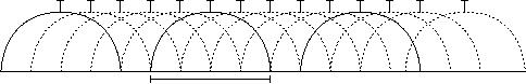
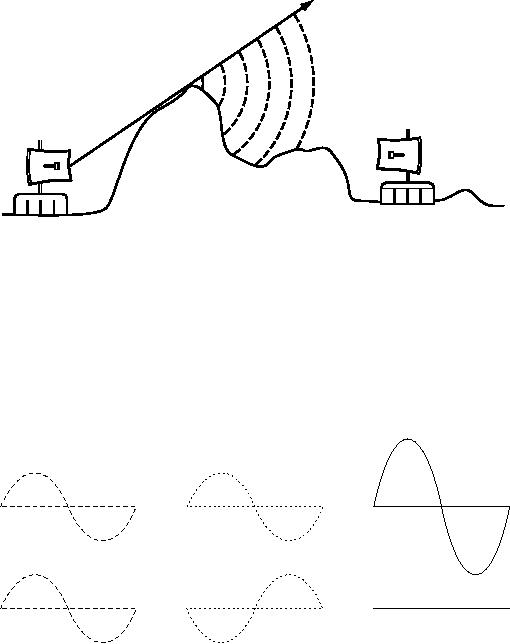
Diffraction
Diffraction
is the apparent bending of
waves when hitting an
object. It is the
effect
of "waves going around
corners".
Imagine
a wave on water traveling in a
straight wave front, just
like a wave
that
we see rolling onto an ocean
beach. Now we put a solid
barrier, say a
wooden
solid fence, in its way to
block it. We cut a narrow
slit opening into
that
wall, like a small door.
From this opening, a
circular wave will start,
and it
will
of course reach points that
are not in a direct line
behind this opening,
but
also
on either side of it. If you
look at this wavefront - and
it might just as well
be
an electromagnetic wave - as a beam (a
straight line), it would be
hard to
explain
how it can reach points
that should be hidden by a
barrier. When
modeled
as a wavefront, the phenomenon
makes sense.
20
Chapter
2: A Practical Introduction to Radio
Physics
Diffraction
Straight
wave front
Figure
2.6: Diffraction through a
narrow slit.
The
Huygens Principle provides
one model for understanding
this behavior.
Imagine
that at any given instant,
every point on a wavefront
can be consid-
ered
the starting point for a
spherical "wavelet". This
idea was later
extended
by
Fresnel, and whether it
adequately describes the
phenomenon is still a
matter
of debate. But for our
purposes, the Huygens model
describes the
effect
quite well.
Diffraction
Potential
spherical wavelets
Figure
2.7: The Huygens
Principle.
Through
means of the effect of
diffraction, waves will
"bend" around corners
or
through an opening in a barrier.
The wavelengths of visible
light are far
too
small
for humans to observe this
effect directly. Microwaves,
with a wave-
length
of several centimeters, will
show the effects of
diffraction when
waves
hit
walls, mountain peaks, and
other obstacles. It seems as if
the obstruction
causes
the wave to change its
direction and go around
corners.
Chapter
2: A Practical Introduction to Radio
Physics
21
Figure
2.8: Diffraction over a
mountain top.
Note
that diffraction comes at
the cost of power: the
energy of the
diffracted
wave
is significantly
less than that of the
wavefront that caused it.
But in
some
very specific
applications, you can take
advantage of the
diffraction
effect
to circumvent obstacles.
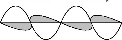
Interference
When
working with waves, one
plus one does not
necessarily equal two.
It
can
also result in zero.
+
=
+
=
Figure
2.9: Constructive and
destructive interference.
This
is easy to understand when
you draw two sine
waves and add up
the
amplitudes.
When peak hits peak,
you will have maximum
results (1 + 1 = 2).
This
is called constructive
interference. When
peak hits valley, you
will
have
complete annihilation ((1 +
(-)1 = 0) - destructive
interference.
You
can actually try this
with waves on water and
two little sticks to
create
circular
waves - you will see
that where two waves
cross, there will be
areas
of
higher wave peaks and
others that remain almost
flat and
calm.
22
Chapter
2: A Practical Introduction to Radio
Physics
In
order for whole trains of
waves to add up or cancel
each other out
per-
fectly,
they would have to have
the exact same wavelength
and a fixed
phase
relation,
this means fixed
positions from the peaks of
the one wave to
the
other's.
In
wireless technology, the
word Interference is typically
used in a wider
sense,
for disturbance through
other RF sources, e.g.
neighboring channels.
So,
when wireless networkers
talk about interference they
typically talk about
all
kinds of disturbance by other
networks, and other sources
of microwave.
Interference
is one of the main sources
of difficulty in
building wireless
links,
especially
in urban environments or closed
spaces (such as a
conference
space)
where many networks may
compete for use of the
spectrum.
Whenever
waves of equal amplitude and
opposite phase cross paths,
the
wave
is annihilated and no signal
can be received. The much
more common
case
is that waves will combine
to form a completely garbled
waveform that
cannot
be effectively used for
communication. The modulation
techniques
and
use of multiple channels
help to deal with the
problem of interference,
but
does not completely
eliminate it.
Line
of sight
The
term line
of sight, often
abbreviated as LOS, is quite
easy to under-
stand
when talking about visible
light: if we can see a point
B from point A
where
we are, we have line of
sight. Simply draw a line
from A to B, and if
nothing
is in the way, we have line
of sight.
Things
get a bit more complicated
when we are dealing with
microwaves.
Remember
that most propagation
characteristics of electromagnetic
waves
scale
with their wavelength. This
is also the case for
the widening of waves
as
they travel. Light has a
wavelength of about 0.5
micrometers, microwaves
as
used in wireless networking
have a wavelength of a few
centimeters.
Consequently,
their beams are a lot
wider - they need more
space, so to
speak.
Note
that visible light beams
widen just the same,
and if you let them
travel
long
enough, you can see
the results despite of their
short wavelength.
When
pointing
a well focussed laser at the
moon, its beam will
widen to well over
100
meters in radius by the time
it reaches the surface. You
can see this
effect
for yourself using an
inexpensive laser pointer
and a pair of
binoculars
on
a clear night. Rather than
pointing at the moon, point
at a distant moun-
tain
or unoccupied structure (such as a
water tower). The
radius of your
beam
will increase as the
distance increases.
Chapter
2: A Practical Introduction to Radio
Physics
23
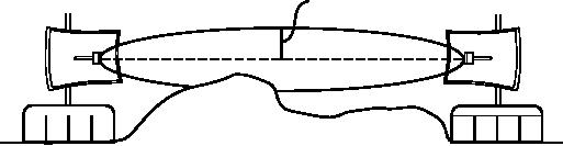
The
line of sight that we need
in order to have an optimal
wireless connection
from
A to B is more than just a
thin line - its shape is
more like that of a
cigar,
an
ellipse. Its width can be
described by the concept of
Fresnel zones.
Understanding
the Fresnel zone
The
exact theory of Fresnel
(pronounced "Fray-nell") zones is
quite compli-
cated.
However, the concept is
quite easy to understand: we
know from the
Huygens
principle that at each point
of a wavefront new circular
waves start,
We
know that microwave beams
widen as they leave the
antenna. We know
that
waves of one frequency can
interfere with each other.
Fresnel zone the-
ory
simply looks at a line from
A to B, and then at the
space around that
line
that
contributes to what is arriving at
point B. Some waves travel
directly from
A
to B, while others travel on
paths off axis.
Consequently, their path
is
longer,
introducing a phase shift
between the direct and
indirect beam.
Whenever
the phase shift is one
full wavelength, you get
constructive inter-
ference:
the signals add up
optimally. Taking this
approach and
calculating
accordingly,
you find there
are ring zones around
the direct line A to B
which
contribute
to the signal arriving at
point B.
Fresnel
radius
Line
of sight
Partial
obstruction
Figure
2.10: The Fresnel zone is
partially blocked on this
link, although the visual
line
of
sight appears
clear.
Note
that there are many
possible Fresnel zones, but
we are chiefly
con-
cerned
with zone 1. If this area
were partially blocked by an
obstruction, e.g.
a
tree or a building, the
signal arriving at the far
end would be
diminished.
When
building wireless links, we
therefore need to be sure
that these zones
be
kept free of obstructions. Of
course, nothing is ever
perfect, so usually in
wireless
networking we check that
about 60 percent of the
radius of the first
Fresnel
zone should be kept
free.
Here
is one formula for
calculating the first
Fresnel zone:
r
= 17.31 * sqrt((d1*d2)/(f*d))
...where
r is
the radius of the zone in
meters, d1
and
d2 are
distances from
the
obstacle to the link end
points in meters, d
is
the total link distance
in
meters,
and f
is
the frequency in MHz. Note
that this gives you
the radius
24
Chapter
2: A Practical Introduction to Radio
Physics
of
the zone, not the
height above ground. To
calculate the height
above
ground,
you need to subtract the
result from a line drawn
directly between
the
tops of the two
towers.
For
example, let s
calculate
the size of the first
Fresnel zone in the middle
of
a
2km link, transmitting at
2.437 GHz (802.11b
channel 6):
r
= 17.31 sqrt((1000 * 1000) / (2437 *
2000))
r
= 17.31 sqrt(1000000 / 4874000)
r
= 7.84 meters
Assuming
both of our towers were
ten meters tall, the
first
Fresnel zone
would
pass just 2.16 meters
above ground level in the
middle of the link.
But
how
tall could a structure at
that point be to clear 60%
of the first
zone?
r
= 0.6 * 17.31 sqrt((1000 * 1000) / (2437 *
2000))
r
= 0.6 * 17.31 sqrt(600000 /
4874000)
r
= 4.70 meters
Subtracting
the result from 10 meters,
we can see that a structure
5.3 meters
tall
at the center of the link
would block up to 40% of the
first
Fresnel zone.
This
is normally acceptable, but to
improve the situation we
would need to
position
our antennas higher up, or
change the direction of the
link to avoid
the
obstacle.
Power
Any
electromagnetic wave carries
energy - we can feel that
when we enjoy
(or
suffer from) the warmth of
the sun. The amount of
energy received in a
certain
amount of time is called
power. The
power P
is
of key importance for
making
wireless links work: you
need a certain minimum power
in order for a
receiver
to make sense of the
signal.
We
will come back to details of
transmission power, losses,
gains and radio
sensitivity
in Chapter
3.
Here we will briefly discuss
how the power P is
de-
fined
and measured.
The
electric field is
measured in V/m (potential
difference per meter),
the
power
contained within it is proportional to
the square of the electric
field
P
~ E2
Practically,
we measure the power by
means of some form of
receiver, e.g.
an
antenna and a voltmeter,
power meter, oscilloscope, or
even a radio card
and
laptop. Looking at the
signal s
power
directly means looking at
the
square
of the signal in
Volts.
Chapter
2: A Practical Introduction to Radio
Physics
25
Calculating
with dB
By
far the most important
technique when calculating
power is calculating
with
decibels
(dB). There is no
new physics hidden in this -
it is just a con-
venient
method which makes
calculations a lot
simpler.
The
decibel is a dimensionless
unit2,
that is, it defines a
relationship between
two
measurements of power. It is defined
by:
dB
= 10 * Log (P1 / P0)
where
P1 and
P0 can
be whatever two values you
want to compare.
Typi-
cally,
in our case, this will be
some amount of power.
Why
are decibels so handy to
use? Many phenomena in
nature happen to
behave
in a way we call exponential.
For example, the human
ear senses a
sound
to be twice as loud as another
one if it has ten times
the physical signal.
Another
example, quite close to our
field of
interest, is absorption.
Suppose
a
wall is in the path of our
wireless link, and each
meter of wall takes
away
half
of the available signal. The
result would be:
0
meters
=
1
(full signal)
1
meter
=
1/2
2
meters
=
1/4
3
meters
=
1/8
4
meters
=
1/16
1/2n = 2-n
n
meters
=
This
is exponential behavior.
But
once we have used the
trick of applying the
logarithm (log), things
be-
come
a lot easier: instead of
taking a value to the n-th
power, we just
multiply
by
n. Instead of multiplying values, we
just add.
Here
are some commonly used
values that are important to
remember:
+3
dB
=
double
power
-3
dB
=
half
the power
+10
dB
=
order
of magnitude (10 times power)
-10
dB
=
one
tenth power
2.
Another
example of a dimensionless unit is
the percent (%) which
can also be used in
all
kinds
of quantities or numbers. While
measurements like feet and
grams are fixed,
dimension-
less
units represent a
relationship.
26
Chapter
2: A Practical Introduction to Radio
Physics
In
addition to dimensionless dB,
there are a number of
relative definitions
that
are based on a certain base
value P0. The most
relevant ones for us
are:
dBm
relative
to P0 = 1 mW
dBi
relative
to an ideal isotropic antenna
An
isotropic
antenna is a
hypothetical antenna that
evenly distributes
power
in
all directions. It is approximated by a
dipole, but a perfect
isotropic an-
tenna
cannot be built in reality.
The isotropic model is
useful for describing
the
relative power gain of a
real world antenna.
Another
common (although less
convenient) convention for
expressing
power
is in milliwatts. Here
are equivalent power levels
expressed in milli-
watts
and dBm:
1
mW
=
0
dBm
2
mW
=
3
dBm
100
mW
=
20
dBm
1
W
=
30
dBm
Physics
in the real world
Don
t worry if
the concepts in this chapter
seem challenging.
Understanding
how
radio waves propagate and
interact with the
environment is a complex
field of
study in itself. Most people
find it
difficult to
understand phenomenon
that
they can t
even
see with their own
eyes. By now you should
understand
that
radio waves don t
travel in a
straight, predictable path. To
make reliable
communication
networks, you will need to
be able to calculate how
much
power
is needed to cross a given
distance, and predict how
the waves will
travel
along the way.
There
is much more to learn about
radio physics than we have
room for here.
For
more information about this
evolving field,
see the resources list in
Ap-
pendix
A.
Table of Contents:
- Where to Begin:Purpose of this book, Fitting wireless into your existing network, Wireless networking protocols
- A Practical Introduction to Radio Physics:What is a wave?, Polarization
- Network Design:Designing the physical network, Mesh networking with OLSR, Estimating capacity
- Antennas & Transmission Lines:Cables, Waveguides, Connectors and adapters, Amplifiers
- Networking Hardware:Wired wireless, Choosing wireless components, Building an access point from a PC
- Security & Monitoring:Physical security, Threats to the network, Authentication
- Solar Power:Solar energy, Photovoltaic system components, The battery
- Building an Outdoor Node:Waterproof enclosures, Providing power, Mounting considerations
- Troubleshooting:Building your team, Proper troubleshooting technique, Common network problems
- Economic Sustainability:Create a Mission Statement, Evaluate the Demand for Potential Offerings
- Case Studies:General advice, Crossing the divide with a simple bridge in Timbuktu, Networking Mérida State
- Appendix A: Resources:Antennas and antenna design, Security
- Appendix B: Channel Allocations
- Appendix C: Path Loss
- Appendix D: Cable Sizes
- Appendix E: Solar Dimensioning:General Data, Component Characteristics
- Glossary