 |

2
Addressing
Modes
2.1.
DATA DECLARATION
The
first instruction of our first
assembly language program was
"mov ax,
5."
Here MOV was the opcode; AX
was the destination operand,
while 5 was
the
source operand. The value of
5 in this case was stored as
part of the
instruction
encoding. In the opcode
B80500, B8 was the opcode
and 0500
was the
operand stored immediately
afterwards. Such an operand is
called
an
immediate operand. It is one of
the many types of operands
available.
Writing
programs using just the
immediate operand type is
difficult. Every
reasonable
program needs some data in
memory apart from
constants.
Constants
cannot be changed, i.e. they
cannot appear as the
destination
operand.
In fact placing them as destination is
meaningless and
illegal
according
to assembly language syntax.
Only registers or data
placed in
memory
can be changed. So real data
is the one stored in memory,
with a
very
few constants. So there must be a
mechanism in assembly language
to
store
and retrieve data from
memory.
To
declare a part of our program as
holding data instead of
instructions we
need a
couple of very basic but
special assembler directives.
The first
directive
is "define byte" written as
"db."
db
somevalue
As a
result a cell in memory will be
reserved containing the
desired value
in it
and it can be used in a
variety of ways. Now we can
add variables
instead
of constants. The other
directive is "define word" or
"dw" with the
same
syntax as "db" but reserving a
whole word of 16 bits
instead of a byte.
There
are directives to declare a
double or a quad word as
well but we will
restrict
ourselves to byte and word
declarations for now. For
single byte we
use db
and for two bytes we use
dw.
To
refer to this variable later
in the program, we need the
address occupied
by this
variable. The assembler is
there to help us. We can
associate a
symbol
with any address that we want to
remember and use that
symbol in
the
rest of the code. The
symbol is there for our own
comprehension of code.
The
assembler will calculate the
address of that symbol using
our origin
directive
and calculating the
instruction lengths or data
declarations in-
between
and replace all references
to the symbol with the
corresponding
address.
This is just like variables
in a higher level language,
where the
compiler
translates them into addresses;
just the process is hidden
from the
programmer
one level further. Such a
symbol associated to a point in
the
program
is called a label and is
written as the label name
followed by a colon.
2.2.
DIRECT ADDRESSING
Now we will
rewrite our first program
such that the numbers 5,
10, and 15
are
stored as memory variables
instead of constants and we
access them
from
there.
Example
2.1
001
; a program to
add three numbers using memory
variables
002
[org
0x0100]
003
mov ax,
[num1]
; load first
number in ax
Computer
Architecture & Assembly Language
Programming
Course
Code: CS401
CS401@vu.edu.pk
004
mov
bx, [num2]
;
load second
number in bx
005
add
ax, bx
;
accumulate
sum in ax
006
mov
bx, [num3]
;
load third number
in bx
007
add
ax, bx
;
accumulate
sum in ax
008
mov
[num4], ax
;
store sum in
num4
009
010
mov
ax,
0x4c00
; terminate
program
011
int
0x21
012
013
num1:
dw
5
014
num2:
dw
10
015
num3:
dw
15
016
num4:
dw
0
Originate
our program at 0100. The
first executable
instruction
002
should
be placed at this
offset.
The
source operand is changed
from constant 5 to [num1].
The
003
bracket
is signaling that the
operand is placed in memory at
address
num1.
The value 5 will be loaded in ax
even though we did
not
specified
it in our program code, rather
the value will be picked
from
memory.
The instruction should be
read as "read the contents
of
memory
location num1 in the ax register."
The label num1 is a
symbol
for us but an address for
the processor while the
conversion
is done
by the assembler.
The
label num1 is defined as a word
and the assembler is
requested
013
to
place 5 in that memory
location. The colon signals
that num1 is a
label
and not an
instruction.
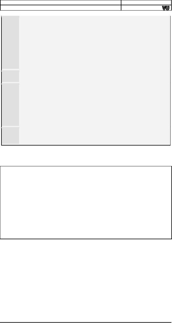
Using
the same process to assemble
as discussed before we examine
the
listing
file generated as a result with
comments removed.
1
2
[org
0x0100]
3
00000000
A1[1700]
mov
ax, [num1]
4
00000003
8B1E[1900]
mov
bx, [num2]
5
00000007
01D8
add
ax, bx
6
00000009
8B1E[1B00]
mov
bx, [num3]
7
0000000D
01D8
add
ax, bx
8
0000000F
A3[1D00]
mov
[num4], ax
9
10
00000012
B8004C
mov
ax,
0x4c00
11
00000015
CD21
int
0x21
12
13
00000017
0500
num1:
dw
5
14
00000019
0A00
num2:
dw
10
15
0000001B
0F00
num3:
dw
15
16
0000001D
0000
num4:
dw
0
The
first instruction of our program
has changed from B80500 to
A11700.
The
opcode B8 is used to move
constants into AX, while the
opcode A1 is
used
when moving data into AX
from memory. The immediate
operand to our
new
instruction is 1700 or as a word
0017 (23 decimal) and
from the bottom
of the
listing file we can observe
that this is the offset of
num1. The
assembler
has calculated the offset of
num1 and used it to replace
references
to num1 in
the whole program. Also
the value 0500 can be
seen at offset
0017 in
the file. We can say
contents of memory location
0017 are 0005 as a
word.
Similarly num2, num3, and num4 are
placed at 0019, 001B,
and
001D
addresses.
When
the program is loaded in the
debugger, it is loaded at offset
0100,
which
displaces all memory
accesses in our program. The
instruction
A11700
is changed to A11701 meaning
that our variable is now placed
at
0117
offset. The instruction is
shown as mov ax, [0117].
Also the data
window
can be used to verify that
offset 0117 contains the
number 0005.
18
Computer
Architecture & Assembly Language
Programming
Course
Code: CS401
CS401@vu.edu.pk
Execute
the program step by step
and examine how the memory
is read and
the
registers are updated, how
the instruction pointer
moves forward, and
how the
result is saved back in
memory. Also observe inside
the debugger
code
window below the code
for termination, that the
debugger is
interpreting
our data as code and showing
it as some meaningless
instructions.
This is because the debugger
sees everything as code in
the
code
window and cannot
differentiate our declared data
from opcodes. It is
our
responsibility that we terminate
execution before our data is
executed as
code.
Also
observe that our naming of num1, num2,
num3, and num4 is no
longer
there inside the debugger.
The debugger is only showing
the numbers
0117,
0119, 011B, and 011D. Our
numerical machine can only
work with
numbers.
We used symbols for our ease
to label or tag certain
positions in
our
program. The assembler
converts these symbols into
the appropriate
numbers
automatically. Also observe
that the effect of "dw" is
to place 5 in
two
bytes as 0005. Had we used
"db" this would have
been stored as 05 in
one
byte.
Given
the fact that the
assembler knows only numbers
we can write the
same
program using a single
label. As we know that num2 is two ahead
of
num1, we
can use num1+2 instead of num2
and let the assembler
calculate
the sum
during assembly
process.
Example
2.2
001
; a program to
add
three numbers
accessed using a single label
002
[org
0x0100]
003
mov
ax, [num1]
;
load first number
in ax
004
mov
bx,
[num1+2]
;
load second
number in bx
005
add
ax, bx
;
accumulate
sum in ax
006
mov
bx,
[num1+4]
;
load third number
in bx
007
add
ax, bx
;
accumulate
sum in ax
008
mov
[num1+6],
ax
;
store sum at
num1+6
009
010
mov
ax,
0x4c00
; terminate
program
011
int
0x21
012
013
num1:
dw
5
014
dw
10
015
dw
15
016
dw
0
The
second number is read from
num1+2. Similarly the
third
004
number
is read from num1+4 and the
result is accessed at
num1+6.
The
labels num2, num3, and num4 are
removed and the data
there
013-016
will be
accessed with reference to num1.
Every
location is accessed with reference to
num1 in this example.
The
expression
"num1+2" comprises of constants
only and can be evaluated
at
the
time of assembly. There are
no variables involved in this
expression. As
we open
the program inside the
debugger we see a verbatim
copy of the
previous
program. There is no difference at
all since the assembler
catered
for
the differences during
assembly. It calculated 0117+2=0119
while in the
previous
it directly knew from the
value of num2 that it has to
write 0119,
but the
end result is a ditto copy
of the previous
execution.
Another
way to declare the above
data and produce exactly
same results is
shown
in the following
example.
Example
2.3
001
; a program to
add three numbers accessed using a single
label
002
[org
0x0100]
003
mov ax,
[num1]
; load first
number in ax
004
mov bx,
[num1+2]
; load second
number in bx
19
Computer
Architecture & Assembly Language
Programming
Course
Code: CS401
CS401@vu.edu.pk
005
add
ax, bx
;
accumulate
sum in ax
006
mov
bx,
[num1+4]
;
load third number
in bx
007
add
ax, bx
;
accumulate
sum in ax
008
mov
[num1+6],
ax
;
store sum at
num1+6
009
010
mov
ax,
0x4c00
; terminate
program
011
int
0x21
012
013
num1:
dw
5, 10, 15,
0
As we do
not need to place labels on
individual variables we can
save
013
space
and declare all data on a
single line separated by
commas.
This
declaration will declare four
words in consecutive
memory
locations
while the address of first
one is num1.
The
method used to access memory
in the above examples is
called direct
addressing.
In direct addressing the
memory address is fixed and
is given in
the
instruction. The actual data
used is placed in memory and
now that data
can be
used as the destination
operand as well. Also the
source and
destination
operands must have the same
size. For example a word
defined
memory
is read in a word sized
register. A last observation is
that the data
0500 in
memory was corrected to 0005
when read in a register. So
registers
contain
data in proper order as a
word.
A last
variation using direct
addressing shows that we can
directly add a
memory
variable and a register
instead of adding a register
into another that
we were
doing till now.
Example
2.4
01
; a program to
add
three numbers
directly in memory
02
[org
0x0100]
03
mov
ax, [num1]
;
load first number
in ax
04
mov
[num1+6],
ax
;
store first number
in result
05
mov
ax,
[num1+2]
;
load second
number in ax
06
add
[num1+6],
ax
;
add
second number to result
07
mov
ax,
[num1+4]
;
load third number
in ax
08
add
[num1+6],
ax
;
add third
number to result
09
10
mov
ax,
0x4c00
; terminate
program
11
int
0x21
12
13
num1:
dw
5, 10, 15,
0
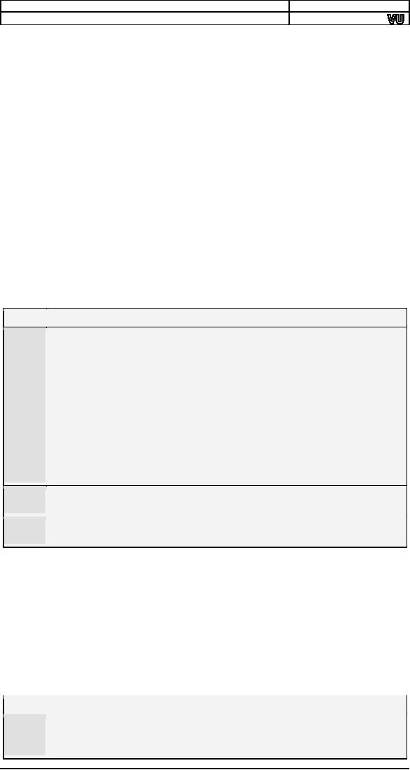
We
generate the following
listing file as a result of
the assembly process
described
previously. Comments are
again removed.
1
2
[org
0x0100]
3
00000000
A1[1900]
mov
ax, [num1]
4
00000003
A3[1F00]
mov
[num1+6],
ax
5
00000006
A1[1B00]
mov
ax,
[num1+2]
6
00000009
0106[1F00]
add
[num1+6],
ax
7
0000000D
A1[1D00]
mov
ax,
[num1+4]
8
00000010
0106[1F00]
add
[num1+6],
ax
9
10
00000014
B8004C
mov
ax,
0x4c00
11
00000017
CD21
int
0x21
12
13
00000019
05000A000F000000
num1:
dw
5, 10, 15,
0
The
opcode of add is changed
because the destination is now a
memory
location
instead of a register. No other
significant change is seen in
the
listing
file. Inside the debugger we
observe that few opcodes
are longer now
and
the location num1 is now translating to
0119 instead of 0117. This
is
done
automatically by the assembler as a
result of using labels
instead of
20
Computer
Architecture & Assembly Language
Programming
Course
Code: CS401
CS401@vu.edu.pk
hard
coding addresses. During
execution we observe that
the word data as it
is read
into a register is read in
correct order. The
significant change in
this
example
is that the destination of
addition is memory. Method to
access
memory
is direct addressing, whether it is
the MOV instruction or the
ADD
instruction.
The
first two instructions of the
last program read a number
into AX and
placed
it at another memory location. A
quick thought reveals that
the
following
might be a possible single
instruction to replace the
couple.
mov
[num1+6],
[num1]
;
ILLEGAL
However
this form is illegal and
not allowed on the Intel
architecture. None
of the
general operations of mov add, sub
etc. allow moving data
from
memory
to memory. Only register to
register, register to memory,
memory to
register,
constant to memory, and
constant to register operations
are
allowed.
The other register to
constant, memory to constant,
and memory to
memory
are all disallowed. Only
string instructions allow
moving data from
memory
to memory and will be discussed in
detail later. As a rule
one
instruction
can have at most one
operand in brackets, otherwise
assembler
will
give an error.
2.3.
SIZE MISMATCH
ERRORS
If we
change the directive in the
last example from DW to DB,
the program
will
still assemble and debug
without errors, however the
results will not be
the
same as expected. When the
first operand is read 0A05
will be read in the
register
which was actually two operands place in
consecutive byte
memory
locations.
The second number will be
read as 000F which is the
zero byte of
num4
appended to the 15 of num3. The
third number will be junk
depending
on the
current state of the
machine. According to our data
declaration the
third
number should be at 0114 but it is
accessed at 011D calculated
with
word
offsets. This is a logical
error of the program. To
keep the declarations
and
their access synchronized is
the responsibility of the
programmer and
not
the assembler. The assembler
allows the programmer to do
everything he
wants
to do, and that can
possibly run on the processor.
The assembler only
keeps
us from writing illegal
instructions which the processor
cannot
execute.
This is the difference
between a syntax error and a
logic error. So
the
assembler and debugger have
both done what we asked them to do
but
the
programmer asked them to do the
wrong chore.
The
programmer is responsible for
accessing the data as word
if it was
declared
as a word and accessing it as a
byte if it was declared as a byte.
The
word
case is shown in lot of
previous examples. If however
the intent is to
treat
it as a byte the following
code shows the appropriate
way.
Example
2.5
001
; a program to
add
three numbers
using byte variables
002
[org
0x0100]
003
mov
al, [num1]
;
load first number
in al
004
mov
bl,
[num1+1]
;
load second
number in bl
005
add
al, bl
;
accumulate
sum in al
006
mov
bl,
[num1+2]
;
load third number
in bl
007
add
al, bl
;
accumulate
sum in al
008
mov
[num1+3],
al
;
store sum at
num1+3
009
010
mov
ax,
0x4c00
; terminate
program
011
int
0x21
012
013
num1:
db
5, 10, 15,
0
The
number is read in AL register which is a
byte register since
the
003
memory
location read is also of
byte size.
The
second number is now placed at num1+1
instead of num1+2
005
because
of byte offsets.
21
Computer
Architecture & Assembly Language
Programming
Course
Code: CS401
CS401@vu.edu.pk
To
declare data db is used
instead of dw so that each
data declared
013
occupies
one byte only.
Inside
the debugger we observe that
the AL register takes
appropriate
values
and the sum is calculated
and stored in num1+3. This
time there is
no
alignment or synchronization error.
The key thing to understand
here is
that
the processor does not
match defines to accesses. It is
the programmer's
responsibility.
In general assembly language
gives a lot of power to
the
programmer
but power comes with responsibility.
Assembly language
programming
is not a difficult task but a
responsible one.
In the
above examples, the
processor knew the size of
the data movement
operation
from the size of the
register involved, for
example in "mov ax,
[num1]"
memory can be accessed as
byte or as word, it has no
hard and fast
size,
but the AX register tells
that this operation has to
be a word operation.
Similarly
in "mov al, [num1]" the AL
register tells that this
operation has to
be a
byte operation. However in
"mov ax, bl" the AX
register tells that
the
operation
has to be a word operation
while BL tells that this
has to be a byte
operation.
The assembler will declare
that this is an illegal
instruction. A 5Kg
bag
cannot fit inside a 1Kg
bag and according to Intel a
1Kg cannot also fit
in
a 5Kg
bag. They must match in
size. The instruction "mov
[num1], [num2]" is
illegal
as previously discussed not
because of data movement
size but
because
memory to memory moves are
not allowed at all.
The
instruction "mov [num1], 5" is
legal but there is no way for
the
processor
to know the data movement
size in this operation. The
variable
num1
can be treated as a byte or as a
word and similarly 5 can be
treated as
a byte
or as a word. Such instructions
are declared ambiguous by
the
assembler.
The assembler has no way to
guess the intent of the
programmer
as it
previously did using the
size of the register
involved but there is no
register
involved this time. And
memory is a linear array and
label is an
address
in it. There is no size
associated with a label. Therefore to
resolve its
ambiguity
we clearly tell our intent to
the assembler in one of the
following
ways.
mov
byte [num1],
5
mov
word [num1],
5
2.4.
REGISTER INDIRECT
ADDRESSING
We have
done very elementary data
access till now. Assume
that the
numbers
we had were 100 and
not just three. This way of
adding them will
cost us
200 instructions. There must be
some method to do a task
repeatedly
on data
placed in consecutive memory
cells. The key to this is
the need for
some
register that can hold
the address of data. So that
we can change the
address
to access some other cell of
memory using the same
instruction. In
direct
addressing mode the memory
cell accessed was fixed
inside the
instruction.
There is another method in which
the address can be placed in
a
register
so that it can be changed.
For the following example we
will take 10
instead
of 100 numbers but the
algorithm is extensible to any
size.
There
are four registers in iAPX88
architecture that can hold
address of
data
and they are BX, BP,
SI, and DI. There are
minute differences in
their
working
which will be discussed later. For
the current example, we will
use
the BX
register and we will take
just three numbers and
extend the concept
with
more numbers in later
examples.
Example
2.6
001
; a program to
add
three numbers
using indirect addressing
002
[org
0x100]
003
mov
bx,
num1
; point bx to first
number
004
mov
ax, [bx]
; load first
number in ax
005
add
bx, 2
; advance bx to
second number
22
Computer
Architecture & Assembly Language
Programming
Course
Code: CS401
CS401@vu.edu.pk
006
add
ax, [bx]
;
add
second number to ax
007
add
bx, 2
;
advance bx to
third number
008
add
ax, [bx]
;
add third
number to ax
009
add
bx, 2
;
advance bx to
result
010
mov
[bx], ax
;
store sum at
num1+6
011
012
mov
ax,
0x4c00
; terminate
program
013
int
0x21
014
015
num1:
dw
5, 10, 15,
0
Observe
that no square brackets
around num1 are used this
time.
003
The
address is loaded in bx and
not the contents. Value of
num1 is
0005
and the address is 0117. So
BX will now contain 0117.
Brackets
are now used around BX. In
iapx88 architecture
brackets
004
can be
used around BX, BP, SI,
and DI only. In iapx386
more
registers
are allowed. The instruction
will be read as "move into
ax
the
contents of the memory
location whose address is in
bx." Now
since
bx contains the address of num1
the contents of num1
are
transferred
to the ax register. Without
square brackets the
meaning
of the
instruction would have been
totally different.
This
instruction is changing the
address. Since we have words
not
005
bytes,
we add two to bx so that it points to
the next word in
memory.
BX now
contains 0119 the address of
the second word in
memory.
This
was the mechanism to change
addresses that we
needed.
Inside
the debugger we observe that
the first instruction is
"mov bx, 011C."
A
constant is moved into BX.
This is because we did not
use the square
brackets
around "num1." The address
of "num1" has moved to 011C
because
the
code size has changed
due to changed instructions. In
the second
instruction
BX points to 011C and the
value read in AX is 0005 which
can be
verified
from the data window.
After the addition BX points
to 011E
containing
000A, our next word, and so
on. This way the BX register
points
to our
words one after another
and we can add them using
the same
instruction
"mov ax, [bx]" without
fixing the address of our
data in the
instructions.
We can also subtract from BX
to point to previous cells.
The
address
to be accessed is now in total program
control.
One
thing that we needed in our
problem to add hundred
numbers was the
capability
to change address. The
second thing we need is a way to
repeat
the
same instruction and a way to know
that the repetition is done
a 100
times,
a terminal condition for the
repetition. For the task we
are introducing
two new
instructions that you should
read and understand as
simple English
language
concepts. For simplicity
only 10 numbers are added in
this
example.
The algorithm is extensible to
any size.
Example
2.7
001
; a program to
add
ten
numbers
002
[org
0x0100]
003
mov
bx,
num1
; point bx to first
number
004
mov
cx, 10
; load count of
numbers in cx
005
mov
ax, 0
; initialize sum
to zero
006
007
l1:
add
ax, [bx]
;
add
number
to ax
008
add
bx, 2
;
advance
bx
to next
number
009
sub
cx, 1
;
numbers
to
be added
reduced
010
jnz
l1
;
if
numbers
remain add
next
011
012
mov
[total], ax
; write back
sum in memory
013
014
mov
ax,
0x4c00
; terminate
program
015
int
0x21
016
017
num1:
dw
10, 20, 30, 40, 50, 10, 20, 30,
40, 50
23
Computer
Architecture & Assembly Language
Programming
Course
Code: CS401
CS401@vu.edu.pk
018
total:
dw
0
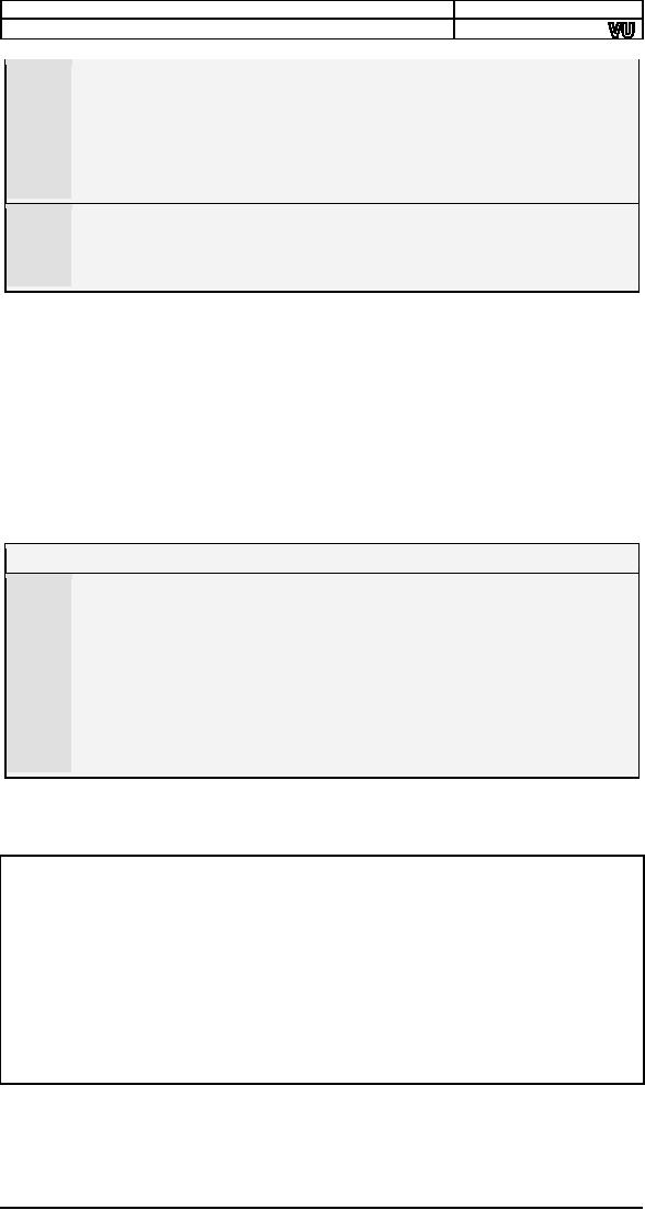
Labels
can be used on code as well.
Just like data labels
they
006
remember
the address at which they
are used. The assembler
does
not
differentiate between
code labels and
data labels.
The
programmer
is responsible for using a
data label as data and a
code
label
as code. The label l1 in
this case is the address of
the following
instruction.
SUB is
the counterpart to ADD with the
same rules as that of
the
009
ADD
instruction.
JNZ
stands for "jump if not
zero." NZ is the condition in
this
010
instruction.
So the instruction is read as "jump to
the location l1 if
the
zero flag is not set." And
revisiting the zero flag
definition "the
zero
flag is set if the last
mathematical or logical operation
has
produced
a zero in its destination."
For example "mov ax, 0" will
not
set
the zero flag as it is not a
mathematical or logical
instruction.
However
subtraction and addition will
set it. Also it is set
even when
the
destination is not a register. Now
consider the
subtraction
immediately
preceding it. If the CX
register becomes zero as a
result
of this
subtraction the zero flag
will be set and the jump will
be
taken.
And jump to l1, the processor
needs to be told each
and
everything
and the destination is an
important part of every
jump.
Just
like when we ask someone to
go, we mention go to this
market
or that
house. The processor is much
more logical than us
and
needs
the destination in every
instruction that asks it to
go
somewhere.
The processor will load l1 in
the IP register and
resume
execution
from there. The processor
will blindly go to the label
we
mention
even if it contains data and
not code.
The CX
register is used as a counter in
this example, BX contains
the
changing
address, while AX accumulates
the result. We have formed a
loop
in
assembly language that
executes until its condition
remains true. Inside
the
debugger we can observe that
the subtract instruction
clears the zero
flag
the
first nine times and
sets it on the tenth time.
While the jump
instruction
moves
execution to address l1 the
first nine times and to
the following line
the
tenth time. The jump
instruction breaks program
flow.
The JNZ
instruction is from the
program control group and is
a conditional
jump,
meaning that if the
condition NZ is true (ZF=0) it will jump
to the
address
mentioned and otherwise it will
progress to the next
instruction. It is
a
selection between two paths. If
the condition is true go
right and otherwise
go
left. Or we can say if the
weather is hot, go this way,
and if it is cold, go
this
way. Conditional jump is the
most important instruction, as it
gives the
processor
decision making capability, so it must be
given a careful
thought.
Some
processors call it branch,
probably a more logical name
for it, however
the
functionality is same. Intel
chose to name it
"jump."
An
important thing in the above
example is that a register is
used to
reference
memory so this form of
access is called register
indirect memory
access.
We used the BX register for
it and the B in BX and BP
stands for
base
therefore we call register
indirect memory access using
BX or BP,
"based
addressing." Similarly when SI or DI is
used we name the
method
"indexed
addressing." They have the
same functionality, with minor
differences
because of which the two are
called base and index.
The
differences
will be explained later, however
for the above example SI or
DI
could
be used as well, but we would
name it indexed addressing
instead of
based
addressing.
24
Computer
Architecture & Assembly Language
Programming
Course
Code: CS401
CS401@vu.edu.pk
2.5.
REGISTER + OFFSET
ADDRESSING
Direct
addressing and indirect
addressing using a single
register are two
basic
forms of memory access.
Another possibility is to use
different
combinations
of direct and indirect
references. In the above
example we used
BX to
access different array
elements which were placed
consecutively in
memory
like an array. We can also
place in BX only the array
index and not
the
exact address and form
the exact address when we
are going to access
the
actual memory. This way the
same register can be used
for accessing
different
arrays and also the
register can be used for
index comparison like
the
following example
does.
Example
2.8
001
; a program to
add
ten numbers using
register + offset addressing
002
[org
0x0100]
003
mov
bx, 0
; initialize array index to
zero
004
mov
cx, 10
; load count of
numbers in cx
005
mov
ax, 0
; initialize sum
to zero
006
007
l1:
add
ax,
[num1+bx]
;
add
number
to ax
008
add
bx, 2
;
advance
bx
to next
index
009
sub
cx, 1
;
numbers
to
be added
reduced
010
jnz
l1
;
if
numbers
remain add
next
011
012
mov
[total], ax
; write back
sum in memory
013
014
mov
ax,
0x4c00
; terminate
program
015
int
0x21
016
017
num1:
dw
10, 20, 30, 40, 50, 10, 20, 30,
40, 50
018
total:
dw
0
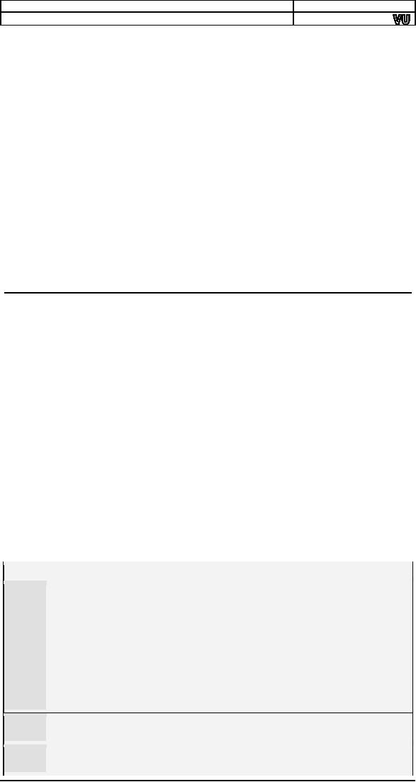
This
time BX is initialized to zero
instead of array base
003
The
format of memory access has
changed. The array base is
added
007
to BX
containing array index at
the time of memory
access.
As the
array is of words, BX jumps in steps of
two, i.e. 0, 2, 4.
008
Higher
level languages do appropriate
incrementing themselves
and
we
always use sequential array
indexes. However in
assembly
language
we always calculate in bytes
and therefore we need to
take
care of
the size of one array
element which in this case is
two.
Inside
the debugger we observe that
the memory access
instruction is
shown
as "mov ax, [011F+bx]" and
the actual memory accessed
is the one
whose
address is the sum of 011F
and the value contained in
the BX
register.
This form of access is of
the register indirect family
and is called
base +
offset or index + offset
depending on whether BX or BP is used or
SI
or DI is
used.
2.6.
SEGMENT ASSOCIATION
All the
addressing mechanisms in iAPX88
return a number called effective
address. For
example in base + offset
addressing, neither the base
nor the
offset
alone tells the desired
cell in memory to be accessed. It is
only after the
addition
is done that the processor
knows which cell to be accessed.
This
number
which came as the result of
addition is called the
effective address.
But the
effective address is just an
offset and is meaningless
without a
segment.
Only after the segment is
known, we can form the
physical address
that is
needed to access a memory
cell.
We
discussed the segmented
memory model of iAPX88 in
reasonable detail
at the
end of previous chapter.
However during the
discussion of addressing
modes
we have not seen the
effect of segments. Segmentation is
there and
it's
all happening relative to a
segment base. We saw DS, CS,
SS, and ES
25

Computer
Architecture & Assembly Language
Programming
Course
Code: CS401
CS401@vu.edu.pk
inside
the debugger. Everything is
relative to its segment
base, even though
we have
not explicitly explained its
functionality. An offset alone is
not
complete
without a segment. As previously
discussed there is a
default
segment
associated to every register which
accesses memory. For
example
CS is
associated to IP by default; rather it is
tied with it. It cannot
access
memory
in any other segment.
In case
of data, there is a bit relaxation
and nothing is tied. Rather
there is
a
default association which can be
overridden. In the case of
register indirect
memory
access, if the register used
is one of SI, DI, or BX the
default
segment
is DS. If however the
register used in BP the
default segment used
is
SS.
The stack segment has a
very critical and fine
use and there is a
reason
why BP is
attached to SS by default. However
these will be discussed in
detail
in the chapter on stack. IP is
tied to CS while SP is tied to
SS. The
association
of these registers cannot be
changed; they are locked
with no
option.
Others are not locked
and can be changed.
To
override the association for
one instruction of one of
the registers BX,
BP, SI
or DI, we use the segment
override prefix. For example
"mov ax,
[cs:bx]"
associates BX with CS for this
one instruction. For the
next
instruction
the default association will
come back to act. The
processor
places
a special byte before the
instruction called a prefix,
just like prefixes
and
suffixes in English language. No
prefix is needed or placed
for default
association.
For example for CS the
byte 2E is placed and for ES
the byte 26
is
placed. Opcode has not
changed, but the prefix byte
has modified the
default
association to association with the
desired segment register for
this
one
instruction.
In all
our examples, we never declared a
segment or used it explicitly,
but
everything
seemed to work fine. The
important thing to note is
that CS, DS,
SS,
and ES all had the
same value. The value
itself is not important but
the
fact
that all had the
same value is important. All
four segment windows
exactly
overlap. Whatever segment
register we use the same
physical memory
will be
accessed. That is why everything was
working without the mention
of
a
single segment register.
This is the formation of COM
files in IBM PC. A
single
segment contains code, data,
and the stack. This
format is operating
system
dependant, in our case defined by
DOS. And our operating
system
defines
the format of COM files such
that all segments have
the same value.
Thus
the only meaningful thing
that remains is the
offset.
For
example if BX=0100, SI=0200,
and CS=1000 and the
memory access
under
consideration is [cs:bx+si+0x0700], the
effective address formed
is
bx+si+0700
= 0100 + 0200 + 0700 = 0A00.
Now multiplying the
segment
value
by 16 makes it 10000 and
adding the effective address
00A00 forms
the
physical address
10A00.
2.7.
ADDRESS WRAPAROUND
There
are two types of wraparounds.
One is within a single segment
and
the
other is inside the whole
physical memory. Segment
wraparound occurs
when
during the effective address
calculation a carry is generated.
This carry
is
dropped giving the effect
that when we try to access beyond
the segment
limit,
we are actually wrapped
around to the first cell in
the segment. For
example
if BX=9100, DS=1500 and the
access is [bx+0x7000] we form
the
effective
address 9100 + 7000 = 10100.
The carry generated is
dropped
forming
the actual effective address
of 0100. Just like a circle
when we
reached
the end we started again
from the beginning. An arc
at 370 degrees
is the
same as an arc at 10 degrees. We
tried to cross the segment
boundary
and it
pushed us back to the start.
This is called segment
wraparound. The
physical
address in the above example
will be 15100.
The
same can also happen at
the time of physical address
calculation. For
example
BX=0100, DS=FFF0 and the
access under consideration
is
[bx+0x0100].
The effective address will be
0200 and the physical
address will
26

Computer
Architecture & Assembly Language
Programming
Course
Code: CS401
CS401@vu.edu.pk
be
100100. This is a 21bit
answer and cannot be sent on
the address bus
which is 20
bits wide. The carry is
dropped and just like
the segment
wraparound
our physical memory has
wrapped around at its very
top. When
we
tried to access beyond
limits the actual access is
made at the very
start.
This
second wraparound is a bit different in
newer processor with
more
address
lines but that will be explained in
later chapters.
2.8.
ADDRESSING MODES
SUMMARY
The
iAPX88 processor supports
seven modes of memory
access. Remember
that
immediate is not an addressing
mode but an operand type.
Operands
can be
immediate, register, or memory. If
the operand is memory one of
the
seven
addressing modes will be used to
access it. The memory
access
mechanisms
can also be written in the
general form "base + index +
offset"
and we
can define the possible
addressing modes by saying
that any one,
two, or
none can be skipped from
the general form to form a
legal memory
access.
There
are a few common mistakes
done in forming a valid
memory access.
Part of
a register cannot be used to
access memory. Like BX is
allowed to
hold an
address but BL or BH are not.
Address is 16bit and must
be
contained
in a 16bit register. BX-SI is not
possible. The only thing
that we
can do
is addition of a base register with an
index register. Any
other
operation
is disallowed. BS+BP and
SI+DI are both disallowed as
we cannot
have
two base or two index registers in
one memory access. One
has to be a
base
register and the other
has to be an index register
and that is the
reason
of
naming them differently.
Direct
A fixed
offset is given in brackets
and the memory at that
offset is
accessed.
For example "mov [1234],
ax" stores the contents of
the AX
registers
in two bytes starting at address
1234 in the current data
segment.
The
instruction "mov [1234], al"
stores the contents of the
AL register in the
byte at
offset 1234.
Based Register
Indirect
A base
register is used in brackets
and the actual address
accessed
depends
on the value contained in
that register. For example
"mov [bx], ax"
moves
the two byte contents of the
AX register to the address
contained in
the BX
register in the current data
segment. The instruction
"mov [bp], al"
moves
the one byte content of
the AL register to the
address contained in
the
BP
register in the current
stack segment.
Indexed Register
Indirect
An
index register is used in
brackets and the actual
address accessed
depends
on the value contained in
that register. For example
"mov [si], ax"
moves
the contents of the AX
register to the word
starting at address
contained
in SI in the current data
segment. The instruction
"mov [di], ax"
moves
the word contained in AX to
the offset stored in DI in
the current data
segment.
Based Register
Indirect + Offset
A base
register is used with a constant
offset in this addressing
mode. The
value
contained in the base
register is added with the
constant offset to
get
the
effective address. For
example "mov [bx+300], ax"
stores the word
contained
in AX at the offset attained by
adding 300 to BX in the
current
data
segment. The instruction
"mov [bp+300], ax" stores
the word in AX to
the
offset attained by adding
300 to BP in the current
stack segment.
27
Computer
Architecture & Assembly Language
Programming
Course
Code: CS401
CS401@vu.edu.pk
Indexed Register Indirect +
Offset
An
index register is used with a
constant offset in this
addressing mode.
The
value contained in the index
register is added with the
constant offset to
get
the effective address. For
example "mov [si+300], ax"
moves the word
contained
in AX to the offset attained by
adding 300 to SI in the
current data
segment
and the instruction "mov
[di+300], al" moves the
byte contained in
AL to
the offset attained by
adding 300 to DI in the
current data segment.
Base +
Index
One
base and one index
register is used in this
addressing mode. The
value
of the base register and
the index register are
added together to get
the
effective
address. For example "mov
[bx+si], ax" moves the
word contained in
the AX
register to offset attained by
adding BX and SI in the
current data
segment.
The instruction "mov
[bp+di], al" moves the
byte contained in AL to
the
offset attained by adding BP
and DI in the current stack
segment.
Observe
that the default segment is
based on the base register
and not on
the
index register. This is why
base registers and index
registers are named
separately.
Other examples are "mov
[bx+di], ax" and "mov
[bp+si], ax." This
method
can be used to access a two
dimensional array such that
one
dimension
is in a base register and
the other is in an index
register.
Base + Index +
Offset
This is
the most complex addressing
method and is relatively
infrequently
used. A
base register, an index
register, and a constant
offset are all used
in
this
addressing mode. The values
of the base register, the
index register, and
the
constant offset are all
added together to get the
effective address.
For
example
"mov [bx+si+300], ax" moves
the word contents of the AX
register to
the
word in memory starting at
offset attained by adding BX,
SI, and 300 in
the
current data segment.
Default segment association is
again based on the
base
register. It might be used with
the array base of a two
dimensional array
as the
constant offset, one
dimension in the base
register and the other
in
the
index register. This way all
calculation of location of the
desired element
has
been delegated to the
processor.
EXERCISES
1.
What is
a label and how does the
assembler differentiates
between
code
labels and data
labels?
2.
List
the seven addressing modes
available in the 8088
architecture.
3.
Differentiate
between effective address
and physical address.
4.
What is
the effective address
generated by the
following
instructions?
Every instruction is independent of
others. Initially
BX=0x0100,
num1=0x1001, [num1]=0x0000, and
SI=0x0100
a. mov
ax, [bx+12]
b. mov
ax, [bx+num1]
c. mov
ax, [num1+bx]
d. mov
ax, [bx+si]
5.
What is
the effective address
generated by the
following
combinations
if they are valid. If not
give reason.
Initially
BX=0x0100,
SI=0x0010, DI=0x0001, BP=0x0200,
and SP=0xFFFF
a.
bx-si
b.
bx-bp
c.
bx+10
d.
bx-10
e.
bx+sp
f.
bx+di
6.
Identify
the problems in the
following instructions and
correct them
by
replacing them with one or two
instruction having the
same
effect.
28

Computer
Architecture & Assembly Language
Programming
Course
Code: CS401
CS401@vu.edu.pk
a.
mov
[02], [
22]
b.
mov
[wordvar],
20
c. mov
bx,
al
d. mov
ax,
[si+di+100]
7.
What is the function
of segment override prefix and
what
changes
it brings to the opcode?
8.
What are the two
types of address wraparound? What
physical
address is accessed with [BX+SI] if
FFFF is loaded in
BX, SI, and
DS.
9.
Write
instructions to do the following.
a. Copy
contents of memory location with
offset 0025 in the
current
data segment into AX.
b. Copy
AX into memory location with
offset 0FFF in the
current
data segment.
c. Move
contents of memory location with
offset 0010 to
memory
location with offset 002F in
the current data
segment.
10.
Write a program to calculate the square
of 20 by using a loop
that adds 20 to the
accumulator 20 times.
29
Table of Contents:
- Introduction to Assembly Language Programming
- Addressing Modes: Data Declaration, Direct, Register Indirect , Offset Addressing
- Branching: Comparison and Conditions, Conditional ,Unconditional Jump
- Manipulations: Multiplication Algorithm, Shifting and Rotations, Bitwise Logical Operations
- Subroutines: Program Flow, Stack, Saving and Restoring Registers
- Display Memory: ASCII Codes, Display Memory Formation, Assembly Language
- String Instructions: String Processing, Clearing Screen, String Printing, Length
- Software Interrupts: Hooking an Interrupt, BIOS and DOS Interrupts
- Real Time Interrupts and Hardware Interfacing
- Debug Interrupts: Debugger using single step interrupt, breakpoint interrupt
- Multitasking: Concept, Elaborate, Multitasking Kernel as TSR
- Video Services: BIOS Video Services, DOS Video Services
- Secondary Storage: Storage Access Using BIOS, DOS, Device Drivers
- Serial Port Programming: Serial Communication
- Protected Mode Programming: VESA Linear Frame Buffer, Interrupt Handling
- Interfacing with High Level Languages: Calling Conventions, Calling C from Assembly
- Comparison: Motorolla 68K Processors, Sun SPARC Processor