 |
CS302 -
Digital Logic & Design
Lesson
No. 37
REDUCED
NUMBER OF INPUT
LATCHES
The
number of latches used to
store the external inputs
can be reduced to two if
the
REQ1,
FLOOR1 and OPEN button
outputs (pressed when
elevator is on the first
floor) are
stored on
one latch and the
REQ2, FLOOR2 and OPEN
button outputs pressed when
elevator
is on the
second floor) are stored on
the second latch. This
also simplifies the
Boolean
expressions
required to generate the
excitation inputs for the
next states. The next
state table
for
REQ1, FLOOR1 and OPEN
inputs indicates that the
REQ1 can be pressed at any
time
either on
the first floor or the
second floor. The FLOOR1
request can also be pressed
at any
time,
however if the elevator is
already on the first floor
then requests for FLOOR1
can be
discarded.
Similarly, if OPEN button is
pressed when the elevator is
on the first floor is
considered as a
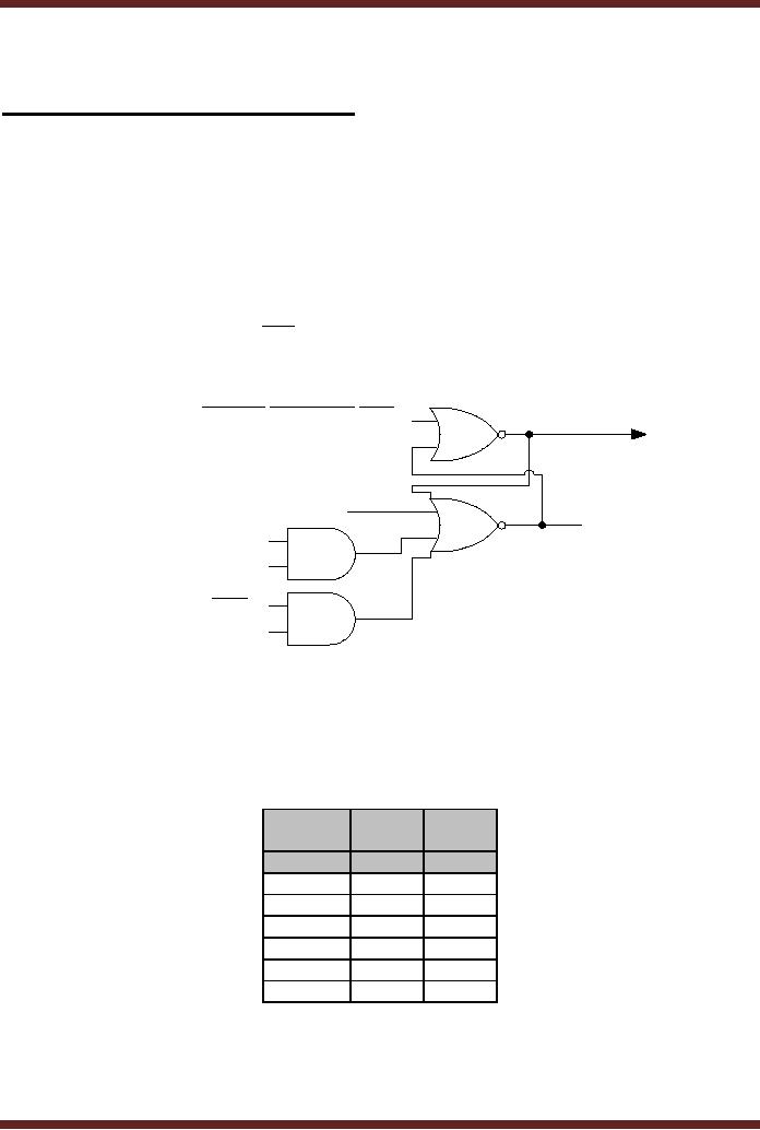
valid request. The Boolean
expressions that set the
latch SR1 is
REQ1 + FLOOR1.DIR + OPEN.DIR
. The
circuit diagram of the SR1
latch is shown.
Figure
37.1.
Re
set
Q
DOOR.MOTION.DIR
REQ1
DIR
FLOOR1
Set
DIR
OPEN
Figure
37.1 SR1 latch which
stores the status of the
REQ1, FLOOR1 and OPEN
buttons
The
DIR variable indicates the
current floor. IF DIR=0, the
elevator is on the first
floor and if
DIR=1,
the elevator is on the
second floor. Similarly, the
OPEN input sets the
SR1 latch when
it is pressed
when the elevator is on the
first floor. The simplified
next state table for
inputs
REQ1,
FLOOR1 and OPEN in terms of
SR1 latch is shown. Table
37.1.
Present
Next
Next
State
State
State
SR1=0
SR1=1
W1(000)
x
x
C1(100)
C1
W1
UP(110)
x
x
W2(001)
C2
DO
C2(101)
C2
DO
DO(111)
x
x
Table
37.1
Simplified
State table for Elevator
Control for REQ1, FLOOR1
and OPEN inputs
377
CS302 -
Digital Logic & Design
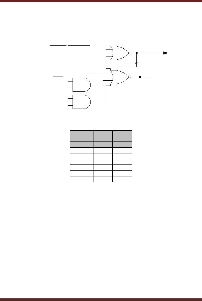
The
state of inputs REQ2, FLOOR2
and OPEN can similarly be
represented by
setting/resetting
the second latch SR2.
The circuit diagram and
the Boolean expression
can
similarly be
represented. Figure 37.2 and
Table 37.2.
Re
set
Q
DOOR.MOTION.DIR
REQ2
DIR
FLOOR2
Set
DIR
OPEN
Figure
37.2 SR2 latch which
stores the status of the
REQ2, FLOOR2 and OPEN
buttons
Present
Next
Next
State
State
State
SR2=0
SR2=1
W1(000)
C1
UP
C1(100)
C1
UP
UP(110)
x
x
W2(001)
x
x
C2(101)
C2
W2
DO(111)
x
x
Table
37.2
Simplified
State table for Elevator
Control for REQ2, FLOOR2
and OPEN inputs
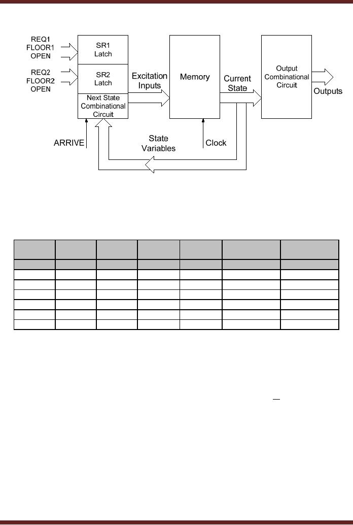
The
modified Block diagram of
the Elevator State Machine
which uses the two
SR1,
SR2
latches instead of the
previously discussed five
latches is shown. Figure
37.3. The Next
State
Combinational Circuit block is
replaced by latches SR1 and
SR2 which handle
the
REQ1,
FLOOR1, REQ2, FLOOR2 and
OPEN external inputs. The
external input ARRIVE
is
connected to
the Next State Combinational
circuit along with the
Present State inputs
which
determine
the excitation inputs for
the memory element.
378
CS302 -
Digital Logic & Design
Figure
37.3 Modified Block diagram
of the Elevator State
Machine
The
Next State Table for
the Elevator State Machine
based on the inputs SR1,
SR2
and
ARRIVAL is shown. Table
37.3. The Next State
table is implemented using
the two
simplified
state tables, table 37.1
and table 37.2 and
the ARRIVE input.
Present
Next
Next
Next
Next
Next
State
Next
State
State
State
State
State
State
SR1=0
SR1=1
SR2=0
SR2=1
ARRIVAL=0
ARRIVAL=1
W1(000)
x
x
C1(100)
UP(110)
x
x
C1(100)
C1(100)
W1(000)
C1(100)
UP(110)
x
x
UP(110)
x
x
x
x
UP(110)
W2(001)
W2(001)
C2(101)
DO(111)
x
x
x
x
C2(101)
C2(101)
DO(111)
C2(101)
W2(001)
x
x
DO(111)
x
x
x
x
DO(111)
W1(000)
Table
37.3
The
Next State Table based on
SR1, SR2 and ARRIVAL
inputs
The
ABEL Input file for
Elevator State
Machine
The
main declaration and
definition sections of the
ABEL input file for
the Elevator
State
Machine are described. Table
36.4.
The
SR1, SR1_, SR2, SR2_
variables are the S-R
latch Q and Q outputs for
latches
SR1
and SR2. These latches
are implemented using the
AND-OR gates of the PLD
device,
there
outputs are available at the
output pins 16, 17, 18
and 19 of the GAL16V8
device. These
outputs
are generated by combinational
circuits therefore these
outputs are defined
as
ISTYPE
`com.buffer'. These outputs
are feed back to the AND
gate array for connection to
the
D flip-flops.
The outputs from the
three D flip-flops, DOOR,
MOTION and DIR are
declared as
ISTYPE
`reg.buffer' as these three
outputs are the outputs of
the sequential circuit D
flip-flops
in the
OLMC modules. Table
36.4a.
379

CS302 -
Digital Logic & Design
Pin
Declaration
CLK,
!OLE
Pin
1,11;
REQ1,
REQ2
Pin
2,3;
FLOOR1,
FLOOR2, OPEN, ARRIVE
Pin
4, 5, 6,
7;
SR1,
SR1_
Pin
16, 17
ISTYPE `com.buffer';
SR2,
SR2_
Pin
18, 19
ISTYPE `com.buffer';
DOOR,
MOTION, DIR
Pin
12,
13, 14 ISTYPE
`reg.buffer';
Table
36.4a
Pin
Declarations of the Elevator
Input and Output
signals
The
operation of the Sequential
state machine in the ABEL
file is defined in the form
of
a State
diagram instead of Boolean
expressions. Before defining
the State Diagram, all
the
states
are defined. The six
states can be defined using
the statement WAIT1 =
[0,0,0],
CLOSE1 =
[1,0,0] etc. The alternate
method for defining the
states is by prefixing the
binary
number
with ^B. Table 37.4b.
State
Definition
CONSTATE =
[DOOR, MOTION, DIR];
WAIT1
=
^B000;
CLOSE1
=
^B100;
UP
=
^B110;
WAIT2 =
^B001;
CLOSE2
=
^B101;
DOWN =
^B111;
Table
37.4b
State
Definition of the Elevator
Controller
The
statements defining the
State diagram for the
Elevator State Machine are
derived from the
State
Table. Table 37.3. The
State Diagram definition is
defined in Table
37.4c.
State
Diagram
State_diagram
CONSTATE
State
WAIT1:
if (SR2)
then UP else CLOSE1;
State
CLOSE1:
if (SR2)
then UP else if SR1 then
WAIT1 else CLOSE1;
State
UP:
if (ARRIVE)
then WAIT2 else
UP;
State
WAIT2:
if (SR1)
then DOWN else
CLOSE2;
State
CLOSE2:
if (SR1)
then DOWN else if SR2
then WAIT2 else
CLOSE2;
State
DOWN:
if (ARRIVE)
then WAIT1 else
DOWN;
Table
37.4c
State
diagram for the Elevator
Controller
The
equations defining the Set
and Reset input for
the two latches SR1
and SR2 are
defined
in the
Equation Definition part of
the ABEL input file.
The CONSTATE.CLK = Clock is
used to
indicate
that the CONSTATE state
variables change on a clock
transition. Table 37.4d.
The
`FB'
indicates that the DOOR,
MOTION and DIR output
signals are feed back to
the AND gate
array.
380

CS302 -
Digital Logic & Design
Equation
Definition
CONSTATE.CLK =
Clock;
SR1 =
REQ1 # !DIR.FB & OPEN #
DIR.FB & FLOOR1 #
!SR1_;
SR1_ =
(!DOOR.FB & !MOTION.FB & !DIR.FB)
# !SR1;
SR2 =
REQ2 # !DIR.FB & OPEN #
DIR.FB & FLOOR2 #
!SR2_;
SR2_ =
(!DOOR.FB & !MOTION.FB & DIR.FB)
# !SR2;
Table
37.4d
Equations
for the latches SR1
and SR2
A separate
GAL16V8 is used to implement
the 7-Segment floor display
and the Up and
Down
direction arrows. The floor
display circuit is a combinational
circuit which uses
the
MOTION
and DIR inputs two
determine the floor number
and the direction of the
display
arrow.
Design
Example: Traffic Signal
Control System
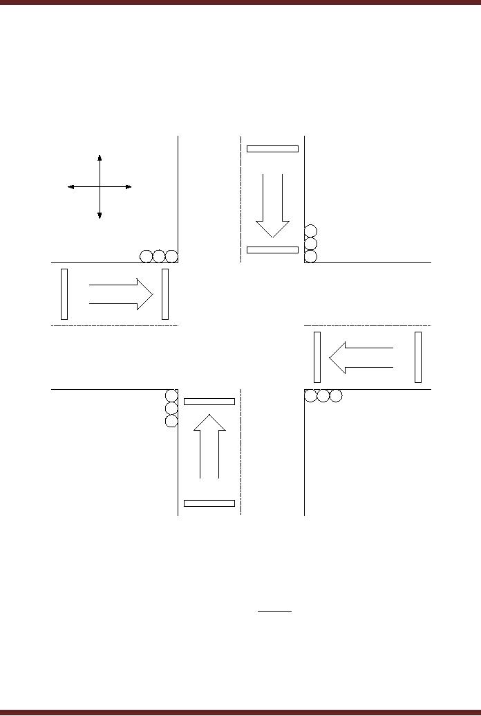
A road
intersection is shown on the
diagram. Figure 37.4. On
each section of the
road
two
sensors determine the
presence and arrival of
vehicles. Sensor 1 is activated if a
car is
waiting
and Sensor 2 is activated
when an arriving vehicle
passes over the sensor.
The
sensors
installed on the North and
South section of the road
are connected together
and
determine
the presence of vehicle(s) on
the North-South section of
the road. The
sensors
installed on
the East and West
section of the road are
connected together and
determine the
presence of
vehicle(s) on the East-West
section of the Road. During
the day when traffic
flow
is heavy at
the intersection, the
traffic light is cycled
every 5 minutes. That is,
the traffic signal
controlling
the North-South section is
Green for 5 minutes and
then Red for 5
minutes,
Similarly,
the traffic signal
controlling the East-west
section is Red for 5 minutes
and Green for
the
next 5 minutes. During the
night when traffic is
relatively light it stops a
car for a maximum
time of 1
minute, unless a car
approaches the intersection on
the cross road in which
case the
traffic
signal turns red and
stops the approaching car
and allows the waiting
car to proceed.
For
example, a car is waiting at
South approach of the
intersection. A car approaching
the
intersection on
the cross road from
the East direction is
stopped and the waiting
car on the
South
section is allowed to proceed.
The approaching car is
detected by Sensor 2 installed
on
the
East road section. If no
other cars are arriving at
the intersection the waiting
car on the
East
approach is allowed to proceed
after 1 minute.
Traffic
Signal Controller Inputs and
Outputs
The
State Machine which controls
the Traffic Signal has
several inputs and
outputs.
The
inputs are the
· NSSR:
The NSSR is activated when a
car is over either of the
four sensors on the
North-
South
section of the road
· EWSR:
The EWSR is activated when a
car is over either of the
four sensors on the
East-
West
section of the road
A Timer is
used to count the 5 minute
and 1 minute traffic signal
cycle during the day
and
night.
Two signals LTIME and
STIME provide the timing
inputs to the State
Machine.
· LTIME:
The
LTIME signal is activated if 5
minutes have elapsed; the
signal remains
active
unless the timer is
reset.
· STIME:
The
STIME signal is activated if 1
minute has elapsed; the
signal remains
active
unless the timer is
reset.
The
outputs of the State Machine
are
· NSGrn:
The
Green signal controlling the
traffic on the North-South
section
· NSYel:
The
Yellow signal controlling
the traffic on the
North-South section
381
CS302 -
Digital Logic & Design
·
NSRed:
The Red signal
controlling the traffic on
the North-South
section
·
EWGrn:
The Green signal
controlling the traffic on
the East-West section
·
EWYel:
The
Yellow signal controlling
the traffic on the East-West
section
·
EWRed:
The Red signal
controlling the traffic on
the East-West section
·
TMRST:
The Reset signal which
resets the timer after
the LTIME or the STIME
signals
are
activated to indicate a time
interval of 5 and 1 minutes
respectively.
North
West
East
South
G
Y
G Y R
R
Sensor
1
R
RYG
Traffic
Signal
Y
G
Sensor
2
Figure
37.4 The Traffic
signals and sensors at a
Traffic Intersection
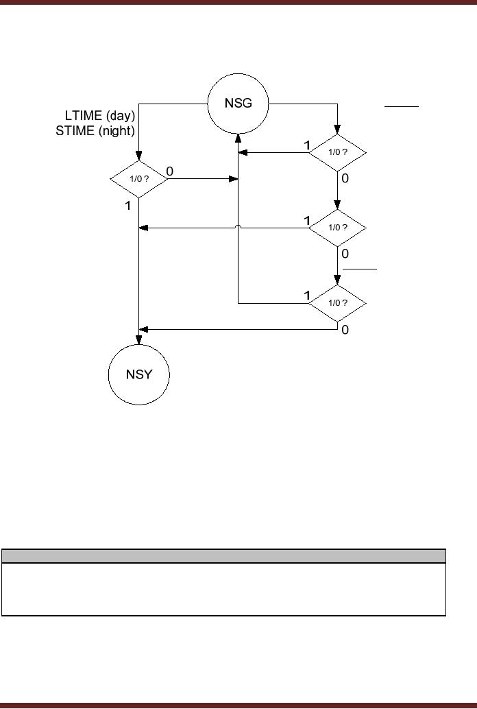
Assuming
that the initial state is
the NSG (North-South Green)
State, during the day
time the
LTIME
timer output is available as an
input signal to the State
Machine. As long as LTIME
is
inactive
the State Machine remains in
its current state NSG,
otherwise it switches to the
next
state NSY
(North-South Yellow). During
the night time the
STIME timer output is
available as
an input
signal to the State machine.
If the STIME is inactive the
State Machine remains in
its
current
state NSG, otherwise it
switches to the NSY state. If a
car arrives at the
East-West
cross
road it is made to stop,
that is when EWSR.NSSR , the state NSG
remains unchanged.
If cars
arrive on both the NS and EW
sections, both the cars
have to be stopped and the
state
changes to
NSY. If a car arrives at the
NS section it has to be stopped
therefore the state
changes to
NSY. The information is
represented by a flowchart. Figure
37.5
382
CS302 -
Digital Logic & Design
The
State Machine can be
implemented using a GAL16V8
device. The declaration
and
definition
parts of the ABEL input
file for the Traffic
Light Controller are
described in tables.
Table
37.5
EWSR.NSSR
EWSR.NSSR
NSSR
Figure
37.5
Flow
chart of conditions which
switch the state from NSG to
NSY
The
pin declaration defines the
pins for the CLOCK,
NSSR, EWSR, LTIME and
STIME
inputs to
the Traffic Light Controller
and the pins for
the Q0, Q1, Q2 State
variable outputs and
the
Timer reset TMRST outputs.
The state variable outputs
are available from the D
flip-flops
of the
OLMC modules and are
available in the inverted
form, therefore they are
defined of type
`reg.invert'.
The TMRST signal is an
active low signal which
resets the counter when
the
Controller
switches to certain states.
The TMRST is an active low
signal and is based on
a
combinational
circuit therefore its is
defined of type `com.invert'.
Table 37.5a
Pin
Declaration
CLOCK,
!OLE
pin 1,
11;
NSSR,
EWSR, LTIME, STIME
pin 2, 3, 8,
9;
Q0,
Q1, Q2
pin
17, 16, 15 ISTYPE
`reg.invert';
TMRST
pin 14
ISTYPE `com.invert';
Table
37.5a
Pin
Declarations for the Input
and Output pins to the
Controller circuit
383
CS302 -
Digital Logic & Design
Definitions
TRSTATE =
[Q2, Q1, Q0];
NSG
= [ 0 , 0,
0];
NSY
= [ 0, 0,
1];
NSY2
= [ 0, 1,
1];
NSR
= [ 0, 1,
0];
EWG
= [ 1, 1,
0];
EWY
= [ 1, 1,
1];
EWY2
= [ 1, 0,
1];
EWR
= [ 1, 0,
0];
Table
37.5b
State
definitions for the Traffic
Light Controller
State
Diagram TRSTATE
State
NSG:
if (!STIME)
then NSG
else if
(LTIME) then NSY
else if
(EWSR & !NSSR) then
NSG
else if
(EWSR & NSSR) then
NSY
else if
(!NSSR) then NSG
else
NSY;
State
NSY:
goto
NSY2;
State
NSY2:
goto
NSR;
State
NSR:
goto
EWG;
State
EWG:
if (!STIME)
then EWG
else if
(LTIME) then EWY
else if
(NSSR & !EWSR) then
EWG
else if
(EWSR & NSSR) then
EWY
else if
(!EWSR) then EWG
else
EWY;
State
EWY:
goto
EWY2;
State
EWY2:
goto
EWR;
State
EWR:
goto
NSG;
Table
37.5c
State
Diagram for the Traffic
Light Controller
The
Controller operation is defined by
using a State Diagram.
Before defining the
State
Diagram
the States have to be
defined. The Traffic Light
Controller has eight states.
Each
State is
defined using three state
variables. The state
assignment used restricts
the bit
changes
when switching from one
state to the next to a
single bit. Table
37.5b.
The
ABEL State Diagram
statements define each state
and the transition to the
next
state.
The transition from the
present state NSG to the
next state NSG or NSY
depending
upon
the external inputs is
defined in State Diagram
statements. Table
37.5c.
384
Table of Contents:
- AN OVERVIEW & NUMBER SYSTEMS
- Binary to Decimal to Binary conversion, Binary Arithmetic, 1s & 2s complement
- Range of Numbers and Overflow, Floating-Point, Hexadecimal Numbers
- Octal Numbers, Octal to Binary Decimal to Octal Conversion
- LOGIC GATES: AND Gate, OR Gate, NOT Gate, NAND Gate
- AND OR NAND XOR XNOR Gate Implementation and Applications
- DC Supply Voltage, TTL Logic Levels, Noise Margin, Power Dissipation
- Boolean Addition, Multiplication, Commutative Law, Associative Law, Distributive Law, Demorgans Theorems
- Simplification of Boolean Expression, Standard POS form, Minterms and Maxterms
- KARNAUGH MAP, Mapping a non-standard SOP Expression
- Converting between POS and SOP using the K-map
- COMPARATOR: Quine-McCluskey Simplification Method
- ODD-PRIME NUMBER DETECTOR, Combinational Circuit Implementation
- IMPLEMENTATION OF AN ODD-PARITY GENERATOR CIRCUIT
- BCD ADDER: 2-digit BCD Adder, A 4-bit Adder Subtracter Unit
- 16-BIT ALU, MSI 4-bit Comparator, Decoders
- BCD to 7-Segment Decoder, Decimal-to-BCD Encoder
- 2-INPUT 4-BIT MULTIPLEXER, 8, 16-Input Multiplexer, Logic Function Generator
- Applications of Demultiplexer, PROM, PLA, PAL, GAL
- OLMC Combinational Mode, Tri-State Buffers, The GAL16V8, Introduction to ABEL
- OLMC for GAL16V8, Tri-state Buffer and OLMC output pin
- Implementation of Quad MUX, Latches and Flip-Flops
- APPLICATION OF S-R LATCH, Edge-Triggered D Flip-Flop, J-K Flip-flop
- Data Storage using D-flip-flop, Synchronizing Asynchronous inputs using D flip-flop
- Dual Positive-Edge triggered D flip-flop, J-K flip-flop, Master-Slave Flip-Flops
- THE 555 TIMER: Race Conditions, Asynchronous, Ripple Counters
- Down Counter with truncated sequence, 4-bit Synchronous Decade Counter
- Mod-n Synchronous Counter, Cascading Counters, Up-Down Counter
- Integrated Circuit Up Down Decade Counter Design and Applications
- DIGITAL CLOCK: Clocked Synchronous State Machines
- NEXT-STATE TABLE: Flip-flop Transition Table, Karnaugh Maps
- D FLIP-FLOP BASED IMPLEMENTATION
- Moore Machine State Diagram, Mealy Machine State Diagram, Karnaugh Maps
- SHIFT REGISTERS: Serial In/Shift Left,Right/Serial Out Operation
- APPLICATIONS OF SHIFT REGISTERS: Serial-to-Parallel Converter
- Elevator Control System: Elevator State Diagram, State Table, Input and Output Signals, Input Latches
- Traffic Signal Control System: Switching of Traffic Lights, Inputs and Outputs, State Machine
- Traffic Signal Control System: EQUATION DEFINITION
- Memory Organization, Capacity, Density, Signals and Basic Operations, Read, Write, Address, data Signals
- Memory Read, Write Cycle, Synchronous Burst SRAM, Dynamic RAM
- Burst, Distributed Refresh, Types of DRAMs, ROM Read-Only Memory, Mask ROM
- First In-First Out (FIFO) Memory
- LAST IN-FIRST OUT (LIFO) MEMORY
- THE LOGIC BLOCK: Analogue to Digital Conversion, Logic Element, Look-Up Table
- SUCCESSIVE APPROXIMATION ANALOGUE TO DIGITAL CONVERTER