 |

Database
Management System
(CS403)
VU
Lecture No.
12
Reading
Material
"Database
Systems Principles, Design and
Implementation"
written
by Catherine Ricardo, Maxwell
Macmillan.
Overview of
Lecture
In
today's lecture we will discuss
the ER Data model for an
existing system and will go
through a
practice session for the
logical design of the
system
The
system discusses is an examination
section of an educational institute
with the
implementation
of semester system.
Steps in
the Study of system
Preliminary
study of the system
o Students
are enrolled in
programs.
o The
programs are based on
courses
o Different
courses are offered at the
start of the semester
o Students
enroll themselves for these
courses at the start of
semesters
o Enrolled
courses by students and offered
courses must not be
same.
o The
difference is due to the individual
situation of every student,
because if one
student
has not pass a certain
course `A' in the previous semester he
will not be
able to
register for a course `B' offered in
this semester as the course `A' is
the
prerequisite
for course `B'.
o After
valid registration classes
start.
o A Course
which is offered is assigned to a teacher
also
o There can
be any mid term exams and in
this system we have only one
mid term
o All the
students are given assignments and
quizzes and are awarded marks
against
their
performance.
o Result of
the student is prepared on
the basis of assignment
marks, sessional and
mid
term marks and the final
exam.
o GP (Grade
point) for students is
calculated in each
subject.
o Average
grade point is calculated on
the basis of GPs in
individual subjects
110
Database
Management System
(CS403)
VU
o And
the Cumulative GPA is
calculated for all the
passed semesters.
Outputs
Required
o Teachers and
controller need class list
or attendance sheet, class result;
subject
and
overall
o Students
need transcripts, semester
result card, subject
result
Entities
associated with the system
o Students
o Teachers
o Controllers
Once
the analysis of the system
is done it is important to make a draft of
the system using
a standard
tool which specifies the
component and design of the system.
This design is
useful
because anyone using the
design can work on the existing
system and clearly
understand
the working without working
on the system from the
scratch.
Tool
used for such graphical
design is Data Flow Diagram
(DFD)
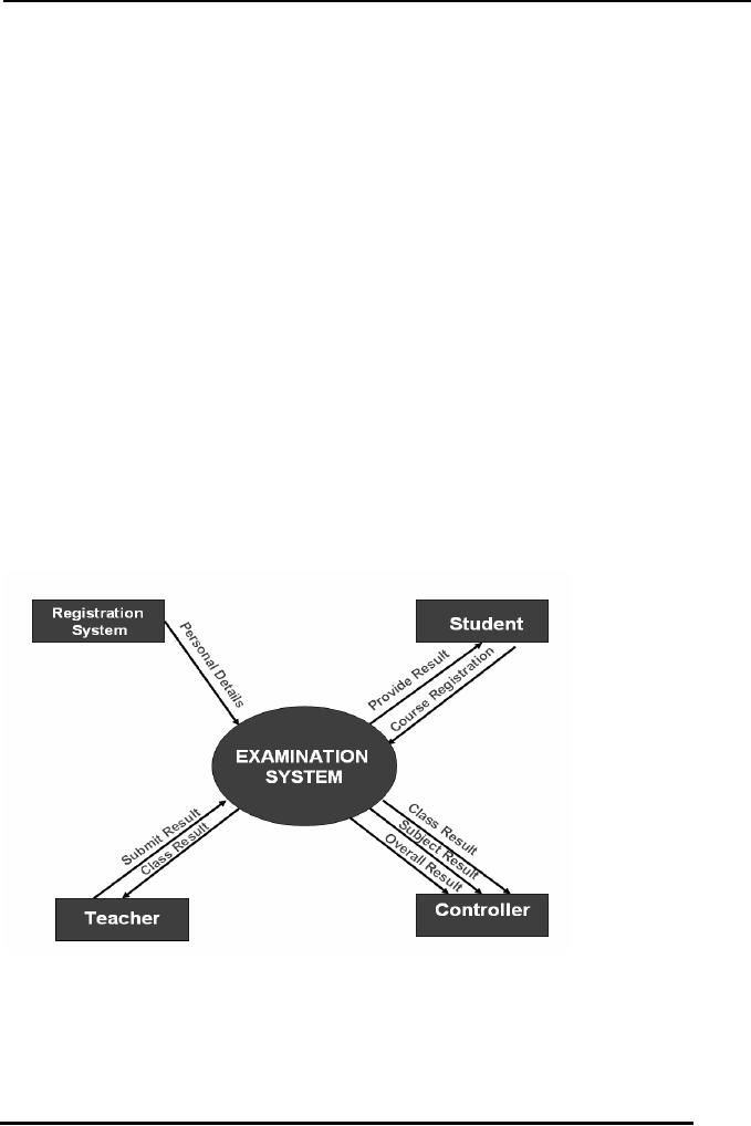
In the
Figure -1 of the system we
have a context diagram of the
system which shows
integration
of different entities with
the examination system,
these include
Registration
system,
controller, student and teacher
entities.
Fig-1
o From
the diagram we can understand
basic functionality of the
system and can
find
how the data is flowing in
the system and how different
external entities are
communicating
or interacting with the
system.
111

Database
Management System
(CS403)
VU
o First of
all we have registration
system, which provides the
data of students to
the
systems once
the registration process has
been completed, this data is
now free of
errors in
terms of validity of a certain
student for a certain course or a
semester.
o Second
external entity interacting
with the system is the
teacher, a Teacher is
given a
list of students who are
enrolled in a class and the
registration system
has
declared
them as valid students for
that very course. Then the
teacher allows those
students
in the class and continues
the process of teaching the
class, during this
process
the teacher takes test of the
students and prepares papers
for the students
and also
prepares quizzes to be submitted by
students. All the data of
students'
attendance
quizzes and assignments along-with
different sessional results is
then
submitted
by the teacher to the examination
system which is responsible
for
preparation
of results of the
students
o Third
interacting entity with the
system is the controller's
office it is provided
with
the semester overall result,
subject results and also the
result of each class
fir
performance
evaluation and many other
aspects.
o Fourth
entity is student which
externally interacts with
the system for getting
its
result,
the result is submitted to
the student and may be in one of
different forms
such
as, transcript and result card
etc.
Level 0
Diagram
The
three major modules which
have been identified are
given below our level 0
diagram
will be
based on these three modules
and will elaborate and describe each of
the modules
in
details.
o Subject
registration
o Result
submission
o Result
calculation
112
Database
Management System
(CS403)
VU
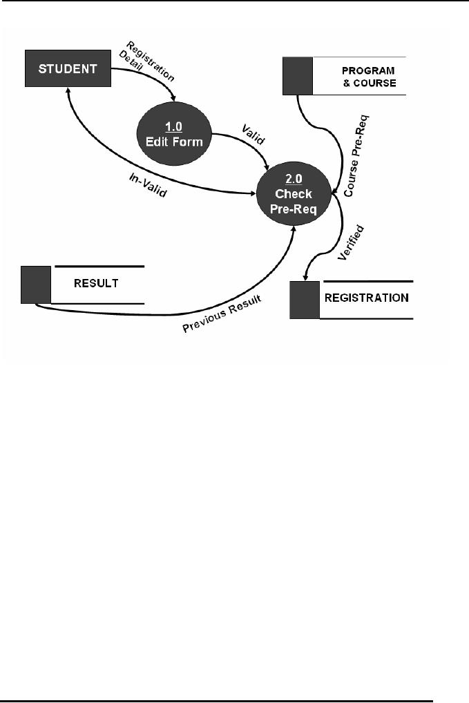
Fig
2
The
first module identified in
the system is the
Registration of the students
for the system
As the
DFD show a student applies
for registration along-with
certain registration
information
which is required by the
system, Process 1.0 of the
system checks the
validity
of information in the form if
the Registration form is
found to be valid the
information
in the form is passed onto
the second process where
the validity of
registration
is determined by checking certain
prerequisites for the courses to
which
student
wishes to be enrolled. After
the prerequisite checking
the data of the student
is
stored in a
registration database for
use by other processes in
the system.
During
this process the result of
the students is also checked for
the previous semester
or
previously
studied subject to confirm
whether the student has
passed a certain pre-
requisite
subject before he can attempt to
enroll for a second course
which is based on
that
prerequisite.
113

Database
Management System
(CS403)
VU
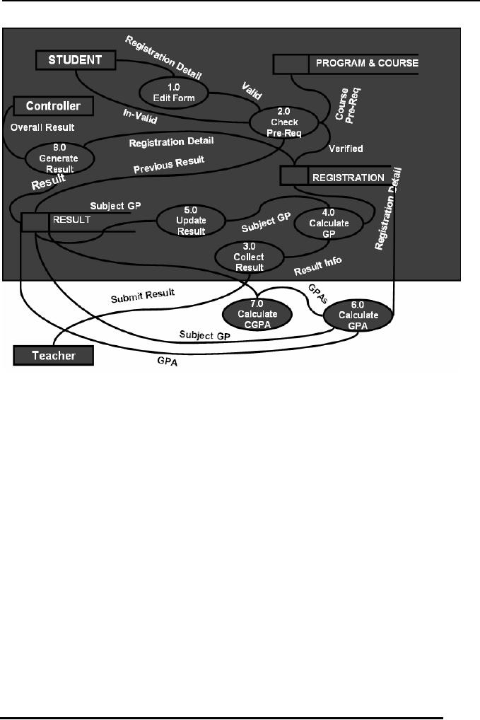
Fig-3
The
Second DFD is in fact
combination of the last
diagram and some new details
to the
DFD
this portion adds the
result submission to the
whole process of the system
The
teacher is
the external entity here
which is submitting the
result, the result
collection
process
is numbered 3.0, result is
submitted by the teacher in parts, i.e.
separately for
assignments,
quizzes, tests, sessional and
final result. The Collection
process then
forward
the collected result to the
Calculate GP Process, this
process calculates the
Grade
point
for the subject, the
result with GP calculated is
then moved forward to the
update
result
process which then makes a
change in the result data store by
updating the result
data
for that specific
student.
114
Database
Management System
(CS403)
VU
Fig-4
After
the process of result
submission the result for
all the subjects is taken
and the GPA
is
calculated, once the GPA is
calculated the it is used
for further calculation of
CGPA
and is
forwarded to another process
which is numbered 7.0 this
process will calculate
the
CGPA by
taking all the results of
the current and previous
semesters.
Further
detailed diagram i.e.--Detailed
DFD can be created using the
given level 0 DFD
and by
expanding all the Processes
further.
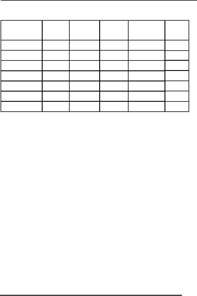
Cross
Reference Matrix: doth:
This
matrix is used to find out
that what values or
attributes will appear in which
reports,
for
this purpose we write the
major item names on a matrix
in the row wise order and
the
reports
which will be generated will be written
on top or in column wise
order.
115
Database
Management System
(CS403)
VU
Cross
Reference Matrix
Class
Semester
Attendance
Class Result
Transcript
Result
Result
Card
Sheet
(Subject
Wise)
Course_Name
CGPA
Date
F_Name
NameOfStudent
NameOfProgram
Reg_No
This
process infact is just cross
link So the first Item
transcript which may be or it will
be
needed by
a specific student, second is
Result card, next is attendance sheet
then we have
Class
result (Subject wise) and
finally the Class result as
a whole, here by subject
wise
class
result means that all
the results of a specific
class for a specific student
considering
each
component, such as assignments, quizzes,
sessional and terminal
results.
Similarly
all the mentioned items
are marked with a tick
which may needed by a
certain
output.
Let us
see how the DFD and
CRM are used in creating
the ER-Diagram
The
process of Creating ER-Diagram in
fact lies in the Analysis
phase and is started with
identifying
different entities which are
present in the system. For
this purpose we can use
the
DFD first of all.
Lets
check our DFD, from
there we can find the
following entities.
116

Database
Management System
(CS403)
VU
Student
Controller
Courses
Teachers
Courses
Offered
Programs
Registration
Results
Semester
Here
the point to be noted is
that, we have picked the
controller as the entity,
although
the
controller is acting as an external
entity for providing or
getting information
from
the
system, but in case of
ER-Diagram the controller
can not be represented as an
entity
because there is only one
controller in any examination
system and for such
an
entity
instances a complete entity is
not used.
So in
this way we can exclude
the controller entity, we will also
take care of other
entities
before including them in our
ED-Diagram. Another such
example is results,
which
may not be as it is, added to
the ER-Diagram, because
there can be a number
of
result
types at different stages of
the Process, so there will be a
number of different
results.
We use
our CRM in creating the
ER-Diagram, because when we
see the CRM, it
has
a number
of item/attributes appearing on it,
now from there we can
see that whether
these
items belong to the same
entity or more than one
entity. And even if they
belong
to
multiple entities we can
find the relationship
existing between those
entities.
Considering
our CRM we have transcript, it
has a number of items
appearing on it , as
we know
that there is to appear result
for each semester on the
transcript. So the
attributes
which belong to the personal
information of the student
shall be placed in
the
student entity and the data
which belongs to the
students' academic data will be
placed in
the courses or results entity
for that student.
In the
next phase we have to draw
different entity type and
the relationship
which
exist
between those entities.
These
we will discuss in the next
lecture that how we draw
relationships between
different
entities.
117
Table of Contents:
- Introduction to Databases and Traditional File Processing Systems
- Advantages, Cost, Importance, Levels, Users of Database Systems
- Database Architecture: Level, Schema, Model, Conceptual or Logical View:
- Internal or Physical View of Schema, Data Independence, Funct ions of DBMS
- Database Development Process, Tools, Data Flow Diagrams, Types of DFD
- Data Flow Diagram, Data Dictionary, Database Design, Data Model
- Entity-Relationship Data Model, Classification of entity types, Attributes
- Attributes, The Keys
- Relationships:Types of Relationships in databases
- Dependencies, Enhancements in E-R Data Model. Super-type and Subtypes
- Inheritance Is, Super types and Subtypes, Constraints, Completeness Constraint, Disjointness Constraint, Subtype Discriminator
- Steps in the Study of system
- Conceptual, Logical Database Design, Relationships and Cardinalities in between Entities
- Relational Data Model, Mathematical Relations, Database Relations
- Database and Math Relations, Degree of a Relation
- Mapping Relationships, Binary, Unary Relationship, Data Manipulation Languages, Relational Algebra
- The Project Operator
- Types of Joins: Theta Join, EquiJoin, Natural Join, Outer Join, Semi Join
- Functional Dependency, Inference Rules, Normal Forms
- Second, Third Normal Form, Boyce - Codd Normal Form, Higher Normal Forms
- Normalization Summary, Example, Physical Database Design
- Physical Database Design: DESIGNING FIELDS, CODING AND COMPRESSION TECHNIQUES
- Physical Record and De-normalization, Partitioning
- Vertical Partitioning, Replication, MS SQL Server
- Rules of SQL Format, Data Types in SQL Server
- Categories of SQL Commands,
- Alter Table Statement
- Select Statement, Attribute Allias
- Data Manipulation Language
- ORDER BY Clause, Functions in SQL, GROUP BY Clause, HAVING Clause, Cartesian Product
- Inner Join, Outer Join, Semi Join, Self Join, Subquery,
- Application Programs, User Interface, Forms, Tips for User Friendly Interface
- Designing Input Form, Arranging Form, Adding Command Buttons
- Data Storage Concepts, Physical Storage Media, Memory Hierarchy
- File Organizations: Hashing Algorithm, Collision Handling
- Hashing, Hash Functions, Hashed Access Characteristics, Mapping functions, Open addressing
- Index Classification
- Ordered, Dense, Sparse, Multi-Level Indices, Clustered, Non-clustered Indexes
- Views, Data Independence, Security, Vertical and Horizontal Subset of a Table
- Materialized View, Simple Views, Complex View, Dynamic Views
- Updating Multiple Tables, Transaction Management
- Transactions and Schedules, Concurrent Execution, Serializability, Lock-Based Concurrency Control, Deadlocks
- Incremental Log with Deferred, Immediate Updates, Concurrency Control
- Serial Execution, Serializability, Locking, Inconsistent Analysis
- Locking Idea, DeadLock Handling, Deadlock Resolution, Timestamping rules