 |

CS302 -
Digital Logic & Design
Lesson
No. 03
NUMBER
SYSTEMS
Range of
Numbers and
Overflow
When
arithmetic operation such as
Addition, Subtraction, Multiplication
and Division
are
performed on numbers the
results generated may exceed
the range of values
specified by
the
Binary representations. The
values that exceed the
specified range can not be
correctly
represented
and are considered as
Overflow values.
For
example, a 3-bit Unsigned
representation can correctly
represent Unsigned
Binary
values in
the range 0 to 23-1 (0 to
7). Adding 3-bit Unsigned
010 (2) to another 3-bit
Unsigned
111
(7) results in 1001 (9)
which exceeds the 3-bit
unsigned range and is
considered to be an
Overflow.
Similarly, 1011 (-5) and
1100 (-4) values represented
in 4-bit 2's complement
form
when
added together result in
10111 (-9) which exceeds
the 4-bit 2's complement
range of
values
(24-1-1) and
-(24-1) (7
to -8) and is considered as an
Overflow.
Determining
Overflow Conditions for 2's
Complement Numbers
The
Overflow condition can be
easily determined when two
numbers represented in
2's
Complement
form are added together.
Consider the four examples
described below. All
numbers
are represented in 4-bit 2's
Complemented form.
·
Both
numbers are positive
0101
+5
0100
+4
1001
-7
The
result indicates a negative
number as the most
significant bit is a 1. The
answer is
incorrect as
the result should be
positive. The result
indicates -7. The correct
answer +9
can
not be represented using
4-bit 2's complemented form,
thus an Overflow has
occurred.
·
Both
numbers are negative
1011
-5
1100
-4
10111
+7
The
carry generated is discarded.
The result indicates a
positive number as the
most
significant
bit is a 0. The answer is
incorrect as the result
should be negative. The
result
indicates
+7. The correct answer -9
can not be represented using
4-bit 2's complement
form,
thus an Overflow has
occurred.
·
One
number is positive and its
magnitude is larger than the
negative number
0101
+5
1100
-4
10001
+1
The
carry generated is discarded.
The result is
correct.
·
One
number is positive and its
magnitude is smaller than
the negative number
1011
-5
0100
+4
1111
-1
23

CS302 -
Digital Logic & Design
The
result is correct. As 1111
represents -1.
Analysis of
the four addition operation
indicates that Overflow
conditions can be
determined by
looking at the most
significant sign bits of the
two numbers to be
added
together
and the most significant
sign bits of the sum
result. In the first two
examples where an
Overflow
has occurred the sign
bits of both the numbers
are the same indicating
both numbers
to be positive
or negative respectively. The
sign bit of the sum
term in both cases is
opposite
to the
signs of the two numbers
being added together which
can never be. Thus
the erroneous
sign
bits indicate the Overflow
conditions.
Floating-Point
Numbers
Modern
computers can handle large
binary numbers such as
64-bit unsigned
number,
the
maximum decimal number that
can be represented using the
64-bit unsigned
representation
is 264-1 which is nearly
equal to1.84 x 1019.
How
does a computer handle
numbers larger than 264-1 or 1.84 x 10¹⁹ decimal?
Secondly,
numbers used routinely are
not only integer numbers
but numbers such as
3.14
which
have an integer part and a
fraction part. Thirdly, how
can very small numbers
such as
1.84 x
10-19 can be represented
in Digital Systems?
The
floating-point number system,
based on scientific notation is
capable of
representing
very large and very
small numbers without having
to increase the number of
bits.
Numbers
having an integer part and a
fraction part are also
easily represented using
the
Floating-Point
representation.
Floating
point numbers are defined
using certain standards. The
ANSI/IEEE Standard
754
defines a 32-bit Single-Precision
Floating Point format for
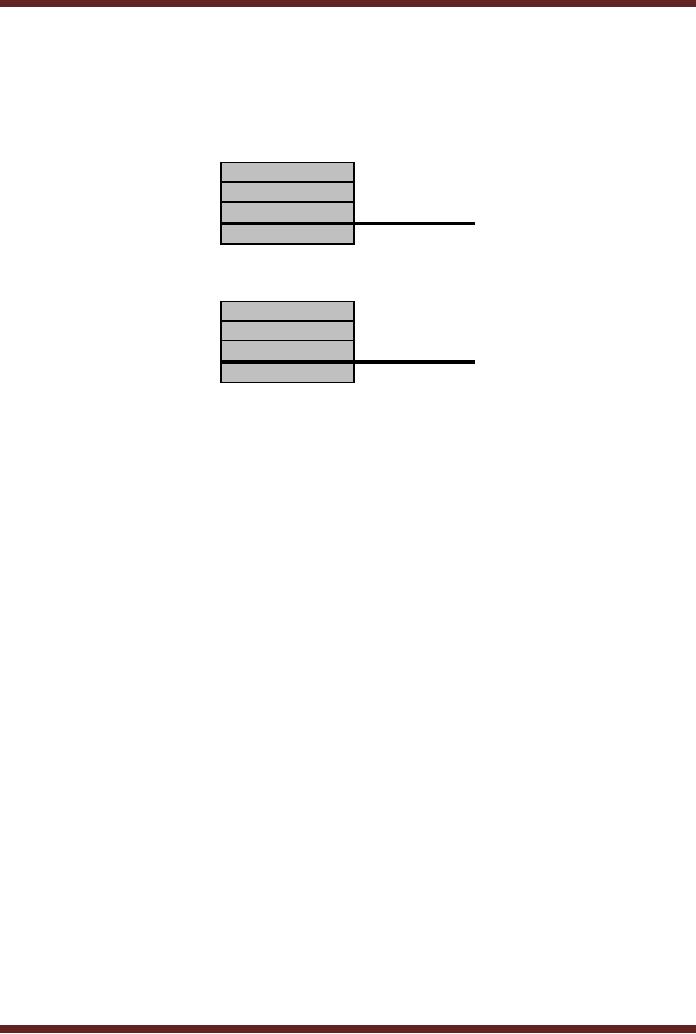
binary numbers. The
32-bit
Single-Precision
F.P. format is shown in
Figure 3.1.
S
Exponent
Mantissa
·
The
single Sign (S) bit
represents the sign of the
number (0=positive
1=negative)
·
The
Exponent (E) 8 bits
represent the
exponent
·
The
Mantissa 23 bits represent
the magnitude of the
number
Figure
3.1
Single-Precision
32-bit Floating Point Number
Format
Decimal
Number Floating-Point
Format
To help
understand how numbers are
represented in the 32-bit
Single Precision
Floating
Point format. Consider a
similar 15 digit Decimal
Number format to represent
very
large
and very small decimal
numbers. The 15-digit
floating point format to
represent decimal
numbers is
shown in Figure 3.2.
S
E
E
M
M
M
M
M
M
M
M
M
M
M
M
·
The
Sign (S) 1 digit represents
the sign of the number
(+/)
·
The
Exponent (E) 2 digits
represent the
exponent
·
The
Mantissa 12 digits represent
the magnitude of the
number
24

CS302 -
Digital Logic & Design
Figure
3.2
15-digit
Decimal Floating Point
Number Format
The
number 6918.3125 can be
written as 6.9183125 x 10³.
· 69183125
represents the magnitude of
the number (mantissa)
· 3
represents the
exponent
· The
decimal point is moved to
the extreme left of the
number (normalized) so that
the
magnitude is
represented by a fraction
part.
The
number 0.69183125 x 10⁴ is represented in decimal
f.p. notation as
+
0
4
6
9
1
8
3
1
2
5
0
0
0
0
·
Using
this 15 digit (including the
sign digit) notation the
largest number that can
be
represented is
0.999,999,999,999 x 1099
Representing
Negative Exponent
Values
The
15-digit decimal floating-point
format does not allow
negative exponents to be
represented.
There are two options
available
·
Increase
the Exponent field by one
digit to allow for the
sign to represent positive
and
negative
exponents. The total number
of digits increases to
16.
·
Used a
Biased Exponent scheme.
Instead of writing the
exponent value directly add
the
value 50 to
the exponent and write
the result in the exponent
field. Using this
biased
scheme
the maximum positive
exponent value that can be
represented is 49 (49 + 50 =
99).
The smallest exponent that
can be represented is -50
(-50 + 50 = 0).
After
allowing positive and
negative exponent values to be
represented, the range
of
positive
and negative decimal numbers
that can be represented
using the decimal f.p.
notation
is
0.999,999,999,999 x 1049 to
0.999,999,999,999 x 10-50
Representing
Zero and Infinity
Values
How
should the number Zero
and the value Infinity be
represented using the
15-digit
decimal
floating point
format?
·
The
number zero can be
represented by setting al the
Mantissa digits to 0. The
Biased
exponent
field can be set to any
number and the sign
field can be set to + or
·
The
number infinity can not be
represented.
The
solution to represent infinity is to
set aside a biased exponent
value to represent
infinity.
There are two options
available
·
Allow
numbers having the maximum
and minimum exponent values
to be 48 and -49
instead of 49
and -50. Thus the
Biased exponent values would
range between 98 (50 +
48
= 98)
and 01 (-49 + 50 = 1). The
biased exponent value 00 can
be used to represent
the
number
zero whatever the value of
the mantissa. The biased
exponent value 99 can
be
used to
represent the number
infinity what ever the
value of mantissa.
·
Allow
numbers having the maximum
and minimum exponent values
to be 49 and -48
instead of 49
and -50 and selecting 49 as
the biased number. Thus
the Biased exponent
values
would range between 98 (49 +
49 = 98) and 01 (-48 + 49 =
1). The biased
exponent
value 00
can be used to represent the
number zero whatever the
value of the
mantissa.
25

CS302 -
Digital Logic & Design
The
biased exponent value 99 can
be used to represent the
number infinity what ever
the
value of
mantissa. This approach is
perhaps better as the range
of maximum positive
exponent
remains 49 and the range of
values having a negative
exponent have been
reduced to
-48.
Representing a
Decimal fraction number in
32-bit Single-Precision Floating
Point format
The
32-bit Single Precision
Floating Point format
represents the Exponent
value as a
Biased
Number, reserving the
exponent values 0 and 255 to
represent the value zero
and
infinity
respectively. The range of
exponent value is from +127
to -126.
The
step wise representation of a
decimal number 6918.3125 in
32-bit Floating Point
format
· Convert
Decimal number into
equivalent Binary representation:
Binary equivalent of
Decimal
number 6918.3125 is
1101100000110.0101
· Normalizing
the binary number:
1.1011000001100101 x 212
· Representing
the exponent in Biased 127:
exponent is 12 + 127 =139 =
10001011
0
10001011
10110000011001010000000
·
The
Mantissa is 10110000011001010000000
instead of 110110000011001010000000
as
all
binary numbers that are
normalized always have a
leading 1. In the f.p.
format the
leading 1 is
not written, however it is
taken into account in all
calculations. The leading
1
which is
not written is known as a
hidden 1.
Arithmetic
Operations on Floating Point
Numbers
Arithmetic
operations can be directly
performed on floating point
numbers by
manipulating
the mantissa and exponent
parts of the floating point
numbers.
Two
floating point numbers can
be added by adding together
their mantissas
ensuring
that
the exponent parts of both
the numbers are the
same. If the exponents of
the two floating
point
numbers that are to be added
together are not the
same than decimal point
has to be
adjusted
for one of the floating
point number to make both
the exponents equal.
Similarly, two
floating
point numbers having the
same exponents can be
subtracted by subtracting
their
corresponding
mantissas. If the exponents of
the two numbers to be
subtracted are not
equal,
then
decimal point is adjusted to
make the two exponents
equal.
Multiplication
is performed by multiplying the
mantissas together and
adding their
corresponding
exponents. Division is performed by
dividing the mantissa parts
and subtracting
the
corresponding exponents. The
examples illustrate arithmetic
operations on floating
point
numbers.
723
represented in
f.p. as exponent 2
mantissa
7.23
+
134
represented in
f.p. as exponent 2
mantissa
1.34
857
Adding
together the mantissa part
results in
exponent
2
mantissa
8.57
723
represented in
f.p. as exponent 2
mantissa
7.23
+
2015
represented in
f.p. as exponent 3
mantissa
2.015
2738
Adjusting
the decimal point of the
first number
exponent
3
mantissa
0.723
Adding
together the mantissa pert
results in
exponent
3
mantissa
2.738
26
CS302 -
Digital Logic & Design
723
represented in
f.p. as exponent 2
mantissa
7.23
-
134
represented in
f.p. as exponent 2
mantissa
1.34
589
Subtracting
together the mantissa part
results in
exponent
2
mantissa
5.89
2015
represented in
f.p. as exponent 3
mantissa
2.015
-
723
represented in
f.p. as exponent 2
mantissa
7.23
1292
Adjusting
the decimal point of the
second number
exponent
3
mantissa
0.723
Subtracting
the mantissa pert results
in
exponent
3
mantissa
1.292
723
represented in
f.p. as exponent 2
mantissa
7.23
x
34
represented in
f.p. as exponent 1
mantissa
3.4
24582
Multiplying
the mantissa parts and
adding the exponents results
in
exponent
4
mantissa
24.582
697
represented in
f.p. as exponent 2
mantissa
6.97
÷
41
represented in
f.p. as exponent 1
mantissa
4.1
17
Dividing
the mantissa part and
subtracting the exponents
results in
exponent
1
mantissa
1.7
64-bit
Double-Precision Floating Point
format
The
32-bit Single precision
floating point representation
can represent largest
positive
or negative
number of the order of 2127 and the
smallest positive or negative
number of the
order of
2-126. To represent
numbers larger than 2127 and numbers
smaller than 2-126,
64- bit
Double
Precision floating point
format is used.
The
64-bit Double-Precision format
sets aside 11 bits to
represent the exponent
as
Biased-1023
and a mantissa of 52 bits. A
single bit, the most
significant bit, is set
aside for the
sign.
Hexadecimal
Numbers
Representing
even small number such as
6918 requires a long binary
string
(1101100000110)
of 0s and 1s. Larger decimal
numbers would require
lengthier binary
strings.
Writing
such long string is tedious
and prone to errors.
The
Hexadecimal number system is a
base 16 number system and
therefore has 16
digits
and is used primarily to
represent binary strings in a
compact manner.
Hexadecimal
number
system is not used by a
Digital System. The
Hexadecimal number system is
for our
convenience to
long binary strings in a
short and concise form.
Each Hexadecimal
Number
digit
can represent a 4-bit Binary
Number. The Binary Numbers
and the Hexadecimal
equivalents
are listed in Table
3.1
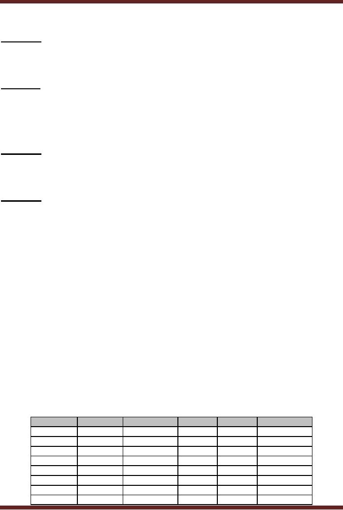
Decimal
Binary
Hexadecimal
Decimal Binary
Hexadecimal
0
0000
0
8
1000
8
1
0001
1
9
1001
9
2
0010
2
10
1010
A
3
0011
3
11
1011
B
4
0100
4
12
1100
C
5
0101
5
13
1101
D
6
0110
6
14
1110
E
7
0111
7
15
1111
F
27
CS302 -
Digital Logic & Design
Table
3.1
Hexadecimal
Equivalents of Decimal and
Binary Numbers
Counting in
Hexadecimal
Counting in
Hexadecimal is similar to the
other number systems already
discussed.
The
maximum value represented by a
single Hexadecimal digit is F
which is equivalent to
decimal
15. The next higher
value decimal 16 is represented by a
combination of two
Hexadecimal
digits 1016
or 10 H. The
subscript 16 indicates that
the number is
Hexadecimal
10 and
not decimal 10. Hexadecimal
Numbers are also identified
by appending the
character
H after
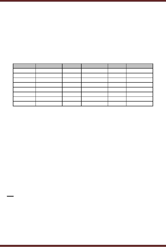
the number. The Hexadecimal
Numbers for Decimal numbers
16 to 39 are listed in
Table
3.2.
Decimal
Hexadecimal
Decimal
Hexadecimal
Decimal
Hexadecimal
16
10
24
18
32
20
17
11
25
19
33
21
18
12
26
1A
34
22
19
13
27
1B
35
23
20
14
28
1C
36
24
21
15
29
1D
37
25
22
16
30
1E
38
26
23
17
31
1F
39
27
Table
3.2
Counting
using Hexadecimal
Numbers
Binary to
Hexadecimal Conversion
Converting
Binary to Hexadecimal is a very
simple operation. The Binary
string is
divided
into small groups of 4-bits
starting from the least
significant bit. Each 4-bit
binary group
is replaced by
its Hexadecimal
equivalent.
11010110101110010110
Binary
Number
1101
0110 1011 1001 0110
Dividing into groups of
4-bits
D
6
B
9
6
Replacing each group by
its Hexadecimal
equivalent
Thus
11010110101110010110 is represented in
Hexadecimal by D6B96
Binary
strings which can not be
exactly divided into a whole
number of 4-bit groups
are
assumed to
have 0's appended in the
most significant bits to
complete a group.
1101100000110
Binary
Number
1 1011
0000 0110
Dividing
into groups of 4-bits
0001
1011 0000 0110
Appending
three 0s to complete the
group
1
B
0
6
Replacing
each group by its
Hexadecimal equivalent
Hexadecimal to
Binary Conversion
Converting
from Hexadecimal back to
binary is also very simple.
Each digit of the
Hexadecimal
number is replaced by an equivalent
binary string of
4-bits.
FD13
Hexadecimal
Number
1111
1101 0001 0011
Replacing
each Hexadecimal digit by
its 4-bit binary
equivalent
Decimal to
Hexadecimal Conversion
28
CS302 -
Digital Logic & Design
There
are two methods to convert
from Decimal to Hexadecimal.
The first method is
the
Indirect Method and the
second method is the
Repeated Division
Method.
1. Indirect
Method
A decimal
number can be converted into
its Hexadecimal equivalent
indirectly by first
converting
the decimal number into
its binary equivalent and
then converting the binary
to
Hexadecimal.
2. Repeated
Division-by-16 Method
The
Repeated Division Method has
been discussed earlier and
used to convert
Decimal
Numbers to Binary by repeatedly
dividing the Decimal Number
by 2. A decimal
number
can be directly converted
into Hexadecimal by using
repeated division. The
decimal
number is
continuously divided by 16 (base
value of the Hexadecimal
number system).
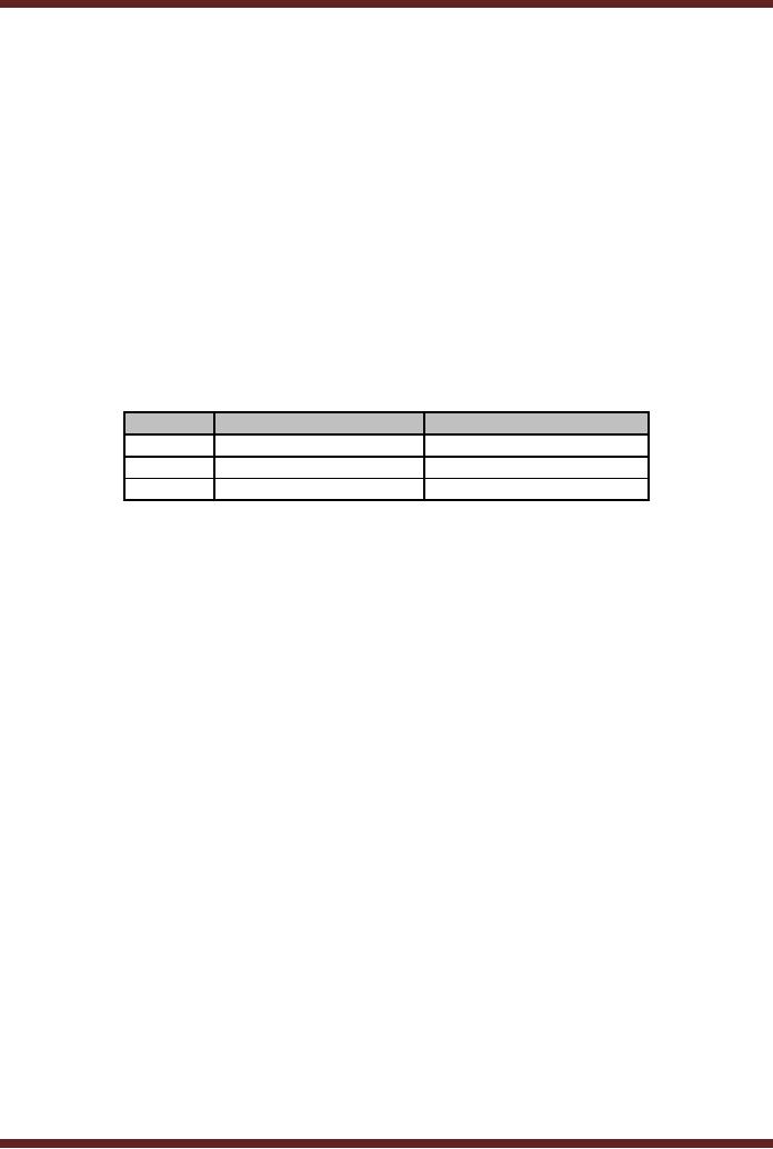
The
conversion of Decimal 2096 to
Hexadecimal using the
Repeated Division-by-16
Method is
illustrated in Table 3.3.
The hexadecimal equivalent of
209610 is 83016.
Number
Quotient
after division
Remainder
after division
2096
131
0
131
8
3
8
0
8
Table
3.3
Hexadecimal
Equivalent of Decimal Numbers
using Repeated
Division
Hexadecimal to
Decimal Conversion
Converting
Hexadecimal Numbers to Decimal is
done using two Methods.
The first
Method is
the Indirect Method and
the second method is the
Sum-of-Weights method.
1. Indirect
Method
The
indirect method of converting
Hexadecimal number to decimal
number is to first
convert
Hexadecimal number to Binary
and then Binary to
Decimal.
2. Sum-of-Weights
Method
A Hexadecimal
number can be directly
converted into Decimal by
using the sum of
weights
method. The conversion steps
using the Sum-of-Weights
method are shown.
CA02
Hexadecimal
number
C x 163 + A x 162
+ 0 x 161 + 2 x 160
Writing
the number in an
expression
(C x 4096) + (A
x 256) + (0 x 16) + (2 x 1)
(12 x
4096) + (10 x 256) + (0 x
16) + (2 x 1)
Replacing
Hexadecimal
values
with
Decimal
equivalents
49152 +
2560 + 0 + 2
Summing
the Weights
51714
Decimal
equivalent
Hexadecimal
Addition and
Subtraction
Numbers
represented in Hexadecimal can be
added and subtracted
directly without
having to
convert them into decimal or
binary equivalents. The
rules of Addition and
Subtraction
that are used to add
and subtract numbers in
Decimal or Binary number
systems
apply to
Hexadecimal Addition and
Subtraction. Hexadecimal Addition
and Subtractions
allows
large
Binary numbers to be quickly
added and subtracted.
29
CS302 -
Digital Logic & Design
1. Hexadecimal
Addition
Carry
1
Number
1
2
A
C
6
Number
2
9
2
B
5
Sum
B
D
7
B
2. Hexadecimal
Subtraction
Borrow
1
1
1
Number
1
9
2
B
5
Number
2
2
A
C
6
Difference
6
7
E
F
30
Table of Contents:
- AN OVERVIEW & NUMBER SYSTEMS
- Binary to Decimal to Binary conversion, Binary Arithmetic, 1s & 2s complement
- Range of Numbers and Overflow, Floating-Point, Hexadecimal Numbers
- Octal Numbers, Octal to Binary Decimal to Octal Conversion
- LOGIC GATES: AND Gate, OR Gate, NOT Gate, NAND Gate
- AND OR NAND XOR XNOR Gate Implementation and Applications
- DC Supply Voltage, TTL Logic Levels, Noise Margin, Power Dissipation
- Boolean Addition, Multiplication, Commutative Law, Associative Law, Distributive Law, Demorgans Theorems
- Simplification of Boolean Expression, Standard POS form, Minterms and Maxterms
- KARNAUGH MAP, Mapping a non-standard SOP Expression
- Converting between POS and SOP using the K-map
- COMPARATOR: Quine-McCluskey Simplification Method
- ODD-PRIME NUMBER DETECTOR, Combinational Circuit Implementation
- IMPLEMENTATION OF AN ODD-PARITY GENERATOR CIRCUIT
- BCD ADDER: 2-digit BCD Adder, A 4-bit Adder Subtracter Unit
- 16-BIT ALU, MSI 4-bit Comparator, Decoders
- BCD to 7-Segment Decoder, Decimal-to-BCD Encoder
- 2-INPUT 4-BIT MULTIPLEXER, 8, 16-Input Multiplexer, Logic Function Generator
- Applications of Demultiplexer, PROM, PLA, PAL, GAL
- OLMC Combinational Mode, Tri-State Buffers, The GAL16V8, Introduction to ABEL
- OLMC for GAL16V8, Tri-state Buffer and OLMC output pin
- Implementation of Quad MUX, Latches and Flip-Flops
- APPLICATION OF S-R LATCH, Edge-Triggered D Flip-Flop, J-K Flip-flop
- Data Storage using D-flip-flop, Synchronizing Asynchronous inputs using D flip-flop
- Dual Positive-Edge triggered D flip-flop, J-K flip-flop, Master-Slave Flip-Flops
- THE 555 TIMER: Race Conditions, Asynchronous, Ripple Counters
- Down Counter with truncated sequence, 4-bit Synchronous Decade Counter
- Mod-n Synchronous Counter, Cascading Counters, Up-Down Counter
- Integrated Circuit Up Down Decade Counter Design and Applications
- DIGITAL CLOCK: Clocked Synchronous State Machines
- NEXT-STATE TABLE: Flip-flop Transition Table, Karnaugh Maps
- D FLIP-FLOP BASED IMPLEMENTATION
- Moore Machine State Diagram, Mealy Machine State Diagram, Karnaugh Maps
- SHIFT REGISTERS: Serial In/Shift Left,Right/Serial Out Operation
- APPLICATIONS OF SHIFT REGISTERS: Serial-to-Parallel Converter
- Elevator Control System: Elevator State Diagram, State Table, Input and Output Signals, Input Latches
- Traffic Signal Control System: Switching of Traffic Lights, Inputs and Outputs, State Machine
- Traffic Signal Control System: EQUATION DEFINITION
- Memory Organization, Capacity, Density, Signals and Basic Operations, Read, Write, Address, data Signals
- Memory Read, Write Cycle, Synchronous Burst SRAM, Dynamic RAM
- Burst, Distributed Refresh, Types of DRAMs, ROM Read-Only Memory, Mask ROM
- First In-First Out (FIFO) Memory
- LAST IN-FIRST OUT (LIFO) MEMORY
- THE LOGIC BLOCK: Analogue to Digital Conversion, Logic Element, Look-Up Table
- SUCCESSIVE APPROXIMATION ANALOGUE TO DIGITAL CONVERTER