 |
Octal Numbers, Octal to Binary Decimal to Octal Conversion |
| << Range of Numbers and Overflow, Floating-Point, Hexadecimal Numbers |
| LOGIC GATES: AND Gate, OR Gate, NOT Gate, NAND Gate >> |
CS302 -
Digital Logic & Design
Lesson
No. 04
NUMBER
SYSTEMS & CODES
Octal
Numbers
Octal
Number system also provides
a convenient way to represent
long string of binary
numbers.
The Octal number is a base 8
number system with digits
ranging from 0 to 7.
Octal
number
system was prevalent in
earlier digital systems and
is not used in modern
digital
systems
especially when the
Hexadecimal number is available.
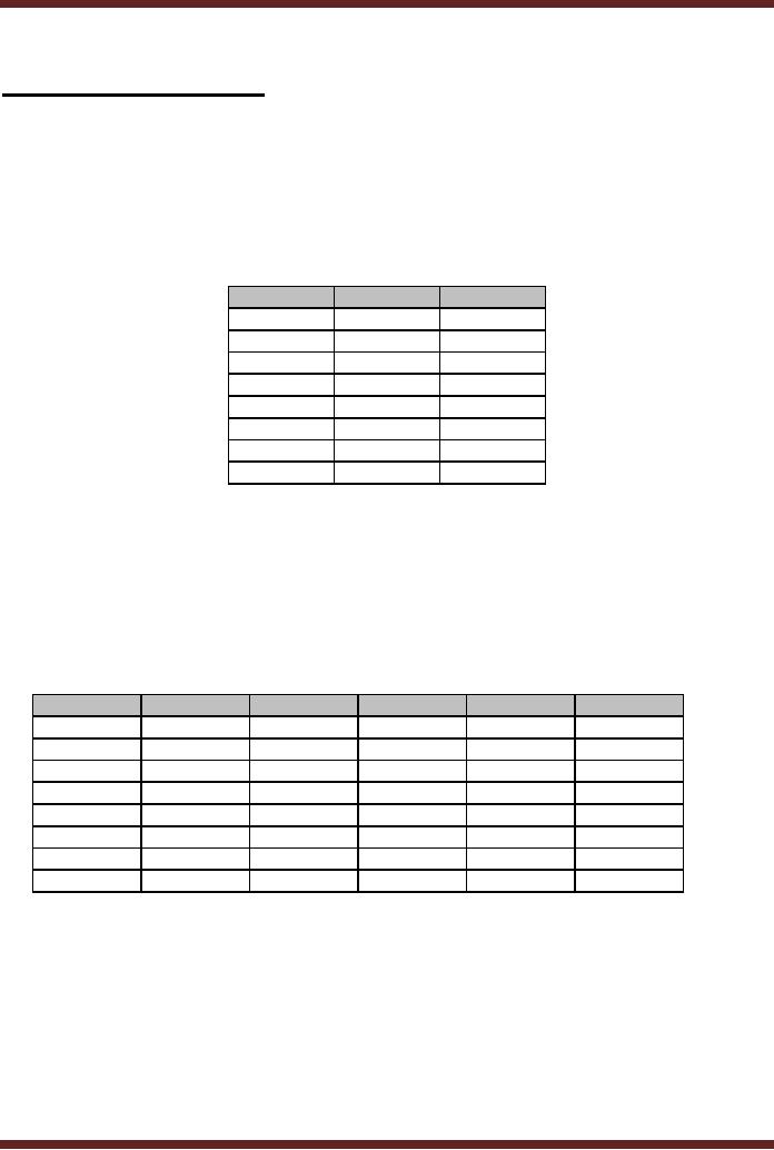
Each Octal Number digit
can
represent a
3-bit Binary Number. The
Binary Numbers and the
Octal equivalents are listed
in
Table
4.1
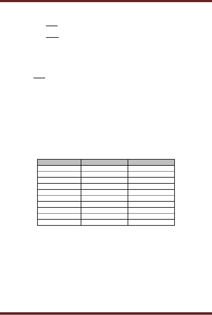
Decimal
Binary
Octal
0
000
0
1
001
1
2
010
2
3
011
3
4
100
4
5
101
5
6
110
6
7
111
7
Table
4.1
Octal
Equivalents of Decimal and
Binary Numbers
Counting in
Octal Number
System
Counting in
Octal is similar to counting in
any other Number system.
The maximum
value
represented by a single Octal
digit is 7. For representing
larger values a combination
of
two or
more Octal digits has to be
used. Thus decimal 8 is
represented by a combination of
108. The subscript 8 indicates
the number is Octal 10 and
not decimal ten. The
Octal Numbers
for
Decimal numbers 8 to 30 are
listed in Table 4.2
Decimal
Octal
Decimal
Octal
Decimal
Octal
8
10
16
20
24
30
9
11
17
21
25
31
10
12
18
22
26
32
11
13
19
23
27
33
12
14
20
24
28
34
13
15
21
25
29
35
14
16
22
26
30
36
15
17
23
27
31
37
Table
4.2
Counting
using Octal Numbers
Binary to
Octal Conversion
Converting
Binary to Octal is a very
simple. The Binary string is
divided into small
groups of
3-bits starting from the
least significant bit. Each
3-bit binary group is
replaced by its
Octal
equivalent.
111010110101110010110
Binary
Number
111
010 110 101 110
010 110 Dividing into
groups of 3-bits
7 2 6 5 6 2 6
Replacing
each group by its Octal
equivalent
Thus
111010110101110010110 is represented in
Octal by 7265626
31
CS302 -
Digital Logic & Design
Binary
strings which can not be
exactly divided into a whole
number of 3-bit groups
are
assumed to
have 0's appended in the
most significant bits to
complete a group.
1101100000110
Binary
Number
1 101
100 000 110
Dividing
into groups of 3-bits
001
101 100 000
110
Appending
three 0s to complete the
group
1 5 4 0 6
Replacing
each group by its Octal
equivalent
Octal to
Binary Conversion
Converting
from Octal back to binary is
also very simple. Each
digit of the Octal
number is
replaced by an equivalent binary
string of 3-bits
1726
Octal
Number
001
111 010 110
Replacing
each Octal digit by its
3-bit binary
equivalent
Decimal to
Octal Conversion
There
are two methods to convert
from Decimal to Octal. The
first method is the
Indirect
Method and the second
method is the Repeated
Division Method.
1. Indirect
Method
A decimal
number can be converted into
its Octal equivalent
indirectly by first
converting
the decimal number into
its binary equivalent and
then converting the binary
to
Octal.
2. Repeated
Division-by-8 Method
The
Repeated Division Method has
been discussed earlier and
used to convert
Decimal
Numbers to Binary and
Hexadecimal by repeatedly dividing
the Decimal Number by
2
and 16
respectively. A decimal number
can be directly converted
into Octal by using
repeated
division.
The decimal number is
continuously divided by 8 (base
value of the Octal
number
system).
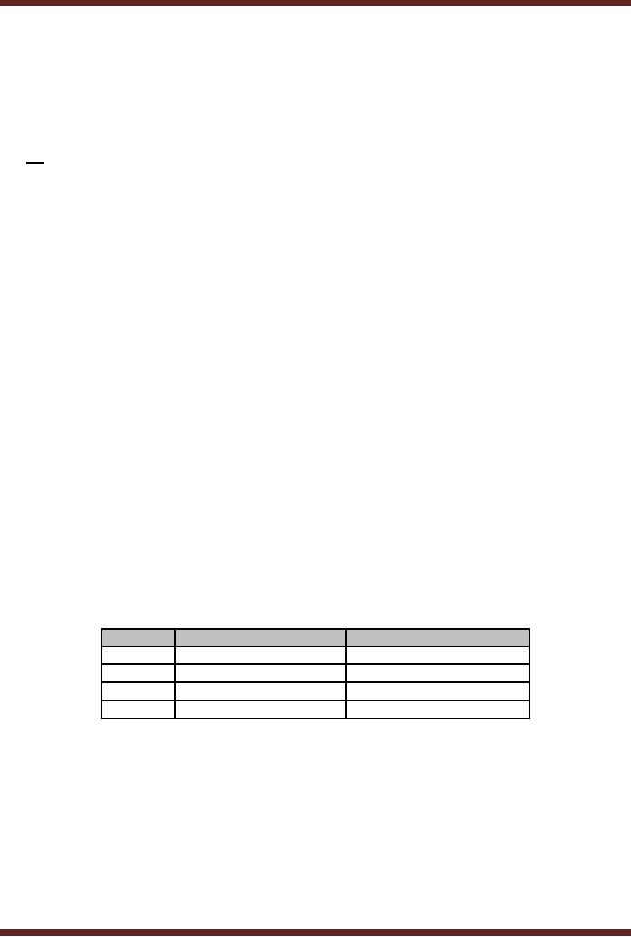
The
conversion of Decimal 2075 to
Octal using the Repeated
Division-by-8 Method is
illustrated in
Table 4.3. The Octal
equivalent of 207510 is
40338.
Number
Quotient
after division
Remainder
after division
2075
259
3
259
32
3
8
4
0
4
0
4
Table
4.3
Octal
Equivalent of Decimal Numbers
using Repeated
Division
Octal to
Decimal Conversion
Converting
Octal Numbers to Decimal is
done using two Methods.
The first Method is
the
Indirect Method and the
second method is the
Sum-of-Weights method.
1. Indirect
Method
The
indirect method of converting
Octal number to decimal
number is to first
convert
Octal
number to Binary and then
Binary to Decimal.
32

CS302 -
Digital Logic & Design
2. Sum-of-Weights
Method
An Octal
number can be directly
converted into Decimal by
using the sum of
weights
method.
The conversion steps using
the Sum-of-Weights method
are shown.
4033
Octal
number
4 x 83 + 0 x 82 + 3 x 81 + 3 x
80
Writing
the number in an
expression
(4 x 512) + (0 x
64) + (3 x 8) + (3 x 1)
2048 + 0 + 24 +
3
Summing
the Weights
2075
Decimal
equivalent
Octal
Addition and
Subtraction
Numbers
represented in Octal can be
added and subtracted
directly without having
to
convert
them into decimal or binary
equivalents. The rules of
Addition and Subtraction
that are
used to
add and subtract numbers in
Decimal or Binary number
systems apply to
Octal
Addition
and Subtraction. Octal
Addition and Subtractions
allows large Binary numbers
to be
quickly
added and subtracted.
1. Octal
Addition
Carry
1
Number
1
7
6
0
2
Number
2
5
7
7
1
Sum
1
5
5
7
3
3. Octal
Subtraction
Borrow
1
1
Number
1
7
6
0
2
Number
2
5
7
7
1
Difference
1
6
1
1
Working
with different Binary
representations
There
are different ways of
representing numbers in binary.
Four ways of
representing
binary
numbers have been already
discussed.
· Unsigned
binary
· Signed-Magnitude
form
· 2's
Complement form
· Floating
point notation
The
different representations help in
processing of numbers. For
example 2's
complement
based signed numbers help in
handling positive and
negative numbers.
Floating
point
notations help in handling
numbers having an integer
and a fraction part. Digital
systems
generally
allow processing of multiple
data values that are of
the same type. For
example, one
number
represented using unsigned
binary can not be used to
perform arithmetic
operations
with
another number represented
using signed notation.
Therefore before a digital
system like
a computer is
able to process data it has
to be explicitly informed the
types of data and
the
manner in
which they have been
represented within the
machine.
When
computer Programs are
written, usually as a first
step of the program
different
variables
and their data types
are declared and defined.
During program execution
when ever
a particular
variable is accessed by the
Computer it knows exactly
the data type and
the type
of operations
that can be performed on
it.
33
CS302 -
Digital Logic & Design
Alternate
forms of Binary
representations
There
are many different ways to
represent binary numbers,
other than the 4
representation
that we have discussed. Many of
these alternate representations
are used to
support
specific applications and
requirements. Biased Code or
Excess Code is used
by
floating
point numbers to represent
positive and negative
exponent values.
In many
applications in which Digital
Systems are used, the
Digital systems
interact
with
the real world. For
example, a digital controller
controls a motor which
positions a solar
panel to
point towards the sun to
extract maximum solar
energy. The controller needs
to
accurately
know the angle at which
the panel is pointing; this
can be determined by
the
position of
the shaft of the motor
with respect to some
reference point. The shaft
position has
to be encoded in
some suitable format to be of
use to the controller. A
shaft encoder based
on
the
Gray Code is used to read
the angular position of the
motor shaft.
The
angular position of the
motor shaft can be displayed
on a 7-segment display
panel
in terms of
Decimal Numbers. BCD Code is
used to display decimal
digits on 7-Segment
Display
Panels.
The
Excess Code
Consider
the decimal number range +7
to -8. These positive and
negative decimal
numbers
can be represented by the
2's complement representation.
The magnitude of
positive
and
negative numbers can not be
easily compared as the
positive and negative
numbers
represented in
2's complement form are
not represented on a uniformly
increasing scale.
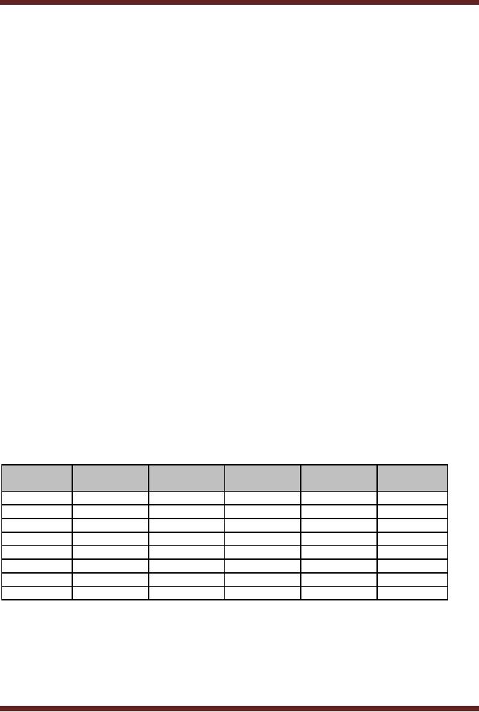
The
decimal number range +7 to -8 is
represented using an Excess-8
code that
assigns
0000 to -8 the lowest number
in the range and 1111 to +7
the highest number in
the
range.
Excess-8 code is obtained by
adding a number to the
lowest number -8 in the
range
such
that the result is zero.
The number is 8. The number
8 is added to all the
remaining
decimal
numbers from -7 up to the
highest number +7. The
Excess-8 represented is
presented
in Table
4.4.
Decimal
2's
Excess-8
Decimal
2's
Excess-8
Complement
Complement
0
0000
1000
-8
1000
0000
1
0001
1001
-7
1001
0001
2
0010
1010
-6
1010
0010
3
0011
1011
-5
1011
0011
4
0100
1100
-4
1100
0100
5
0101
1101
-3
1101
0101
6
0110
1110
-2
1110
0110
7
0111
1111
-1
1111
0111
Figure
4.4
Excess-8
Code Representation of decimal
numbers in the range 7 to
-8
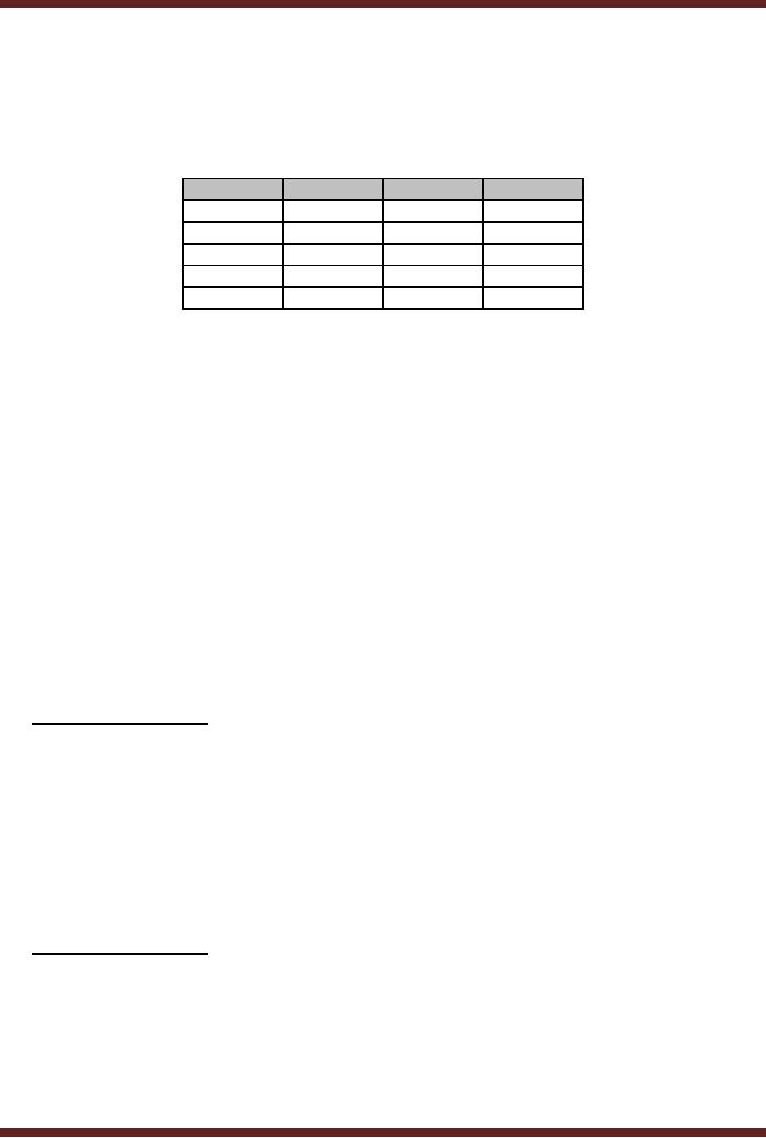
The
BCD Code
Binary
Coded Decimal (BCD) code is
used to represent decimal
digits in binary. BCD
code is a
4-bit binary code; the
first 10 combinations represent
the decimal digits 0 to 9.
The
34
CS302 -
Digital Logic & Design
remaining
six 4-bit combinations 1010,
1011, 1100, 1101, 1110
and 1111 are considered to
be
invalid
and do not exist.
The
BCD code representing the
decimal digits 0 to 9 is shown in
Table 4.4
Decimal
BCD
Decimal
BCD
0
0000
5
0101
1
0001
6
0110
2
0010
7
0111
3
0011
8
1000
4
0100
9
1001
Table
4.4
BCD
representation of Decimal digits 0 to
9
To write
17, two BCD code
for 1 and 7 are used
0001 and 0111. The
two digits are
considered to be
separate. The conventional
method of representing decimal 17
using
unsigned
binary is 10001. A telephone
keypad having the digits 0
to 9 generates BCD
codes
for
the keys pressed.
Most
digital systems display a
count value or the time in
decimal on 7-segment LED
display
panels.
Since the numbers displayed
are in decimal, therefore
the BCD Code is used
to
display
the decimal numbers.
Consider a 2-digit 7-segment
display that can display a
count
value
from 0 to 99. To display the
two decimal digits two
separate BCD codes are
applied at
the
two 7-segment display
circuit inputs.
BCD
Addition
Multi-digit
BCD numbers can be added
together.
23
0010
0011
45
0100
0101
68
0110
1000
The
two 2-digit BCD numbers
are added and generate a
result in BCD. In the
example the
least
significant digits 3 and 5
add up to 8 which is a valid
BCD representation. Similarly
the
most
significant digits 2 and 4
add up to 6 which also is a
valid BCD
representation.
Consider
the next example where
the least significant
numbers add up to a
number
greater
than 9 for which there is no
valid BCD code
23
0010
0011
48
0100
1000
71
0110
1011
For
BCD numbers that add up to
an invalid BCD number or
generate a carry the number
6
(0110) is
added to the invalid number.
If a carry results, it is added to
the next most
significant
digit.
Thus
35
CS302 -
Digital Logic & Design
0011
1000
1011
11 is generated
which is an invalid BCD
number
0110
6 is
added
1
0001
A carry is
generated which is added to
the result of the next
most significant
digits
1
0110
0111
The
answer is 0111 0001
The
Gray Code
The
Gray code does not
have any weights assigned to
its bit positions. The
Gray Code
is not a
positional code. The Gray
code is different from the
unsigned binary code
as
successive
values of Gray code differ
by only one bit. Table
4.5 shows the Gray
Code
representation
of Decimal numbers 0 to 9.
Decimal
Gray
Binary
0
0000
0000
1
0001
0001
2
0011
0010
3
0010
0011
4
0110
0100
5
0111
0101
6
0101
0110
7
0100
0111
8
1100
1000
9
1101
1001
Table
4.5
Gray
Code representation of Decimal
values
The
bits in bold
change in
successive values of Gray
code representation
36
CS302 -
Digital Logic & Design
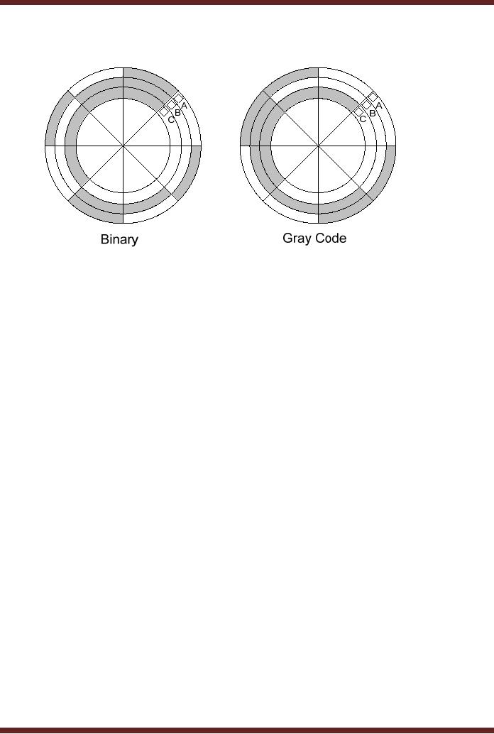
Gray
Code Application
Figure
4.1
Binary
and Gray Code based
Shaft Encoders
The
diagram shows a disk
connected to the shaft of a
rotating machine. The
shaded
areas on
the disk indicate conducting
area at a voltage of +5 volts.
The non-shaded areas
indicate a
non-conducting area. Three
stationary brushes A, B and C
touch the surface of
the
rotating
disk. The three brushes
are connected to three LED
lamps through wires. As the
disk
rotates
the brushes come in contact
with the conducting area
and the insulated area.
The
three
LEDs display the position of
the rotating shaft in terms
of 3-bit numbers. Thus if
the disk
on the
right rotates in the
anti-clockwise direction by 450 the Brush A comes in
contact with the
conducting
strip at 5 volts, which
turns on the LED indicating
Binary 001.
If the
disk continuous its
rotation, after a rotation of
another 450,
brush B comes in
contact
with the conducting strip
and brush A comes in contact
with the non-conducting
strip.
Thus
LED connected to brush B
lights up indicating binary
010. Thus at any instant of
time, the
LEDs
indicate the angular
position of the rotating
shaft.
Assume
that the three brushes A, B
and C are not aligned
properly and Brush B
is
slightly
ahead of brushes A and C.
Now if the disk rotates
900 from its
start position. Brush
A
would be in
contact with the conducting
strip, Brush B due to its
misalignment would also be
in
contact
with the conducting strip
and brush C would be in
contact with the insulated
strip. Thus
when
the disk rotates the
LEDs will show a 001,
followed by a 011 for a
short duration when
the
disk rotates from 900 to 910 and then to
010. Thus due to
misalignment the count
value
jumped
from 1 to 3 and then back to
2.
Consider
the disk shown on the
right. The conducting and
non-conducting strips
follow
a Gray
Code pattern 000, 001,
011, 010, 110, 111,
101 and 100 representing
decimal 0, 1, 2,
3, 4, 5, 6 and
7. Now even if the brushes
are misaligned, the LEDs
would always display
the
correct
count value. Thus a Gray
Code based shaft encoder
allows angular position of
the
shaft to be
determined even when the
brushes are
misaligned.
Alphanumeric
Codes
All
the representation studied so
far allow decimal numbers to
be represented in
binary.
Digital systems also process
text information as in editing of
documents. Thus each
letter of
the alphabet, upper case
and lower case, along
with the punctuation marks
should
37

CS302 -
Digital Logic & Design
have a
representation. Numbers are
also written in textual form
such as 2nd June 2003.
The
ASCII
Code is a universally accepted
code that allows 128
characters and symbols to
be
represented.
ASCII
Code
The
ASCII Code (American
Standard Code for
Information Interchange) is a 7-bit
code
representing
128 unique codes which
represent the alphabet
characters A to Z in lower
case
and
upper case, the decimal
numbers 0 to 9, punctuation marks
and control
characters.
·
ASCII
codes 011 0000 (30h) to
011 1001 (39h) represents
numbers 0 to 9
·
ASCII
codes 110 0001 (61h) to
111 1010 (7Ah) represent
lower case alphabets a to
z
·
ASCII
codes 100 0001 (41h) to
101 1010 (5Ah) represent
upper case alphabets A to
Z
·
ASCII
codes 000 0000 (0h) to
001 1111 (1Fh) represent
the 32 Control
characters.
Extended
ASCII Code
The
7-bit ASCII code only
has 128 unique codes
which are not enough to
represent
some
graphical characters displayed on
Computer screens. An 8-bit
code Extended ASCII
code
gives 256 unique codes.
The extended 128 unique
codes represent graphic
symbols
which
have become an unofficial
standard as vendors use
their own interpretation of
these
graphic
codes.
Parity
Method
Binary
information which can be
text or numbers is processed,
stored and
transmitted.
Although
digital systems are
extremely reliable but still
there is a possibility that
one bit gets
corrupted.
That is, a 1 changes to 0 or 0
changes to 1. Many systems use a
parity bit to detect
errors. A
single parity based error
detection scheme is not very
practically efficient and
more
elaborate
and robust schemes have
been designed and
implemented to detect and
correct
multiple
bit errors. However, the
use of a parity bit does
help in understanding the
basic
concept of
error detection.
Consider
that the 8-bit Extended
ASCII Code is used to
transmit text messages
from
one
location to another remote
location. An extra bit is
appended with the 8 data
bits making a
total of
nine bits. The 8-bits
comprise the information
that is to be stored or transmitted
and the
extra
parity bit is appended to
check for any errors
that might occur during
the storage or
transmission of
the information. Two schemes
are used, Even Parity or
Odd Parity
essentially
the
two schemes are identical
except for a very minor
difference.
Even
Parity Method
The
information 10001101 is to be transmitted
to a remote location. A parity
bit error
detection
method is adopted to indicate if
the information has been
corrupted when it
reaches
the
other end. In the Even
Parity method the number of
1s is counted in the information
and
depending
upon the number of 1s in the
message the appended parity
bit is either set to 0 or
1
to make
the total number of 1s to be
even (Even Parity)
The
8-bit data 10001101 has
even number of 1s, therefore
the parity bit which
is
appended is
set to 0. The 9-bit message
is 100011010. The
parity bit is indicated in
Bold.
Suppose
the message received at the
other end of the wire
shows the bits to be
101011010,
the
underlined bit has changed
from 0 to1. Before
transmitting the message,
the users at both
ends of
the wire have agreed
that they would be sending
and receiving messages using
even
38

CS302 -
Digital Logic & Design
parity.
Thus the receiver on
receiving the 9-bit message
does a quick parity check.
The total
number of
bits including the parity
bit should add up to an even
number. However, in this
case
the
numbers of 1 in the message
add up to 5 which indicates
that a bit has been
corrupted.
There is no
way that the receiver
can know the location of
the corrupted bit in the
message.
The
only solution is to request
the sender to retransmit the
message. If two bits get
corrupted
during
the transmission, 101001010 then
the total number of 1s
remains the same and
the
receiver
would not be able to detect
an error. If 3-bits get
corrupted, 101000010 the
user
would
still be able to detect that
an error has occurred,
however there is no way to
determine if
a single
bit or 3-bit, or 5-bit or
7-bit error has
occurred.
Odd
parity is identical except
that both the sender
and receiver agree to
send
information
using the Odd parity
and the parity bit is
set or cleared so that the
total number of
1s in the
message including the Parity
bit sums up to an Odd
Number.
39
Table of Contents:
- AN OVERVIEW & NUMBER SYSTEMS
- Binary to Decimal to Binary conversion, Binary Arithmetic, 1s & 2s complement
- Range of Numbers and Overflow, Floating-Point, Hexadecimal Numbers
- Octal Numbers, Octal to Binary Decimal to Octal Conversion
- LOGIC GATES: AND Gate, OR Gate, NOT Gate, NAND Gate
- AND OR NAND XOR XNOR Gate Implementation and Applications
- DC Supply Voltage, TTL Logic Levels, Noise Margin, Power Dissipation
- Boolean Addition, Multiplication, Commutative Law, Associative Law, Distributive Law, Demorgans Theorems
- Simplification of Boolean Expression, Standard POS form, Minterms and Maxterms
- KARNAUGH MAP, Mapping a non-standard SOP Expression
- Converting between POS and SOP using the K-map
- COMPARATOR: Quine-McCluskey Simplification Method
- ODD-PRIME NUMBER DETECTOR, Combinational Circuit Implementation
- IMPLEMENTATION OF AN ODD-PARITY GENERATOR CIRCUIT
- BCD ADDER: 2-digit BCD Adder, A 4-bit Adder Subtracter Unit
- 16-BIT ALU, MSI 4-bit Comparator, Decoders
- BCD to 7-Segment Decoder, Decimal-to-BCD Encoder
- 2-INPUT 4-BIT MULTIPLEXER, 8, 16-Input Multiplexer, Logic Function Generator
- Applications of Demultiplexer, PROM, PLA, PAL, GAL
- OLMC Combinational Mode, Tri-State Buffers, The GAL16V8, Introduction to ABEL
- OLMC for GAL16V8, Tri-state Buffer and OLMC output pin
- Implementation of Quad MUX, Latches and Flip-Flops
- APPLICATION OF S-R LATCH, Edge-Triggered D Flip-Flop, J-K Flip-flop
- Data Storage using D-flip-flop, Synchronizing Asynchronous inputs using D flip-flop
- Dual Positive-Edge triggered D flip-flop, J-K flip-flop, Master-Slave Flip-Flops
- THE 555 TIMER: Race Conditions, Asynchronous, Ripple Counters
- Down Counter with truncated sequence, 4-bit Synchronous Decade Counter
- Mod-n Synchronous Counter, Cascading Counters, Up-Down Counter
- Integrated Circuit Up Down Decade Counter Design and Applications
- DIGITAL CLOCK: Clocked Synchronous State Machines
- NEXT-STATE TABLE: Flip-flop Transition Table, Karnaugh Maps
- D FLIP-FLOP BASED IMPLEMENTATION
- Moore Machine State Diagram, Mealy Machine State Diagram, Karnaugh Maps
- SHIFT REGISTERS: Serial In/Shift Left,Right/Serial Out Operation
- APPLICATIONS OF SHIFT REGISTERS: Serial-to-Parallel Converter
- Elevator Control System: Elevator State Diagram, State Table, Input and Output Signals, Input Latches
- Traffic Signal Control System: Switching of Traffic Lights, Inputs and Outputs, State Machine
- Traffic Signal Control System: EQUATION DEFINITION
- Memory Organization, Capacity, Density, Signals and Basic Operations, Read, Write, Address, data Signals
- Memory Read, Write Cycle, Synchronous Burst SRAM, Dynamic RAM
- Burst, Distributed Refresh, Types of DRAMs, ROM Read-Only Memory, Mask ROM
- First In-First Out (FIFO) Memory
- LAST IN-FIRST OUT (LIFO) MEMORY
- THE LOGIC BLOCK: Analogue to Digital Conversion, Logic Element, Look-Up Table
- SUCCESSIVE APPROXIMATION ANALOGUE TO DIGITAL CONVERTER