 |
KARNAUGH MAP, Mapping a non-standard SOP Expression |
| << Simplification of Boolean Expression, Standard POS form, Minterms and Maxterms |
| Converting between POS and SOP using the K-map >> |
CS302 -
Digital Logic & Design
Lesson
No. 10
KARNAUGH MAP &
BOOLEAN EXPRESSION
SIMPLIFICATION
Simplifying
Boolean Expressions using
the laws, rules and
theorems do not
guarantee
the
simplest form of expression as
sometimes simplification of certain
terms is not so
obvious
or the
person doesn't have the
necessary experience in applying
the laws and rules.
The
Karnaugh Map
provides a systematic method
for simplifying Boolean
expressions.
A Karnaugh Map
is organized in the form of an
array. Adjacent cells of the
array can be
grouped
together to result in simplification of a
given expression. Karnaugh
Maps can be used
to simplify
expressions of 2, 3, 4 and 5
variables.
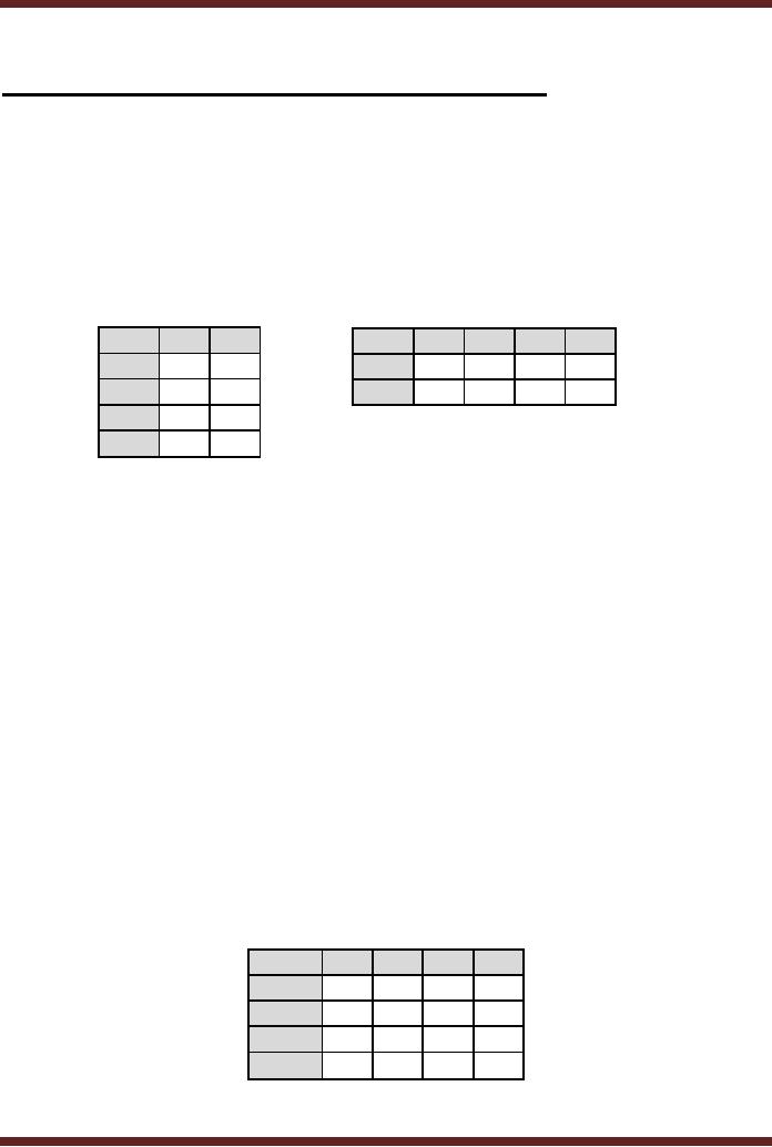
The
3-variable Karnaugh
Map
AB\C
0
1
A\BC
00
01
11
10
00
0
1
0
0
1
3
2
01
2
3
1
4
5
7
6
11
6
7
10
4
5
Figure
10.1
Column
and Row based 3-variable
Karnaugh Maps
·
A 3-variable
K-Map has an array of 8
cells. The 8 cells can be
arranged in 2 columns and
4
rows
representing the column form
of the Karnaugh Map.
·
Alternately,
the 8 cells can be organized
in 2 rows and 4 columns
representing the row
form of
the Karnaugh map.
·
Any of the
two forms of the Karnaugh
Map can be used to simplify
Boolean expressions.
The
simplified expressions using
either of the two K-maps
are identical.
·
Considering
first the column based
3-variable Karnuagh map. The
binary values 00, 01,
11
and 10 in
the left most column of
the K-map represent the
binary values of variables A
and
B. The
binary values 0 and 1 in the
top row of the K-map
represent the binary values
of
variable
C.
·
The
3-variable K-Map based on
the row representation is
considered next. The
binary
values 0
and 1 in the left most
column of the K-map
represent the binary values
of variable
A. The
binary values 00, 01, 11
and 10 in the top row of
the K-map represent the
binary
values of
variables B and C
·
The
numbers in the cells
represent the Minterms or
Maxterms of an expression that is
to
be represented
using the K-map. The
cell marked 0 for example,
represents the minterm
0
or the
maxterm 0 having binary
value of variables A, B and C
equal to 000. Similarly
cell
marked 5
represents the minterm 5 or
the maxterm 5 having binary
values of variables A,
B and C
equal to 101.
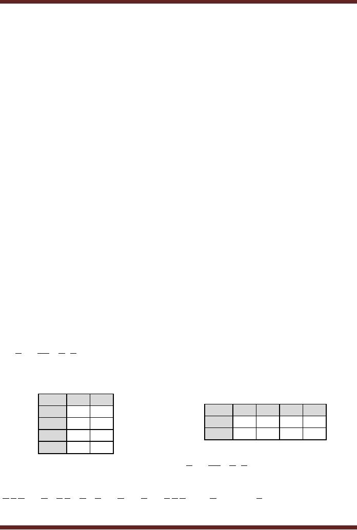
The
4-variable Karnaugh
Map
AB\CD
00
01
11
10
00
0
1
3
2
01
4
5
7
6
11
12
13
15
14
10
8
9
11
10
Figure
10.2
4-variable
Karnaugh Map
89
CS302 -
Digital Logic & Design
·
A 4-variable
K-Map has an array of 16
cells
·
The
numbers in the cells
represent the Minterms and
Maxterms of an expression that is
to
be represented
using the K-map.
·
The
4-variable K-Map has a
square format with four
rows and four columns of
cells.
·
The
binary values 00, 01, 11
and 10 in the left most
column of the K-map
represent the
binary
values of variables A and B.
The binary values 00,
01, 11 and 10 in the top
row of
the
K-map represents the binary
values of variables C and
D
·
The 16
cells marked with numbers 0
to 15 represent the cells 0 to 15
corresponding to the
minterms 0 to 15
or the maxterms 0 to 15 in a 4 variable
Boolean expression.
·
The
cell marked 6 for example,
represents the minterm 6 or
the maxterm 6 having
binary
value of
variables A, B, C and D equal to
0110. Similarly cell marked
13 represents the
minterm 13 or
the maxterm 13 having binary
values of variables A, B, C and D
equal to
1101.
Grouping
and Adjacent
Cells
Karnaugh Map
Array is considered to be wrapped
around were all sides
are adjacent
to each
other. Groups of 2, 4, 8, 16, 32
etc. adjacent cells are
formed. Adjacent cells can
be
· row
wise
· column
wise
· four
corner cells
· row-column
groups of 4, 8, 16, 32
etc
Groups
are formed on the basis of
1s (Minterms) or 0s (maxterms). A group
is selected
to have
maximum number of cells of
Minterms or Maxterms, keeping in
view that the size
of
the
group should be a power of 2.
The idea is to form minimal
number of largest groups
that
uniquely
cover all the cells,
thereby ensuring that all
minterms or maxterms are
included.
Mapping a
standard SOP
Expression
The
first step in simplification of
Boolean expressions is to map
the expressions to
the
Karnaugh
maps. For a Standard SOP
expression, a 1 is placed in the
cell corresponding to
the
product
term (Minterm) present in
the expression. The cells
that are not filled
with 1s have 0s.
The
Standard SOP expression
having a Domain of
three variables
ABC + ABC + ABC is mapped to a
3-Variable Karnaugh Map. The
product terms or the
Minterms
are 2, 4 and 6. The
expression is mapped on a K-Map by
placing a 1 at Minterm
cells 2, 4
and 6 and placing 0 at
remaining cells.
AB\C
0
1
A\BC
00
01
11
10
00
0
0
0
0
0
0
1
01
1
0
1
1
0
0
1
11
1
0
10
1
0
Mapping
the expression ABC + ABC + ABC to a 3-variable
K-Map
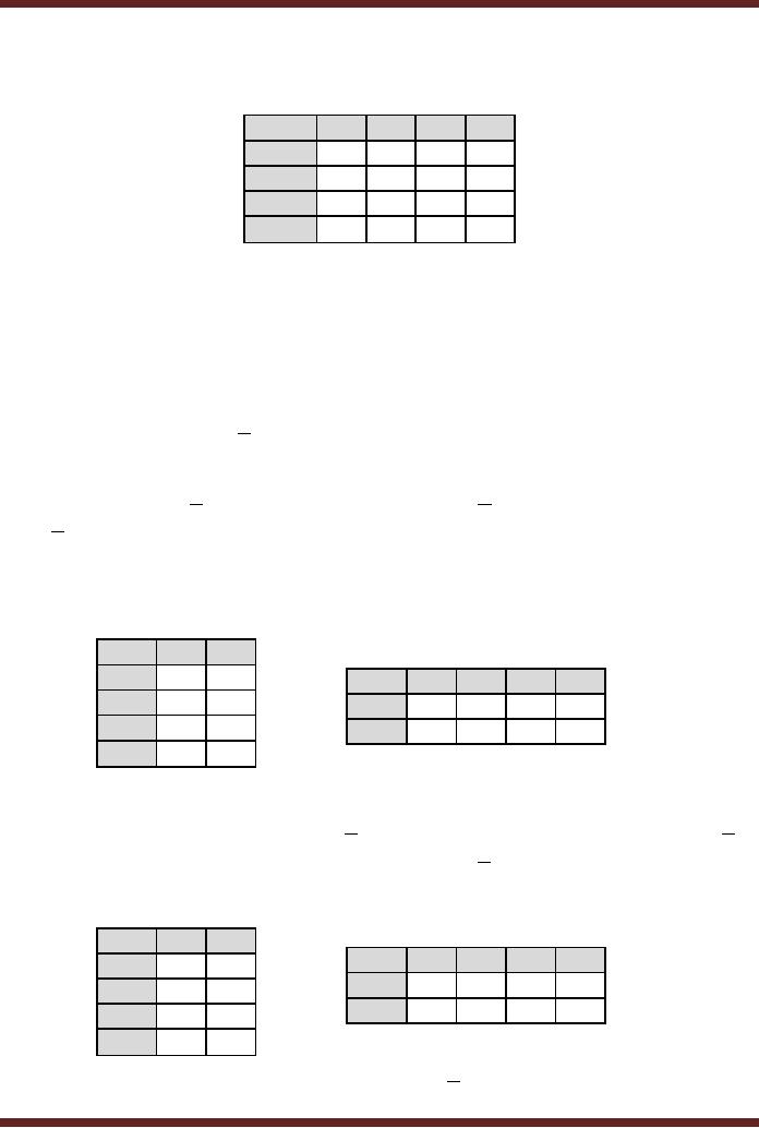
Figure
10.3
The
Standard
SOP
expression
having
a
domain
of four
variables
A.B.C.D + A.B.C.D + A.B.C.D + A.B.C.D + A.B.C.D + A.B.C.D + A.B.C.D is mapped to a
4-
variable
Karnaugh Map. The product
terms or the Minterms are 1,
4, 5, 6, 8, 13 and 14.
The
90
CS302 -
Digital Logic & Design
expression is
mapped on a K-Map by placing a 1 at
Minterm cells 1, 4, 5, 6, 8, 13 and 14
and
placing 0 at
remaining cells.
AB\CD
00
01
11
10
00
0
1
0
0
01
1
1
0
1
11
0
1
0
1
10
1
0
0
0
Figure
10.4
Mapping
the 7 term SOP expression to
a 4-variable K-Map
Mapping a
non-standard SOP
Expression
In many
practical cases, SOP
expressions are not in a
standard format. To map
them
to K-maps
they have to be either
converted into Standard SOP
expressions or they can
be
directly
mapped.
Example
1
The
expression A
+
BC is a non-standard
SOP expression having a
domain of 3
variables. If
the expression is converted
into a standard SOP
expression then there will
be four
product
terms having the variable
A . Similarly, there
would be two product terms
having the
variable
combination BC
. Two of
the product terms ABC are identical. The
expression
A + BC can be directly
mapped to a K-map without
first converting the
expression to the
standard
form.
The
term A is mapped first. A
`1' is marked in cells where
the variable A is
present.
AB\C
0
1
00
A\BC
00
01
11
10
01
0
11
1
1
1
1
1
1
1
10
1
1
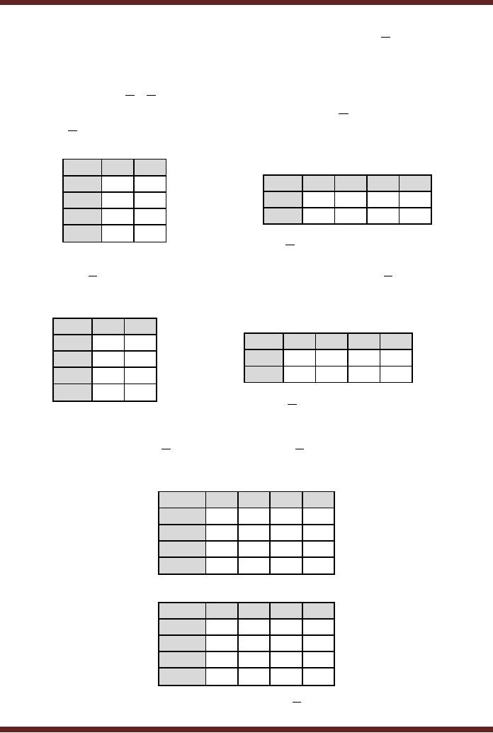
Figure
10.5
Mapping
the expression A to a 3-variable
K-Map
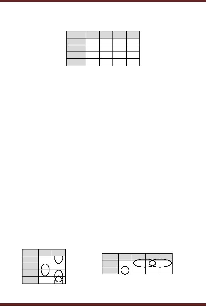
Consider
the mapping of the term
BC . A `1' is marked
in cells where the variable
BC is
present.
The cells are marked
with 1. One of
the cells ABC has already been
marked when
mapping
the terms containing
variable A
.
AB\C
0
1
A\BC
00
01
11
10
00
0
0
0
0
0
0
1
01
0
1
1
1
1
1
1
11
1
1
10
1
1
Mapping
the expression BC to a
3-variable K-Map
Figure
10.6
91
CS302 -
Digital Logic & Design
The
K-map shows that if the
non-standard SOP expression A + BC is converted into
a
standard
SOP expression it would have
five product terms as
represented by the K-map
cells.
Example
2
The
expression A
+
C is a non-Standard
SOP expression having a
domain of 3
variables. It is
mapped directly to a 3-variable
K-map. The term A is mapped first by
marking
cells
having A
with
`1'.
AB\C
0
1
A\BC
00
01
11
10
00
1
1
0
1
1
1
1
01
1
1
1
0
0
0
0
11
0
0
10
0
0
Mapping
the expression A to a
3-variable K-Map
Figure
10.7
The
term C
is mapped
next. A `1' is marked in
cells where the term
C is present.
AB\C
0
1
A\BC
00
01
11
10
00
1
1
0
1
1
1
1
01
1
1
1
0
0
1
1
11
0
1
10
0
1
Mapping
the expression C to a
3-variable K-Map
Figure
10.8
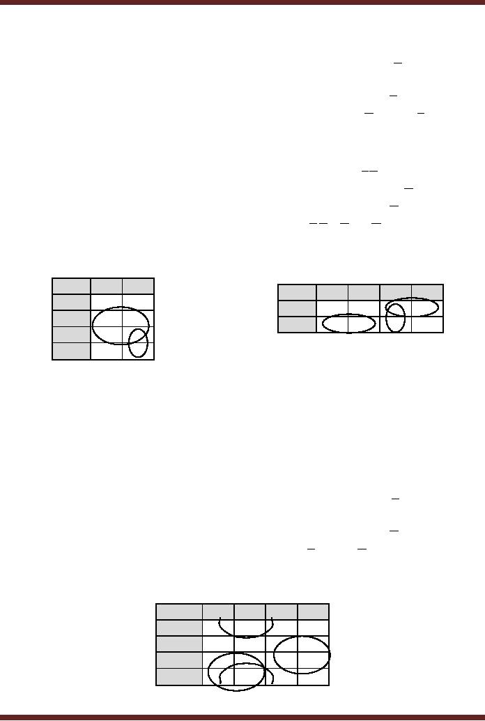
Mapping of
non-standard SOP expressions
having a domain of 4 variables is
similar.
Consider
the expression D + AC + BC . The terms
D , AC and BC are mapped one
after the
other by
marking cells with `1's
where these terms are
present.
AB\CD
00
01
11
10
00
0
1
1
0
01
0
1
1
0
11
0
1
1
0
10
0
1
1
0
Figure
10.9a Mapping the expression
D to a 4-variable
K-Map
AB\CD
00
01
11
10
00
0
1
1
0
01
0
1
1
0
11
1
0
1
1
10
1
0
1
1
Figure
10.9b Mapping the expression
AC to a 4-variable
K-Map
92
CS302 -
Digital Logic & Design
AB\CD
00
01
11
10
00
0
1
1
0
01
0
1
1
1
11
1
1
1
1
10
1
1
1
0
Figure
10.9c Mapping the expression
BC to a 4-variable
K-Map
Simplification of
SOP expressions using the
Karnaugh Map
SOP
expressions can be very
easily simplified using the
K-Map method. In the
first
step of
the simplification process,
the SOP expression is mapped
on the K-map. In the
next
step,
groups of 1s are formed
starting with the largest
group of 1s. The group
should be of size
2, 4, 8, 16 etc.
having adjacent 1s. Multiple
(unique) groups of 1s are
formed. All the
groups
formed
can either be separate
groups or they could share
common 1s each having at
least a
single 1
that is not common to any
other group. A single 1 that
is not adjacent to any other
1 is
considered as a
group having only a single
cell.
In the
next step minimal product
terms are determined. Each
group, including a
group
having a
single cell, represents a
product term having
variables that occur in only
one form
either
complemented or un-complemented.
A 3-variable
K-map yields
· A product
term of three variables for
a group of 1 cell
· A product
term of two variables for a
group of 2 cell
· A product
term of one variable for a
group of 4 cell
· A group of
8 cells yields a value of 1
for the expression.
A 4-variable
K-map yields
· A product
term of four variables for a
group of 1 cell
· A product
term of three variables for
a group of 2 cell
· A product
term of two variables for a
group of 4 cell
· A product
term of one variable for a
group of 8 cell
· A group of
16 cells yields a value of 1
for the expression.
Example 1 &
2
0
1
AB\C
00
01
11
10
A\BC
00
0
1
0
0
1
1
1
01
1
0
1
1
0
0
0
11
1
1
10
0
1
Figure
10.10 Simplification of SOP
expression using a 3-variable
K-Map
93
CS302 -
Digital Logic & Design
An SOP
expression having 5 minterms is
mapped to a 3-variable column
based K-
map.
Three groups of two cells
each are formed.
· The
first group of 1s comprising of
cells 2 and 6 forms the
product term BC
· The
second group of 1s comprising of
cells 5 and 7 forms the
product term AC
·
The
third group of 1s comprising of
cells 1 and 5 forms the
product term BC
The
five term SOP expression
simplifies to a 3 term SOP
expression B.C + A.C + B.C
An SOP
expression having 4 minterms is
mapped to a 3-variable row
based K-map.
Two
groups of 2 cells each and a
third group of single cell
are formed.
· The
single cell group comprising
of cell 4 forms the product
term ABC
·
The
second group of 1s comprising of
cells 1 and 3 forms the
product term AC
· The
third group of 1s comprising of
cells 2 and 3 forms the
product term AB
The
four term SOP simplifies to
a 3 term SOP expression A.B.C + A.C + A.B
Example 3 &
4
0
1
AB\C
A\BC
00
01
11
10
0
0
00
0
0
0
1
1
1
1
01
1
1
1
1
0
1
1
11
0
1
10
Figure
10.11 Simplification of SOP
expression using a 3-variable
K-Map
An SOP
expression having 5 minterms is
mapped to a 3-variable column
based K-
map.
One group of 4 cells and
another group of 2 cell are
formed.
· The
first group of 1s comprising of
cells 2, 3, 6 and 7 forms
the product term B
· The
second group of 1s comprising of
cells 5 and 7 forms the
product term AC
The
five term SOP simplifies to
a 2 term SOP expression B + AC
An SOP
expression having 5 minterms is
mapped to a 3-variable row
based K-map.
Three
groups of 2 cells each are
formed.
· The
first group of 1s comprising of
cell 4 and 5 forms the
product term A.B
· The
second group of 1s comprising of
cells 3 and 7 forms the
product term B.C
·
The
third group of 1s comprising of
cells 2 and 3 forms the
product term A.B
The
five term SOP simplifies to
a 3 term SOP expression A.B + B.C + A.B
Example
5
AB\CD
00
01
11
10
00
0
1
1
0
1
01
0
0
1
1
11
1
1
1
10
1
1
1
0
Figure
10.12 Simplification of SOP
expression using a 4-variable
K-Map
94
CS302 -
Digital Logic & Design
An SOP
expression having 11 minterms is
mapped to a 4-variable based
K-map.
Three
groups of 4 cells each are
formed.
· The
first group of 1s comprising of
cells 8, 9, 12 and 13 forms
the product term A.C
·
The
second group of 1s comprising of
cells 1, 3, 9 and 11 forms
the product term B.D
·
The
third group of 1s comprising of
cells 6, 7, 14 and 15 forms
the product term B.C
The
eleven term SOP expression
has simplified to a 3 term
expression A.C + B.D + B.C
Example
6
An SOP
expression having 8 minterms is
mapped to a 4-variable based
K-map. One
group of
two cells and two
groups of four cells are
formed.
· The
first group of 1s comprising of
cells 8 and 12 forms the
product term A.C.D
· The
second group of 1s comprising of
cells 3, 7, 11 and 15 forms
the product term C.D
· The
third group of 1s comprising of
cells 6, 7, 14 and 15 forms
the product term B.C
The
eight term SOP expression
has simplified to a 3 term
expression A.C.D + C.D + B.C
11
AB\CD
00
01
10
00
0
0
1
0
01
0
0
1
1
1
11
0
1
1
10
1
0
1
0
Figure
10.13 Simplification of SOP
expression using a 4-variable
K-Map
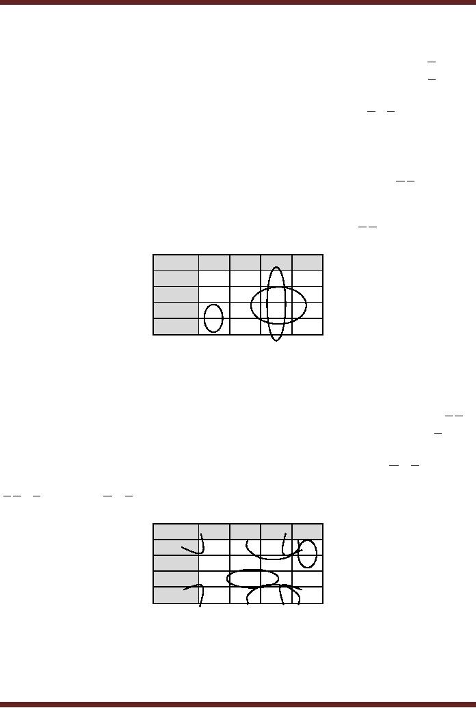
Example
7
An SOP
expression having 9 minterms is
mapped to a 4-variable based
K-map. Two
group of
two cells and two
groups of four cells are
formed.
· The
first group of 1s comprising of
corner cells 0, 2, 8 and 10
forms the product term
B.D
·
The
second group of 1s comprising of
cells 2, 3, 10 and 11 forms
the product term B.C
·
The
third group of 1s comprising of
cells 13 and 15 forms the
product term A.B.D
· The
fourth group of 1s comprising of
cells 2 and 6 forms the
product term A.C.D
The
nine term SOP
expression has
simplified to a 4 term
SOP expression
B.D + B.C + A.B.D + A.C.D
AB\CD
00
01
11
10
1
00
1
0
1
01
0
0
0
1
11
1
1
0
10
1
0
1
1
Figure
10.14 Simplification of SOP
expression using a 4-variable
K-Map
Mapping
Directly from Function
Table
Practically,
when a digital circuit is to be
implemented to perform some
operation, its
function is
first defined using a
function table. The
information in the function
table is directly
95
CS302 -
Digital Logic & Design
mapped to a
K-map of appropriate variables
which is then simplified.
The simplified
expression
obtained
from the K-map is directly
implemented using logic
Gates.
Consider a
logical circuit that accepts
4-bit binary numbers
representing decimal
numbers 0 to
15. The circuit checks
the four bit binary
equivalent of the decimal
number. If the
number is
odd and it is a prime number
the function outputs a one.
Before designing the
logic
circuit a
function table is implemented
with all the input
output combinations. The
function table
for
the odd prime number
checker is shown. Table 10.1
The output is a 1 for inputs
1, 3, 5, 7,
11 and
13.
Input
Output
Input
Output
A
B
C
D
F
A
B
C
D
F
0
0
0
0
0
1
0
0
0
0
0
0
0
1
1
1
0
0
1
0
0
0
1
0
0
1
0
1
0
0
0
0
1
1
1
1
0
1
1
1
0
1
0
0
0
1
1
0
0
0
0
1
0
1
1
1
1
0
1
1
0
1
1
0
0
1
1
1
0
0
0
1
1
1
1
1
1
1
1
0
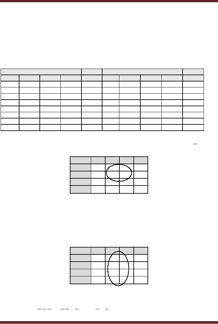
Table
10.1
Function
Table for Odd-Prime Checker
Circuit
The 4
variable Function Table,
Table 10.1 can be directly
mapped to a 4 variable K-
map by
marking the K-map cells
with 1s corresponding to the
minterms marked as 1s in
the
function
table. Figure 10.14.
Simplifying the expression
using the K-map results
in
A.D + B.C.D + B.C.D . The expression
can be directly implemented
using logic gates.
01
AB\CD
00
11
10
00
0
1
1
0
1
01
0
1
0
0
11
0
1
0
10
0
0
1
0
Figure
10.14 Simplification of expression
using a 4-variable
K-Map
Don't
care Conditions
Function
Tables represent the
function by listing all the
possible inputs and marking
the
corresponding
outputs with 1s and 0s.
Thus a circuit having four
inputs can be described by
a
4-variable
function table having 16
possible input combinations.
For each of the 16
possible
input
conditions the corresponding
output bits are marked as 1s
and 0s depending upon
the
minterms or
maxterms. It is however, possible
that out of the 16 possible
input combinations,
three
input combinations never
occur. Since these three
input combinations never
occur so
should
their corresponding outputs be
marked as 0s or 1s? Since
these inputs never
care
therefore we
don't need to worry about
the output of these input
states. They are considered
to
be don't
care conditions.
Don't
care conditions are marked
as x in the output column of
the function table
corresponding to
the don't care conditions.
When the function table is
mapped to the
96
CS302 -
Digital Logic & Design
corresponding
K-map, the don't care
conditions are marked as x.
However during the
grouping
process
for simplification of the
SOP expression the x outputs
can be considered as 0 or 1. By
assigning a 0 or
1 to the cells marked with
x, the final expression can
be significantly
simplified.
Reconsider
the last example of the
Odd-Prime Number checker
circuit. Assuming
that
only
the first ten input (0 to 9)
states can occur and
the last 6 inputs never
occur. The function
table
for the conditions that
never occur is shown. Table
10.2
Input
Output
Input
Output
A
B
C
D
F
A
B
C
D
F
0
0
0
0
0
1
0
0
0
0
0
0
0
1
1
1
0
0
1
0
0
0
1
0
0
1
0
1
0
x
0
0
1
1
1
1
0
1
1
x
0
1
0
0
0
1
1
0
0
x
0
1
0
1
1
1
1
0
1
x
0
1
1
0
0
1
1
1
0
x
0
1
1
1
1
1
1
1
1
x
The
function table can be
directly mapped to a 4 variable
K-map. Figure 10.15. The
cells
marked
with x are considered to be
0s. Thus the function
expression is simplified to A.D
AB\CD
00
01
11
10
1
00
0
1
0
01
0
1
1
0
11
x
x
x
x
10
0
0
x
x
Figure
10.15 Simplification of expression
with Don't care
states
If the
Odd-Parity Checker Circuit
checks for numbers between 0
and 8, and states 9
to
15 never
occur then the Boolean
expression representing the
function reduces to a
single
literal
D Figure 10.16.
The cells 9, 10, 11,
13, 14 and 15 marked as `x'
as they represent the
don't
care states are considered
as 1's to form a group of 8
cells. Remaining cells
marked with
`x'
are considered as 0's and
are not involved in
grouping.
01
AB\CD
00
11
10
00
0
1
1
0
01
0
1
1
0
11
x
x
x
x
10
0
x
x
x
Figure
10.16 Simplification of expression
with Don't care
states
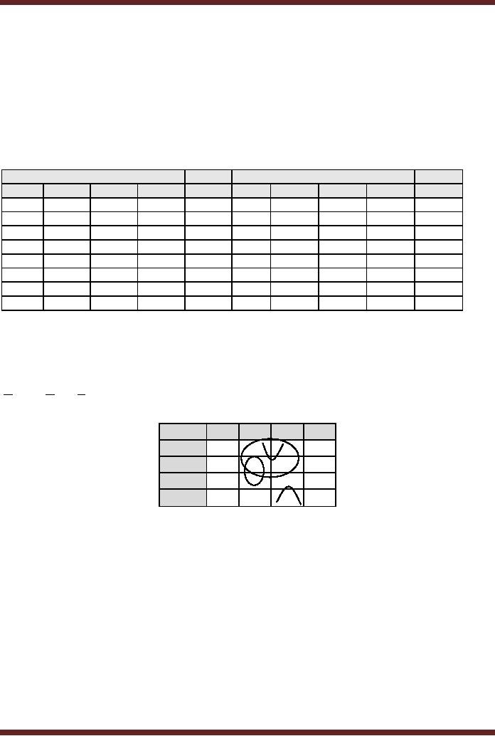
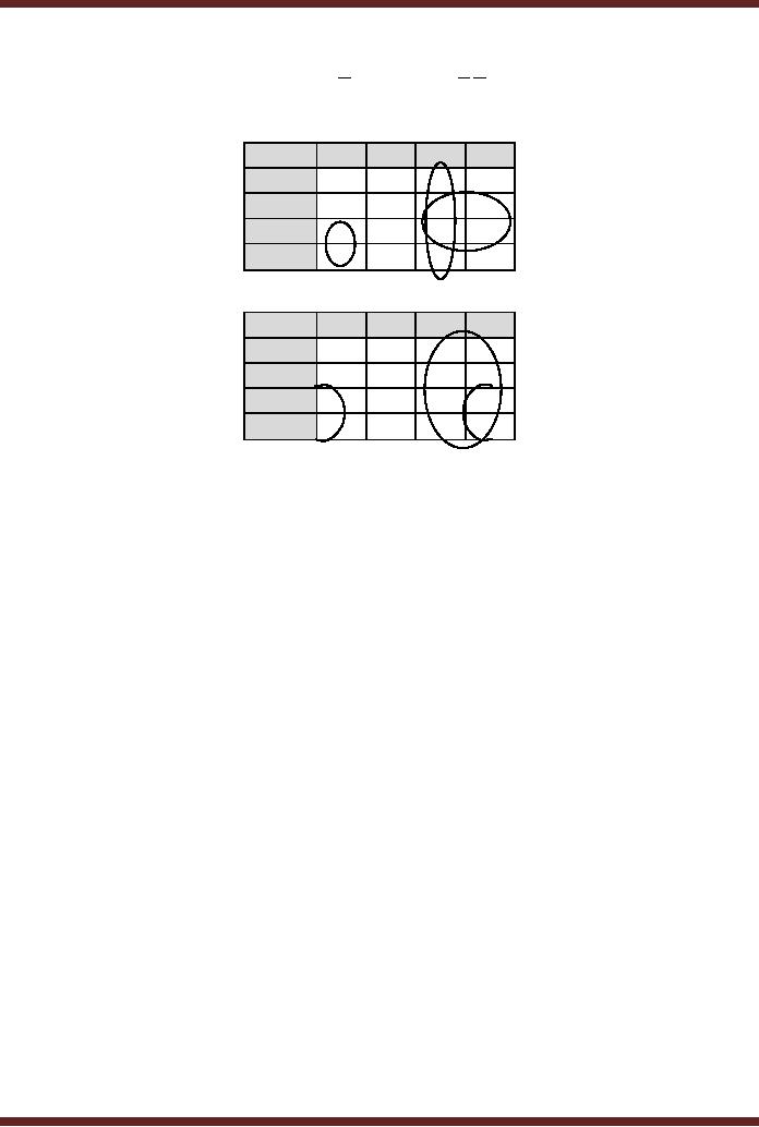
Consider
the K-map considered earlier
in Example 6. Figure 10.13.
Assume that the
input
conditions A.B.C.D , A.B.C.D and A.B.C.D never occur so
they are marked as x in the
K-
97
CS302 -
Digital Logic & Design
map
cells corresponding to the
minterms that never occur.
Redefining the groups using
x as 0
or 1 results in
a simpler expression C + A.D instead of A.B.C + C.D + B.C . Figure
10.17.
11
AB\CD
00
01
10
x
00
0
1
x
01
0
0
1
1
1
11
0
1
1
10
1
0
1
x
11
AB\CD
00
01
10
00
0
x
1
x
01
0
0
1
1
11
1
0
1
1
10
1
0
1
x
Figure
10.17
Simplified
expression by incorporating the
don't care states
98
Table of Contents:
- AN OVERVIEW & NUMBER SYSTEMS
- Binary to Decimal to Binary conversion, Binary Arithmetic, 1s & 2s complement
- Range of Numbers and Overflow, Floating-Point, Hexadecimal Numbers
- Octal Numbers, Octal to Binary Decimal to Octal Conversion
- LOGIC GATES: AND Gate, OR Gate, NOT Gate, NAND Gate
- AND OR NAND XOR XNOR Gate Implementation and Applications
- DC Supply Voltage, TTL Logic Levels, Noise Margin, Power Dissipation
- Boolean Addition, Multiplication, Commutative Law, Associative Law, Distributive Law, Demorgans Theorems
- Simplification of Boolean Expression, Standard POS form, Minterms and Maxterms
- KARNAUGH MAP, Mapping a non-standard SOP Expression
- Converting between POS and SOP using the K-map
- COMPARATOR: Quine-McCluskey Simplification Method
- ODD-PRIME NUMBER DETECTOR, Combinational Circuit Implementation
- IMPLEMENTATION OF AN ODD-PARITY GENERATOR CIRCUIT
- BCD ADDER: 2-digit BCD Adder, A 4-bit Adder Subtracter Unit
- 16-BIT ALU, MSI 4-bit Comparator, Decoders
- BCD to 7-Segment Decoder, Decimal-to-BCD Encoder
- 2-INPUT 4-BIT MULTIPLEXER, 8, 16-Input Multiplexer, Logic Function Generator
- Applications of Demultiplexer, PROM, PLA, PAL, GAL
- OLMC Combinational Mode, Tri-State Buffers, The GAL16V8, Introduction to ABEL
- OLMC for GAL16V8, Tri-state Buffer and OLMC output pin
- Implementation of Quad MUX, Latches and Flip-Flops
- APPLICATION OF S-R LATCH, Edge-Triggered D Flip-Flop, J-K Flip-flop
- Data Storage using D-flip-flop, Synchronizing Asynchronous inputs using D flip-flop
- Dual Positive-Edge triggered D flip-flop, J-K flip-flop, Master-Slave Flip-Flops
- THE 555 TIMER: Race Conditions, Asynchronous, Ripple Counters
- Down Counter with truncated sequence, 4-bit Synchronous Decade Counter
- Mod-n Synchronous Counter, Cascading Counters, Up-Down Counter
- Integrated Circuit Up Down Decade Counter Design and Applications
- DIGITAL CLOCK: Clocked Synchronous State Machines
- NEXT-STATE TABLE: Flip-flop Transition Table, Karnaugh Maps
- D FLIP-FLOP BASED IMPLEMENTATION
- Moore Machine State Diagram, Mealy Machine State Diagram, Karnaugh Maps
- SHIFT REGISTERS: Serial In/Shift Left,Right/Serial Out Operation
- APPLICATIONS OF SHIFT REGISTERS: Serial-to-Parallel Converter
- Elevator Control System: Elevator State Diagram, State Table, Input and Output Signals, Input Latches
- Traffic Signal Control System: Switching of Traffic Lights, Inputs and Outputs, State Machine
- Traffic Signal Control System: EQUATION DEFINITION
- Memory Organization, Capacity, Density, Signals and Basic Operations, Read, Write, Address, data Signals
- Memory Read, Write Cycle, Synchronous Burst SRAM, Dynamic RAM
- Burst, Distributed Refresh, Types of DRAMs, ROM Read-Only Memory, Mask ROM
- First In-First Out (FIFO) Memory
- LAST IN-FIRST OUT (LIFO) MEMORY
- THE LOGIC BLOCK: Analogue to Digital Conversion, Logic Element, Look-Up Table
- SUCCESSIVE APPROXIMATION ANALOGUE TO DIGITAL CONVERTER