 |

Database
Management System
(CS403)
VU
Lecture No.
10
Reading
Material
"Database
Systems Principles, Design and
Implementation"
Page: 155
160
written
by Catherine Ricardo, Maxwell
Macmillan.
Hoffer
Page: 103
111
Overview of
Lecture
o Cardinality
Types
o Roles in
ER Data Model
o Expression
of Relationship in ER Data Model
o Dependency
o Existence
Dependency
o Referential
Dependency
o Enhancements
in the ER-Data Model
o Subtype
and Supertype entities
Recalling
from the previous lecture we
can say that that
cardinality is just an
expression
which
tells us about the number of
instances of one entity which can be present in
the
second
relation. Maximum cardinality
tells us that how many
instance of an entity can be
placed in
the second relation at most.
Now we move onto discuss
that what the
minimum
cardinality
is.
Minimum
Cardinality:
As the
name suggests that the
minimum cardinality is the
inverse of the
maximum
cardinality
so we can say that the minimum
cardinality show us that how
many instance
of one
entity can be placed in another relation
at least. In simple words it can be said
that
the
minimum cardinality tells
that whether the link
between two relations is
optional or
compulsory.
It is very important to determine
the minimum cardinality when
designing a
database
because it defines the way a
database system will be
implemented.
91
Database
Management System
(CS403)
VU
STD
BOOK
One to
Many (optional)
EMP
PROJ
Many to
One (Mandatory)
STD
COURSE
Many to Many
(optional)
STD
HOBBY
Many to
One (optional)
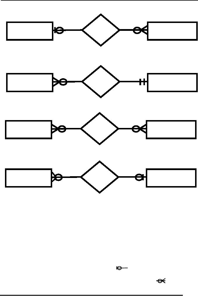
Fig 1:
Different Cardinalities
In the
figure-1 we have one to many
cardinality between the
entities. Maximum
cardinalities
are shown with the
modifier that appears on the
link and is adjacent to
the
entity
rectangle. The other
modifier which is next to
the maximum cardinality
modifier
tells
the minimum cardinality. The
minimum cardinality modifier
lies at more distance
from
the entity as compared to the
maximum cardinality
modifier.
Determination
of the cardinalities is done by
interviewing the users of
the system and by
the
analysis of the
organization.
The
cardinality shown in First Part of
the Figure-1 is shown using
a relationship between
a student
and book; this can be a library scenario
where students are borrowing
books
adjacent
to the student entity
from
the library. We can see in
the diagram the
shape
it shows
that the minimum cardinality
for the student relationship
is zero and maximum
cardinality
is one. Where as on the
other side of the diagram
the shape
adjacent
to
92

Database
Management System
(CS403)
VU
the
book entity show that at
most there can be many instances of
the book associated
with
a single
instance of student entity, and
that there can be at-least no
instance associated
with
the student entity. In
general library scenario we can say
that one student can
borrow
at least no and at
most many books. Hence
the minimum and maximum
cardinality is
shown.
In the
second part of the Figure-1
we see a relationship between
the Employee and
project
entities, the relationship
describes one to many association between
the project
and the
employees, It shows that
there can be one project having a
number of employees,
but
for the existence of one
employee at one project is necessary. So
the minimum and
maximum
cardinality on the project
side of the relationship is
one, and employees
associated
with each project can be
many at most and none
at-least.
Third
part of the Figure-1 shows
the association between the
student and the course
entities.
Here we can see that the
relationship between the
student and the course is
zero
at least and
many at most on both the
sides of the relationship.
The minimum
cardinality
with
zero minimum is also called
the optional cardinality. It also
shows that one
student
can have
registered more that one subjects and one
subject can also be taken by
many
students.
Also it is not necessary for
a student to get registered one
subject.
In the
fourth part of the Figure-1
we can see the one to many
cardinality between
the
student
and hobby entities the
cardinality descriptors show that a
student may have no
or
at most
one hobby, but it is worthwhile to
notice that the cardinality
of the hobby with
the
student
in many but optional, now we
can say that one hobby can be
associated to nay
student
but there is a chance that no
hobby is associated to one student at a
certain time.
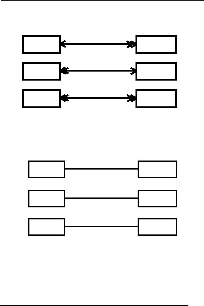
Other
Notations:
The
notation mentioned above is known as
crow's foot notation for
the expression of ER-
Diagrams,
there can be other notation as
well which can be used for
creating ER-
Diagrams;
one of these notations is shown in
the Figure-2. We can see
that the one to
many
cardinality shown in the
first part of the diagram is
expresses with single
and
double
arrows. The Single arrow in
this case shows the one and
double arrow show
the
many
cardinality.
93
Database
Management System
(CS403)
VU
STD
BOOK
HOBBY
STD
PROJ
EMP
Fig. 2:
Arrow-head notation
So the
First part of the figure-2
show One to many
cardinality, second part of
the Figure
shows
many to one and the third
part of the cardinality
shows many to many
cardinality
between
the entities
involved.
M
1
STD
BOOK
M
1
HOBBY
STD
M
M
PROJ
EMP
Fig. 3:
Alphabetical notation
The above
Figure shows another
notation for creating
ER-Diagrams which show that
to
show
the one cardinality we have
used 1 and for many
cardinality M or N is used.
94
Database
Management System
(CS403)
VU
1
1
CHAIR
DEPT
1
STD
BOOK
PROJ
EMP
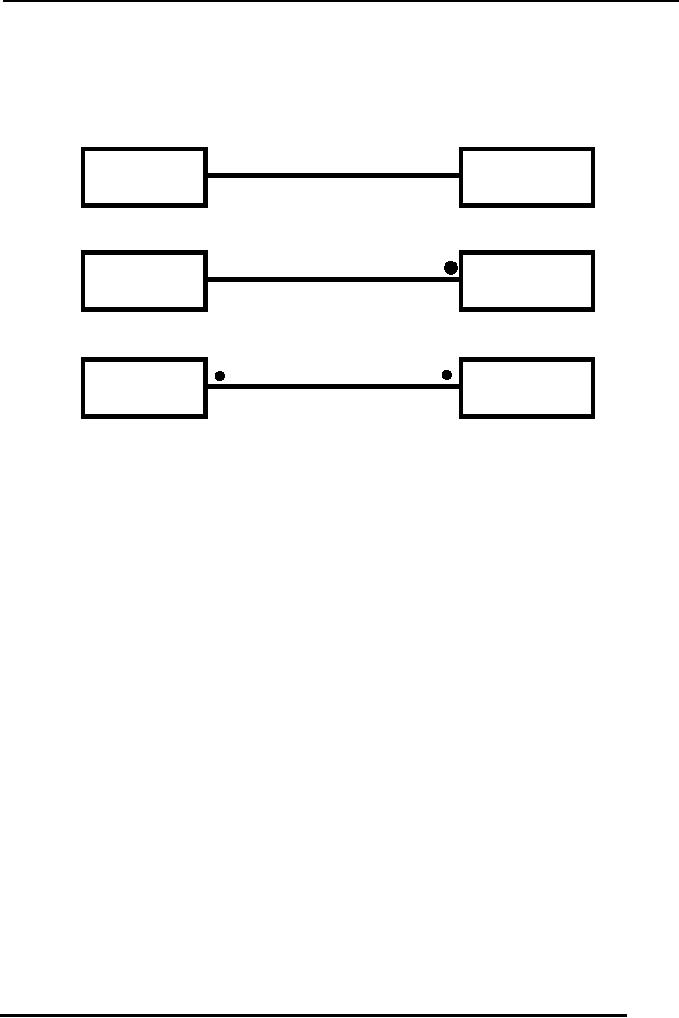
Fig. 4:
Dot-based notation
Notations
shown in the Figure-4 above as also
used for creating
ER-Diagrams where 1 is
used
for showing the single
cardinality and the black
filled Dot is used for
showing many
cardinality.
Roles in
Relationships
The
way an entity is involved in a
relationship is called the
role of the entity in
the
relationship.
These details provide more semantics of
the database. The role is
generally
clear
from the relationship, but
in some cases it is necessary to
mention the role
explicitly.
Two
situations to mention the
role explicitly
Recursive
Relationship:
This is
the situation when any
attribute of one entity is associated
with another
attribute
of the
same entity. Such a link
initiates from one entity and
terminates on the same
entity.
95
Database
Management System
(CS403)
VU
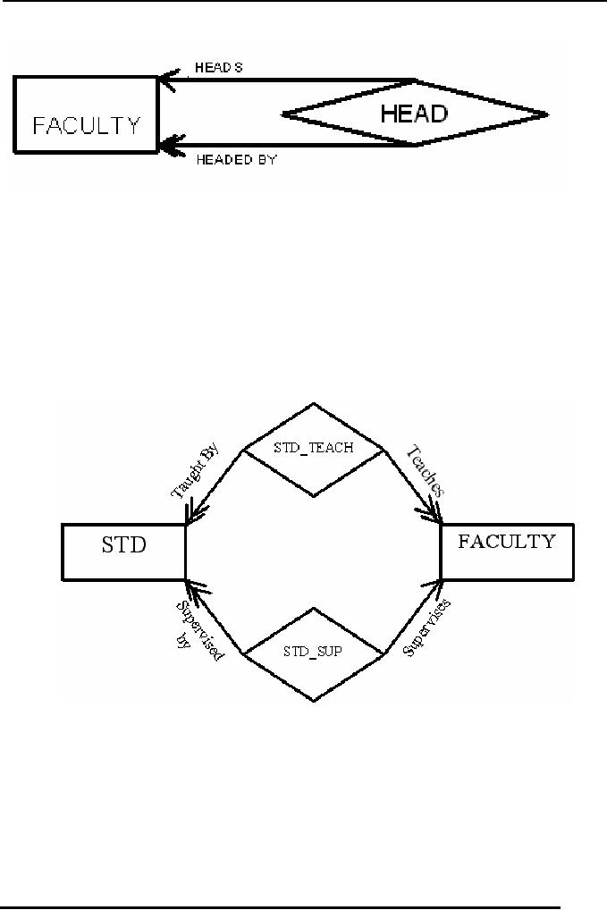
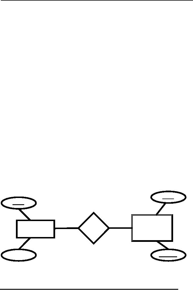
Fig-5:
Roles in a unary
relationship
Figure-5
above shows the recursive
relationship which tells
that in the faculty of a
certain
institute
we can have one faculty member
from among the same
faculty as the head of
the
faculty.
Now the role mentioned on
the relationship tell that
many Faculty instance
are
headed by
one of the entity instance
from the same faculty
relation.
Multiple
Relationships:
This is
the second situation which
needs the role to be
mentioned on the relationship
link
when
there is more than one
relationship.
Fig. 6:
Multiple relationships
As an
example we can have a relationship of
Faculty members and students as
one
faculty
member may teach a number of
students and at the same
time one student may
have
been taught by a number of
faculty members. This is one
side of the picture.
Now
on the
other side we can say that a
faculty member may be
supervising a number of
students
for their final projects. It
shows two types of associations
between the faculty
and the
students. So in this type of
situation it is necessary to mention
the role of the
entities
involved in the
relationship.
96
Database
Management System
(CS403)
VU
Dependencies
Dependency
is a type of constraint, for
example once we define the
cardinality or
relationship
among two entities it also is a
constraint or check that
tells that
cardinality
should be
followed while populating
data in relations. Similarly
the dependency is a
constraint.
There are a number of
dependency types which are
expressed below:
The
Existence dependency:
This is
the type of dependency which
exists when one entity
instance needs instance
of
another
entity for its existence. As
we have seen earlier in case
of employee of and
organization
and the projects associated
with the employees there we
see that employees
are
dependent on projects, it means that if
no project is assigned to an employee it
can not
exist. In
other words we can say that
at a certain time an employee
must be working on at
least one
project.
Identifier
Dependency:
It means
that the dependent entity
incase of existence dependency
does not have its
own
identifier
and any external identifier is
used to pick data for
that entity. And to define
a
key in
this entity the key of
the parent entity is to be
used in the key for
this entity may be
used as
composite keys.
Referential
Dependency:
This is
the situation when the
dependent entity has it own
key for unique
identification
but
the key used to show
the reference with the
parent entity is shown with
the help of an
attribute
of the parent entity. Means
to show the link of the
parent entity with this
entity
there
will be an attribute and a record in this
entity will not exist
without having a
record
in the
parent entity. Despite of having
its own identifier
attribute.
This
type of identifier or attribute in
the weak entity is known as
foreign key.
bkId
bkId
BOOK
BOOK
COPY
bkTitle
CopyId
Fig-7
97
Database
Management System
(CS403)
VU
In the
Figure-7 above the relation
shown is expression the
existence dependency where
it
is
necessary for a book
instance to exist if there
exist the copies of the
book with the
same
bkId.
Enhancements
in E-R Data Model:
The
topics that we have
discussed so for constitute
the basics of ER-Model. The
model is
further
extended and strengthened with
addition of some new concepts and
modeling
constructs,
which are discussed
below
Super-type
and Subtypes
These are
also relationships existing between
entities, also referred to as generalized
and
specialized
respectively let us examine
the figure below to grasp
the idea of
super-type
and
subtype.
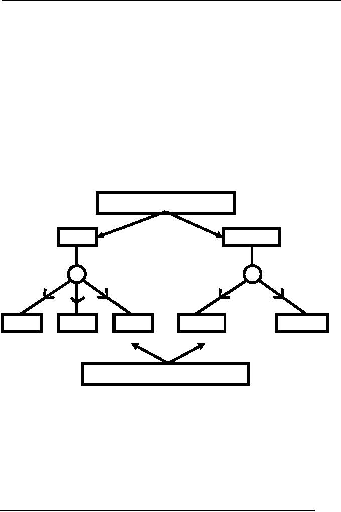
General
Entity Types
ST
PERSON
ST1
ST2
ST3
STD
FAC
Specialized
Entity Types
Fig-8
(Super-types and Subtypes)
In the
Figure:8 show above there
are different levels of
existence of entities, at the
top
level we
have general entity type,
which are described as
having a number of
Subtype
entities,
these sub entities are
in-turn acting as supertypes
entities for a number of
other
entities.
As we see in case of person supertype we
can have further classify
the person
entity as
Student (STD) and Teacher of
Faculty member (FAC).
Subtype entities are
expressed
with a link to the
supertypes having an arc on the
link--the arms of which
98

Database
Management System
(CS403)
VU
point to
the supertype entity. As we
move downward the
distributed entities are
known as
specialized
entities.
In the
next Lecture the process of
Generalization and Specialization will be
discussed in
detail.
Summary:
In this
lecture we have discussed an
important topic of cardinalities and
their
representation
in the E-R data model.
For a correct design the
correct identification of
cardinalities
is important.
99
Table of Contents:
- Introduction to Databases and Traditional File Processing Systems
- Advantages, Cost, Importance, Levels, Users of Database Systems
- Database Architecture: Level, Schema, Model, Conceptual or Logical View:
- Internal or Physical View of Schema, Data Independence, Funct ions of DBMS
- Database Development Process, Tools, Data Flow Diagrams, Types of DFD
- Data Flow Diagram, Data Dictionary, Database Design, Data Model
- Entity-Relationship Data Model, Classification of entity types, Attributes
- Attributes, The Keys
- Relationships:Types of Relationships in databases
- Dependencies, Enhancements in E-R Data Model. Super-type and Subtypes
- Inheritance Is, Super types and Subtypes, Constraints, Completeness Constraint, Disjointness Constraint, Subtype Discriminator
- Steps in the Study of system
- Conceptual, Logical Database Design, Relationships and Cardinalities in between Entities
- Relational Data Model, Mathematical Relations, Database Relations
- Database and Math Relations, Degree of a Relation
- Mapping Relationships, Binary, Unary Relationship, Data Manipulation Languages, Relational Algebra
- The Project Operator
- Types of Joins: Theta Join, Equi–Join, Natural Join, Outer Join, Semi Join
- Functional Dependency, Inference Rules, Normal Forms
- Second, Third Normal Form, Boyce - Codd Normal Form, Higher Normal Forms
- Normalization Summary, Example, Physical Database Design
- Physical Database Design: DESIGNING FIELDS, CODING AND COMPRESSION TECHNIQUES
- Physical Record and De-normalization, Partitioning
- Vertical Partitioning, Replication, MS SQL Server
- Rules of SQL Format, Data Types in SQL Server
- Categories of SQL Commands,
- Alter Table Statement
- Select Statement, Attribute Allias
- Data Manipulation Language
- ORDER BY Clause, Functions in SQL, GROUP BY Clause, HAVING Clause, Cartesian Product
- Inner Join, Outer Join, Semi Join, Self Join, Subquery,
- Application Programs, User Interface, Forms, Tips for User Friendly Interface
- Designing Input Form, Arranging Form, Adding Command Buttons
- Data Storage Concepts, Physical Storage Media, Memory Hierarchy
- File Organizations: Hashing Algorithm, Collision Handling
- Hashing, Hash Functions, Hashed Access Characteristics, Mapping functions, Open addressing
- Index Classification
- Ordered, Dense, Sparse, Multi-Level Indices, Clustered, Non-clustered Indexes
- Views, Data Independence, Security, Vertical and Horizontal Subset of a Table
- Materialized View, Simple Views, Complex View, Dynamic Views
- Updating Multiple Tables, Transaction Management
- Transactions and Schedules, Concurrent Execution, Serializability, Lock-Based Concurrency Control, Deadlocks
- Incremental Log with Deferred, Immediate Updates, Concurrency Control
- Serial Execution, Serializability, Locking, Inconsistent Analysis
- Locking Idea, DeadLock Handling, Deadlock Resolution, Timestamping rules