 |

Database
Management System
(CS403)
VU
Lecture No.
05
Reading
Material
"Database
Systems Principles, Design and
Implementation"
2.3.2,
2.4
written
by Catherine Ricardo, Maxwell
Macmillan.
Overview of
Lecture
o Database
Application Development
Process
o Preliminary
Study of System
o Tools
used for Database system
Designing
o Data Flow
Diagrams
o Different
types of Data flow
Diagram
Database
design and Database Application design
are two almost similar
concepts, form
the
course point of view it is worthwhile to
mention that the course is
mainly concerned
with
designing databases and it concentrates on
the activities which are
performed during
the
design of database and the inner
working of the database. The
process that will be
discussed
in this lecture for
development of database is although
not a very common
one,
but it
specifies all the major
steps of database development
process very clearly.
There
exist
many ways of system and
database development which
are not included in the
scope
of this
course. But we will see only those
portions of the other
processes which are
directly
related with the design and
development of database.
Database
Application development Process
includes the Following
Stages or steps:
o Database
Design
o Application
Programs
o Implementation
50

Database
Management System
(CS403)
VU
These
three steps cannot always be
considered as three independent steps
performed in a
sequence
or one after another. Rather,
they occur in parallel,
which means that from
a
certain
point onward the application
programs development may run in
parallel with the
database
design stages, specially the
last stages of the database
design. Similarly while
the
design phases of the database
are in progress, certain phases of
the application
programs
can also be initiated, for example,
the initial study of the
screens' format or
the
reports
layout. The database design
process that we are going to
discuss in this course
does
not take these steps
independently and separately, and since
the major concern of
this
course is the design stages of the
database, it concentrate only on
those.
o Database
Design:
This
part of the database
application development process is
most important process
with
respect
to the database application
development, because the
database is something
that
will hold
the organizations' data, in
case the design of the
database is not correct or is
not
correctly
reflecting the situations or
scenarios of the organization
then it will not
produce
correct
result, or even just produce
errors in response to certain queries. So
this portion of
the
database design is given great attention
when designing a database
application.
Database
Development Process
The
database development process
means the same thing
that we have mentioned
as
database
application development process.
Rather than discussing three
stages of
database
application development separately,
the steps given in the
database development
process
include steps that cover
all three phases mentioned
for the database
application
development
process.
Preliminary
Study:
Design of
database is carried out in a
number of steps; these steps
play important role
in
the
design process and need to be given
proper attention First Phase
of the database
development
process is the Preliminary
Stage, which is based on the
proper study of the
system.
It means that all the parts
of the systems, or the
section of the
subject
51

Database
Management System
(CS403)
VU
organization
for which we intend to
develop the system must be
studied. We should
find
the
relation or interaction of different
section of the organization
with each other and
should
understand the way
information flows between
different sections of the
organization.
Moreover it should also be made
clear that what processing is
performed at
each
stage of the system.
o Requirement
Analysis:
Once we
have investigated the
organization for its
different sections and the way
data
flows
between those sections. Detailed study of
the system is started to find
out the
requirements
of each section. This phase
is the detailed study of the
system and its
functionality
decisions made at this stage
decide the overall activity
of the organization.
Requirements
of one section of the organization
are fulfilled in such a way
that all the
sections in
the organization are
supporting each other, for
example we can say that
the
results
produced by the processing taking place
at one section are used as
input for
another
section. All the users of
the systems are interviewed and observed
to pinpoint and
precisely
define the activities taking
place in the different section of
the organization.
Fig: 1.
Database Development
process
o Database
Design:
52

Database
Management System
(CS403)
VU
Third
stage in the database
development process is the
database design; this is a
rather
technical
phase of the process and
need handsome skill as a Database
Administrator. This
is the
phase where the logical
design of the database is created and
different schemas for
the
database are created
logically. Entities are
identified and given
attributes,
relationships
are built and different
types of entity mappings are
performed.
o Physical
Design
This is
the phase where we transform
our logical design into a
Physical design by
implementing
the designed database onto a
specific DBMS; the choice of
the DBMS is
made on
the basis of requirements and
the environment in which the
system will operate.
Implementing
a database on a specific DBMS is
very important because it
involves the
major
financial investment of the
organization, and can not be reverted in
case a selected
DBMS in
not capable of providing the
desired efficiency.
o Implementation:
This
phase is specific to writing
the application programs
needed to carry out
different
activities
according to use requirements.
Different users may have
different requirements
of the
data in the database, so the
number of application programs is
not known or fixed
for
all the organizations, it
may vary for different
organizations.
o Maintenance
of the Database
System:
Maintenance
means to fine tune the
system and check that the
designed applications
systems
are fulfilling the purpose
for which they are
meant. Also this phase
may involve
designing
any new application for
the enhancement of the
system. Or an already
working
application
may need to be updated or modified to
remove any errors or to add
some
functionality
in the system. The phases
involved in the development of
the database
application
are expressed graphically in
Figure-1.
All these
stages are necessary and must be
given the necessary
attention at each level
to
get
properly working and good system design
and a better working
environment.
53

Database
Management System
(CS403)
VU
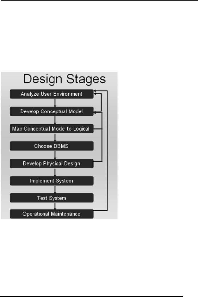
Database
Development Process: Approach
2
There
are other development
processes also with some of
the stages or steps modified
as
compared to
the model we have just
studied. Such and alternative is
given in the Figure-2
below. In
this design process we see
some of the design stages
which existed in the
previous
designing steps but some of
the stages are modified or
merged with others to get
more
precise result or to distinguish
different separate design phases. In
this process of
designing;
the following steps
exist:
Analyze
User Environment
o
Develop
Conceptual Model
o
Map
Conceptual Model to
Logical
o
Choose
DBMS
o
Develop
Physical Design
o
Implement
System
o
Test
System
o
Operational
Maintenance
o
o Analyze
User Environment
This is
same step as we discussed
while discussing the
previous designing
process
o Develop
Conceptual Model
Next
stage in this process model
is the development of conceptual
model or schema Here
we
actually transform the
studied and analyzed information
into the conceptual design
of
the
database, this stage may
also be connected with the
requirement analysis phase,
as
expressed
in the diagram by showing an
arrow from this stage back
to the first stage.
o Map
Conceptual Model to Logical
Model
Third
stage is the mapping of the
developed conceptual model to
the logical model of
the
database,
means at this stage the
schema rules are defined and
identified for
general
database
structures.
o Choose
DBMS
Once
the mapping of the
conceptual and logical model is
done, the decision for
the use of
DBMS is
made; again we refer to the previous
model for selecting of the
DBMS and will
take care
of all the necessary requirements of
the environment before
making a decision.
54
Database
Management System
(CS403)
VU
o Develop
Physical Design
Once we
have selected a DBMS, the
logical design is then transformed
into physical
design.
This also includes considering
many other decisions, like,
data type allocation,
indexes
to be created, file organizations,
etc. Physical database design is
achieved by
using
the DBMS specific rules
for schema definition and
all the facilities provided
by the
DBMS,
Fig: 3.
Database Development Stages. (Second
Approach)
o Implement
System
This
stage is also similar to the one
described earlier, i.e.,
designing the application
for
different
users and user groups of the
organization.
o Test
System
Testing
is important in the sense
that an application may be
producing incorrect
results,
and this
incorrectness may lead to the
inconsistency of the system. So
when a system
55

Database
Management System
(CS403)
VU
design is
complete, once it is implemented it must
be tested for proper
operation and all
the
modules must be checked for
their correctness. Whether the
system modules are
important
or not because the result of
the system is mostly dependent on
the proper the
functionality
of all database applications and
modules.
o Operational
Maintenance:
Maintenance
means to check that all
parts of the system are
working and once the
testing
of the
system is completed the
periodic maintenance measure
are performed on the
system to
keep the system in working
order.
Tools
Used for Database System
Development:
Why tools
are used?
Tools
are used for describing
the design process in standard ways. If
there is no
standardized
tool available for designing
a specific systems; Then
everyone will have to
use
its own design notation, and a
notation used by one designer may
not be
understandable
to the another one. This
misunderstanding can be more drastic if
both the
designers
are working for the
development of the same
system. Tools can also help
the
designer and
the user to mutually agree on a
specific design.
Data
Flow Diagrams:
The
most common tool used
for deigning database systems is Data
Flow Diagram. It is
used to
design systems graphically and expresses
different system detail in
different DFD
levels.
DFDs
show the flow of data
between different processes o a
specific system.
DFDs
are simple, and hide
complexities.
DFDs
are Descriptive and links
between processes describe
the information flow.
o Limitation
of DFDs
They do
not provide us a way of
expressing decision
points.
56

Database
Management System
(CS403)
VU
DFDs
are focused on flow of
information only.
o Symbols
used in DFD:
There
are a limited number of
symbols which are used
for design process in
DFDs.
o DATAFLOW:
The
purpose of the dataflow in a DFD is to
express the flow of
information from one
entity to
another entity in the
system
Data
flows are pipelines through
which packets of information
flow.
Arrows
are labeled with name of the
data that moves through
them. Figure-4 below
show
the
Dataflow diagram
Fig: 4.
Dataflow Symbol
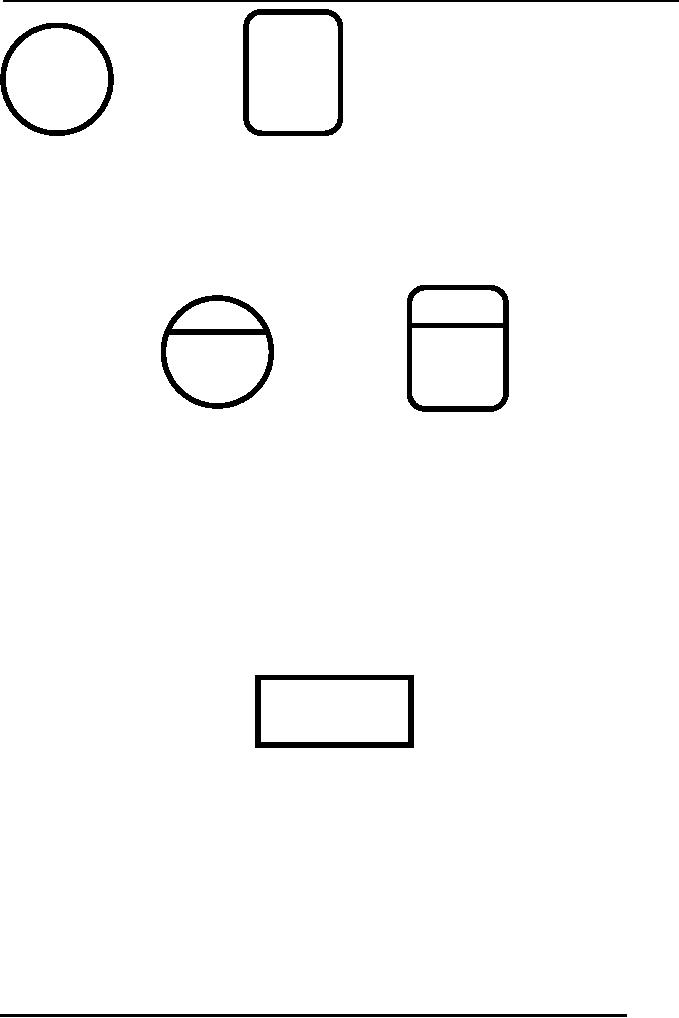
o DATA
STORE:
Data store is a
repository for the storage
of the data. When in a
system the data is to
be
permanently
stored somewhere for future
reference or use the
DATASTORE is used for
this
purpose. It is express with a rectangle
open on right width and left
width of the
rectangle
drawn with double
lines.
Data in
the DATASTORE is held sometimes
for processing purposes also i-e it
may not
be a
permanent data store.. Name
of the DATASTORE is a noun
which tells the
storing
location
in the system. Or identifies
the entity for which
data is stored. Figure-5 shows
a
data
store.
Fig: 5.
Data store
o Processes:
Processes
are expressed with ovals or
rounded rectangles. Processes
are used to express
the
transformation of incoming dataflow
into outgoing dataflow.
Process symbols are
used
for whatever is the action
taking place and whatever is the
magnitude or complexity
of the
action. Simply stating when
data is transformed from one
form into another
the
process
symbol is used. Figure-6a and
Figure-6b show two different
shapes used for
presenting
process in DFD.
57
Database
Management System
(CS403)
VU
Fig:
6a
Process
Fig-6b
o DFD-Process:
In DFD
processes are numbered for
expressing their existence at a
certain level in the
system.
1.0
1.0
Process
Process
Fig: 7.
Numbered DFD
Processes
o External
Entities:
These are
the entities interacting
with the system in any of
two different ways. They
may
be either
receiving the data from
the system, or may be
producing the data for
the system
to
consume.
Shape
used to express external
entities is rectangle. The
shape for external entity
is
shown in
Figure-8.
Fig: 8.
External Entity
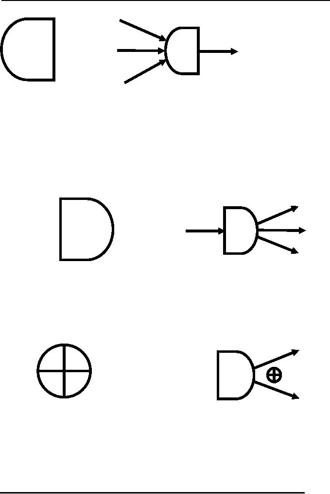
o Collector:
This
DFD shape is used to express
several dataflow connections
terminating at a single
location.
Collector is used to show
the convergence of data to a
single point. Fig 9a
shows
the Collector symbol and Fig
9b show a collector symbol
acting as a sink for
multiple
data flows.
58
Database
Management System
(CS403)
VU
Fig: 9a
Collector
Fig
9b. Collector with Multiple
Dataflow
o Separator:
The
dataflow symbol which is
used for separating data
from a single source to
multiple
sinks is
known as a separator.
Figure
10a show the presentation of
separator and the figure 10b
shows the separator as
it
may
appear in a DFD.
Fig:
10a Separator
Fig
10b. Separator with Multiple
Dataflow
o Ring
Sum Operator:
This
operator is used when data
from a source process can flow to one of
the mentioned
sinks.
For this purpose the symbol
used is displayed in Figure:
11a and its presentation
in
a DFD is
expressed in Figure-11b.
Fig:
11a Ring sum operator
Fig 11b. Separator with
Ring sum operator
o AND
Operator:
This
operator is used when data
from a source process must
flow to all the
connected
sinks.
For this purpose the symbol
used is displayed in Figure:
12a and its presentation
in
a DFD is
expressed in Figure-12b.
59
Database
Management System
(CS403)
VU
Fig:
12a AND operator
Fig
12b. Separator with AND
operator
Types of
DFD
o Context
diagram
o Level 0
diagram
o Detailed
diagram
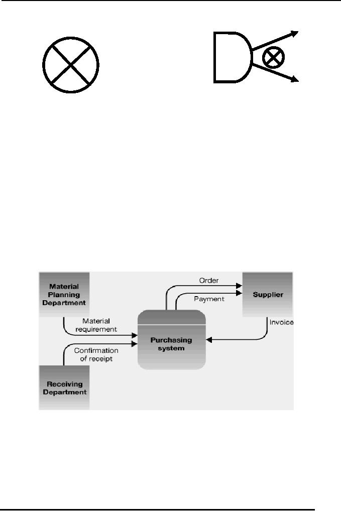
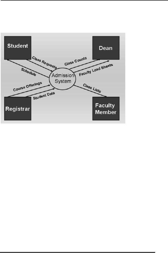
o Context
Diagram:
This is
the level of DFD which
provides the least amount of
details about the working
of
the
system. Context DFDs have
the following
properties:
They
always consist of single
process and describe the
single system. The only
process
displayed
in the CDFDs is the process/system
being analyzed. Name of the
CDFDs is
generally
a Noun Phrase.
Fig:
13a. Example Context DFD
Diagram
No System
details are shown in the
Contexts DFDs just context
is shown. Input and
output
from and to the process are
shown and interactions are
shown only with
the
external
entities. An example DFD at
context level is shown in
Figure: 13a and 13b.
60
Database
Management System
(CS403)
VU
In the
context level DFDs no data
stores are created. Ant
dataflow from external
entities
are
only directed toward the
purported system and vice versa, no
communication is show
between
external entities
themselves.
Fig:
13b. Example Context DFD
Diagram
o Level 0
Data Flow Diagrams:
The
level 0 Diagram in the DFD
is used to describe the
working of the whole
system.
Once a
context DFD has been
created the level zero
diagram or level `not'
diagram is
created.
The level zero diagram
contains all the apparent
details of the system. It
shows
the
interaction between a numbers of
processes and may include a
large number of
external
entities. At this level it is
the duty of the designer to
keep a balance in describing
the
system using the level 0
diagram. Balance means that
he should give proper depth
to
the
level 0 diagram processes.
Because placing too much
details and showing all of
the
miniature
processes in the level 0 diagrams
makes it too much complex.
On the other
hand it
is also not recommended to just
ignore even larger processes
of the system,
because
in such a case although the
level 0 DFD will become
simple but now we
will
have to
create large number of
detail DFDs. So a balance in describing
the system should
be kept
so that the depth of the
Level 0 DFD is manageable.
o Steps in
creating the level 0
DFD
1. Identify distinct
modules of the system for
which to create the
DFD
61

Database
Management System
(CS403)
VU
2. Create DFDs
for all the modules one by
one to show the internal
functionality of
the
system.
3. Once DFD
for the distinct modules of
the system have been
created, establish link
between
different DFDs where
required by either connecting
the entities of the
system,
processes of the system or
the data stores in different
DFDs.
4.
Now
comes
to
the
stage
of
placing
the
numbers
on
processes.
As we
know that the level 0
diagram encompasses a large
number of smaller
systems,
ant is a combination of a number of
context DFDs. In level 0
diagram a
process
when it has a lot of
details, it is not explained
further in the level 0,
and
rather
it
is
postponed
for
the
detailed
diagram.
In the
detailed Data Flow and is given a
number. Numbering processes is
based
on a
specific notation, in the
level 0 diagrams only left
half or the portion
before
the
decimal point is valid but
in the detailed diagram when
a complex process is
expressed
further its sub processes
are number like 1.0,
1.1, and 1.2 and so
on.
62
Table of Contents:
- Introduction to Databases and Traditional File Processing Systems
- Advantages, Cost, Importance, Levels, Users of Database Systems
- Database Architecture: Level, Schema, Model, Conceptual or Logical View:
- Internal or Physical View of Schema, Data Independence, Funct ions of DBMS
- Database Development Process, Tools, Data Flow Diagrams, Types of DFD
- Data Flow Diagram, Data Dictionary, Database Design, Data Model
- Entity-Relationship Data Model, Classification of entity types, Attributes
- Attributes, The Keys
- Relationships:Types of Relationships in databases
- Dependencies, Enhancements in E-R Data Model. Super-type and Subtypes
- Inheritance Is, Super types and Subtypes, Constraints, Completeness Constraint, Disjointness Constraint, Subtype Discriminator
- Steps in the Study of system
- Conceptual, Logical Database Design, Relationships and Cardinalities in between Entities
- Relational Data Model, Mathematical Relations, Database Relations
- Database and Math Relations, Degree of a Relation
- Mapping Relationships, Binary, Unary Relationship, Data Manipulation Languages, Relational Algebra
- The Project Operator
- Types of Joins: Theta Join, Equi–Join, Natural Join, Outer Join, Semi Join
- Functional Dependency, Inference Rules, Normal Forms
- Second, Third Normal Form, Boyce - Codd Normal Form, Higher Normal Forms
- Normalization Summary, Example, Physical Database Design
- Physical Database Design: DESIGNING FIELDS, CODING AND COMPRESSION TECHNIQUES
- Physical Record and De-normalization, Partitioning
- Vertical Partitioning, Replication, MS SQL Server
- Rules of SQL Format, Data Types in SQL Server
- Categories of SQL Commands,
- Alter Table Statement
- Select Statement, Attribute Allias
- Data Manipulation Language
- ORDER BY Clause, Functions in SQL, GROUP BY Clause, HAVING Clause, Cartesian Product
- Inner Join, Outer Join, Semi Join, Self Join, Subquery,
- Application Programs, User Interface, Forms, Tips for User Friendly Interface
- Designing Input Form, Arranging Form, Adding Command Buttons
- Data Storage Concepts, Physical Storage Media, Memory Hierarchy
- File Organizations: Hashing Algorithm, Collision Handling
- Hashing, Hash Functions, Hashed Access Characteristics, Mapping functions, Open addressing
- Index Classification
- Ordered, Dense, Sparse, Multi-Level Indices, Clustered, Non-clustered Indexes
- Views, Data Independence, Security, Vertical and Horizontal Subset of a Table
- Materialized View, Simple Views, Complex View, Dynamic Views
- Updating Multiple Tables, Transaction Management
- Transactions and Schedules, Concurrent Execution, Serializability, Lock-Based Concurrency Control, Deadlocks
- Incremental Log with Deferred, Immediate Updates, Concurrency Control
- Serial Execution, Serializability, Locking, Inconsistent Analysis
- Locking Idea, DeadLock Handling, Deadlock Resolution, Timestamping rules