 |

Database
Management System
(CS403)
VU
Lecture No.
06
Reading
Material
"Database
Systems Principles, Design and
Implementation"
Section
2.4
written
by Catherine Ricardo, Maxwell
Macmillan.
Overview of
Lecture
o Detailed
DFD Diagrams:
o Database
Design Phase
o Data
Models
o Types of
Data Models
o Types of
Database Designs
Detailed
Data Flow Diagram:
This
Type of the Data flow diagrams is
used when we have to further
explain the
functionality
of the processes that we
showed briefly in the Level
0 Diagram. It means
that
generally detailed DFDS are
expressed as the successive
details of those processes
for
which we do not or could not
provide enough
details.
The
symbols and other rules
regarding the detailed DFD
are same as are in other
types of
DFDs.
The special features associated
with this diagram are that,
one, it is optional,
that
is, it is
created for only those
processes from the level 0
diagram for which we want
to
show
the details. For a small
sized system we may not need
to develop even a
single
detailed
DFD, since the level 0
diagram might be covering it
sufficiently. Second
specific
characteristic
of the detailed DFD is its
processes' numbering. Numbering of
processes in
the
detailed DFD is done on the
basis of numbering of the
particular process in level
0
diagrams
whose sub-processes are
being included in the
detailed DFD. For example,
a
specific
process which was numbered in
the level 0 diagram as 1.0
or 1 may have a
number of
sub-processes since we did not represent
the process 1.0 in detail in
level 0
diagrams. So in
the detailed dataflow
diagram we create sub-processes of
that process
and then
number all the sub processes
of that specific process as
the sublets of the
process.
63

Database
Management System
(CS403)
VU
Numbering
of such sub processes is done as 1.1,
1.2, and 1.3... for first
second and third
sub-processes
of the process 1.0
respectively. The phenomenon of
creating sub-processes
does
not end at creating a few
sub-processes for a specific
process shown at level
0
diagrams.
Rather it may continue
deeper if there is requirement
for further explanation
of
the
any process or sub-processes. In
such a case when we create
sub-process of a sub-
process
1.2 then the numbering is
done in further extension of that
specific sub processes
number
and example of such a numbering
process is 1.2.1, 1.2.2,
1.2.3,...
Another
point that is worth
mentioning here is that we call
processes in the
detailed
DFDs as
sub-processes, but they are
sub-processes only in reference to
the process whose
details
they are explaining
otherwise they are just
like processes; transforming
some input
data
into some form of output.
The sub-processes may be
performing relatively
small
amount of
operations, still they are
processes.
Maximum
Number of Process in a DFD
should not be very huge.
Having a moderate
number
for a detailed DFD is also recommended
because it adds clarity to
our detailed
data
flow diagram. For clarity
propose it is good to have a maximum of 7
or 9 processes
in one
detailed DFD. Moreover all
the processes, sub processes,
data stores, entities
data
flows and
all other components of the
DFD must be named properly, so
that anyone who
is using
this DFD should be able to
understand the DFD
easily.
In all
the levels of DFD it must be
considered that all the
processes have data inputs
as
well as
data outputs. Data being sent to one
process should be processed so
that it
changes
its form and transforms from
one form to another.
When
creating a detailed diagram
the data inputs and data
outputs must be in
coincidence,
mean in
both the diagrams the data
input to a process and data
output in the form of
data
flows
must be same.
Data
Dictionary
A
database that containing
data about all the
databases in the database
system. Data
dictionaries
store all the various schema
and file specifications and their
locations. They
also
contain information about
which programs use which
data and which users
are
interested in
which reports.
Types of
Data Dictionaries:
o Integrated
There
are basically two types of
data dictionaries which are
available for use by a
DBMS,
with
respect to their
existence.
64

Database
Management System
(CS403)
VU
The
first type of data
dictionary in this context is
the integrated data
dictionary. Such a
data
dictionary is place embedded into
the database system, and is
created by the DBMS
for
its usage under the
directions and requirements provided by
the DBA
As the
DBMS needs to talk with
the "three level
architecture" of database and
mapping
information
along with all the
database design information lies in
the database schema.
The
DBMS uses the data
dictionary to access the
database at each layer or
model, for this
purpose
the data dictionary of any
type can be used but the
integrated data dictionary
is
far
more efficient than any
free standing data
dictionary because an integrated
data
dictionary
is created by the DBMS
itself and uses the same
data accessing techniques
etc.
o Free
Standing
Second
type of data dictionary is
free standing data
dictionary create by any
CASE tool
and then
attached to the database management
systems. A number of case tools
are
available
for this purpose and help user
designing the database and
the database
applications
as well in some modern forms
of the CASE tools.
Cross
Reference Matrix
This is a
tool available in the data
dictionary and helps us in finding
entities of the
database
and their associations. CRM is developed
at the designing stage of
the database;
we can
say that at the time of
creation of the user views of
reports for certain users
we
identify
the material required by the
users. In the cross reference
matrix, on the Y axis
we
specify
the accessible components of
the database such as
transitions, reports, or
database
objects
and on the x axis we specify
the attributes that will be
accessed in the
corresponding
accessed object.
Now
the matrix gets a shape of
two dimensional arrays on
which we have
accessible
objects
of the database and on the
other hand we have the
elements which are
available
for
access through those objects.
Then whichever data item is
accessible through a
certain
object we
place a tick on the intersection of
that row and column and thus
we can easily
identify
the deferent items accessed
in different reports.
65
Database
Management System
(CS403)
VU
A
C
c
T
S
t
l
C
r
e
t
a
a
a
m
e
s
s
n
R
n
s
s
s
e
d
R
R
c
s
S
e
e
r
C
h
s
s
i
a
e
S
u
p
r
e
u
l
t
d
t
b
t
courseName
√
√
√
cumulativeGPA
√
√
√
√
√
√
√
date
√
√
fatherName
√
finalMarks
√
√
grade
√
√
√
√
grdPoint
√
√
marks
√
midTerm
programName
√
√
√
√
√
semesterGPA
√
√
√
√
√
√
√
√
semesterNo
√
√
√
semName
√
√
session
√
sessMarks
√
√
stName
√
√
stNames
stRegistration
√
√
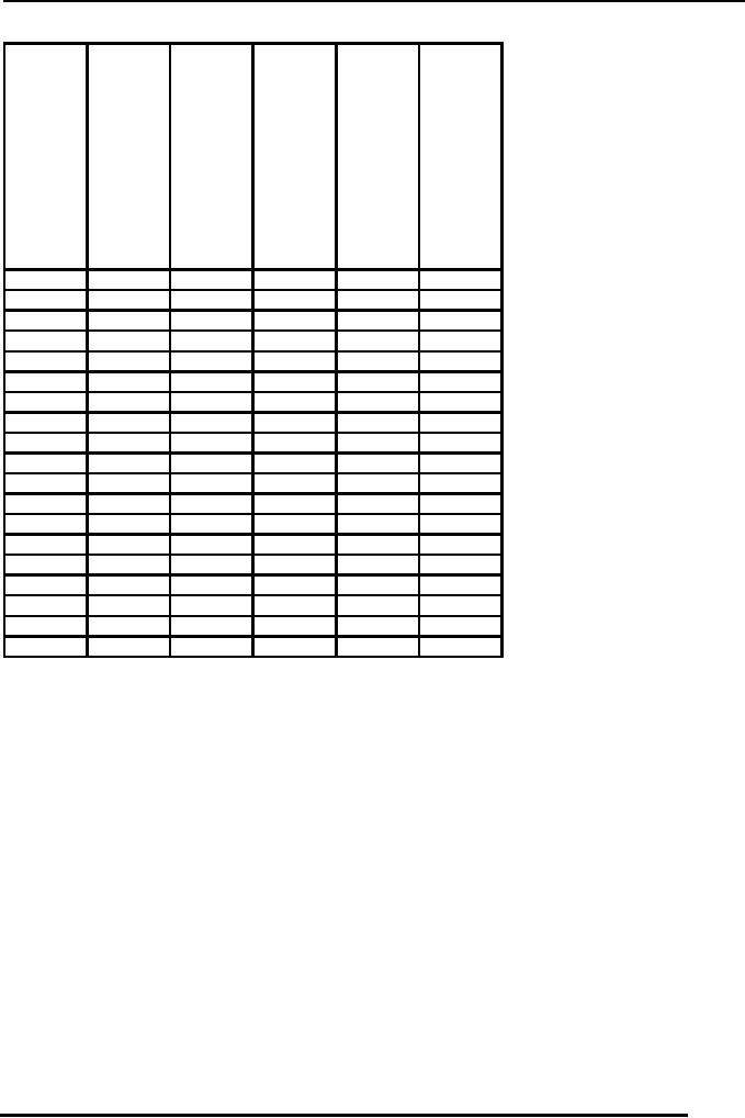
Table 1:
An example cross reference
matrix
The
cross reference matrix shown
in table 1 lists different
attributes against different
reports
required by different user groups of an
exam system. Rows in this
matrix contain
different
attributes and the columns
contain different reports.
Now the tick mark in
the
cells
represents the use or
presence of attributes in different
reports. This matrix
represents, on one
side, the relative
importance or use of different
attributes. On the
other
hand it
also helps to identify different
entity types and their
defining attributes.
The
attributes
that are represented
collectively on one or more reports
are candidates of
combining
into a single entity type.
Although it is necessary that
attributes appearing
together
should be grouped into same
entity type, but still
they are candidates
for
combining
into the one.
Data
Dictionary in not very necessary
for using such a cross
reference matrix, instead
for
relatively
small systems it can be created
manually.
Outcome
of the Analysis Phase
66

Database
Management System
(CS403)
VU
In the
preliminary study phase,
database designers collect
information about the
existing
system
from the users of the
system. For this purpose
they may interview different
users
or concerned persons,
or they may distribute
questionnaires among different
users and
ask
them to fill them in and later
may use these questionnaires
in the analysis
phase.
Designers represent
their understanding of the
working of existing system in
the form of
DFDs and
discuss it with the users to
make it sure that they have
understood all details
of
the
existing system and the
requirements of different users
groups.
The
DFDs are input to the
analysis phase, where
designers analyze the
requirements of
the
users and establish the
procedure to meet those requirements.
From the database
perspective,
in the analysis phase
designers have to identify
the facts or data that
is
required
to be stored in order to fulfill the
users' requirements. For
this purpose they may
use
some CASE tools, like
cross reference matrix.
Generally, in the analysis
phase,
designers
prepare a draft or initial
database design that they
ultimately finalize in the
next
phase,
that is, the database design
phase. So in short we can say,
that DFDs are the
output
of the
preliminary phase and are
input to the analysis phase.
The initial design or a
draft
form of
design (generally in entity-relationship
data model) is the output of
the analysis
phase and
input to the design phase. In
the design phase, then you
finalize the design.
The
sequence of the activities
mentioned above is not much
important, however,
the
activities
mentioned are important and
must be performed in order to
have a correct
database
or database application design. In the
following lectures, we are
going to study
different
tools that are used in
the design phase, that is,
the data models. We will
be
studying,
both, the data models and
their implementation in the
database design phase.
Database
Design Phase
Database
design phase follows the
analysis phase. Before
starting the discussion on
the
design
activity, it will be wise if we clearly
understand some basic concepts
that are
frequently
used in this phase.
o Database
Design /Database
Model
These
terms can be used interchangeably
for the logical structure of
the database. The
database
design/model stores the
structure of the data and
the links/relationships
between
data
that should be stored to meet the
users' requirements. Database design is
stored in
the
database schema, which is in turn stored
in the data
dictionary.
o Database
Modeling
The
process of creating the
logical structure of the
database is called database
modeling.
It is a
very important process
because the designing of the
application provides us
the
basis
for running our database
system. If the database is
not designed properly
the
implementation
of the system can not be done
properly. Generally the design of
the
database
is represented graphically because it
provides an ease in design and
adds
flexibility
for the understanding of the
system easily.
67

Database
Management System
(CS403)
VU
Data
Model
Data
model is a set or collection of
construct used for creating
a database and producing
designs
for the databases. There
are a few components of a
data model:
o Structure:
What
structures can be used to store the
data is identified by the
structures provided by
the
data model
structures.
o Manipulation
Language
For
using a certain model
certain data manipulations
are performed using a
specific
language.
This specific language is
called data manipulation
language.
o Integrity
Constraints
These are
the rules which ensure the
correctness of data in the database and
maintain the
database
in usable state so that correct
information is portrayed in designing
the database.
Generally
these components are not
explicitly defined in data
models, they may be
available
in some of the modern DBMSs
but in traditional and general
model, these may
not be
available.
Significance
of the Data Model
Data
model is very important tool
because it is something which is
sued for designing
the
database
for a DBMS and no DBMS can
exist independent of any
data model, now if we
use a
specific DBMS but are
not sure about the data
model it uses for data
abase usage,
we can
not create a proper
database.
As a
specific DBMS is base on the
use of a specific data model
so when using a DBMS
it
is of great
use to know that what
structures, manipulation languages and
integrity
constraints
are implemented by a specific
DBMS. As it is the only way
to know the
facilities
and functionalities offered by the
DBMS.
This is
the reason whenever we get a
specific DBMS, it is explicitly
mentioned with that
DBMS,
that which data model
this DBMS uses.
Types of
Data Models
o Semantic
Data Model
These are
the data models which
provide us better flexibility in
implementing constraints,
better
language utilities and better
data structure constructs. As a
result actions
performed
using
proper data and structure
tools gives us better data
designing and manipulation
facilities.
A better data model provides
better opportunities to express
multiple situations
in the
database design and as a result get
better output from the
tool or model in the
form
of a
better database
design.
�
ER- Data
Model
�
Object
oriented data model
68

Database
Management System
(CS403)
VU
� Record
Based Data Model
This is
the second type of data
models available to use and
has three basic
types
�
Hierarchical
Data Model
�
Network
Data model
�
Relational
Data model
These
models are records based and
are not in similarity with
those of semantic data
models.
These models handle the data
at almost all the three
level of the three layers
of
the
database architecture. Semantic
data models are generally
used for designing
the
logical
or conceptual model of the
database system, once very
common example of the
semantic
data model is ER-Data Model
and is very much popular for
designing databases.
No DBMS
is based on ER Data model because it is
purely used for designing
whereas a
number of
DBMS are available based on
OO data model, network data
model, relational
data
model l and hierarchical data
model.
Types of
Database Design
Conceptual
database design
This
design is implemented using a semantic
data model, for example
for creating a
design
for an organization database we can
use and we do use the
ER-Data model.
Logical
Database design
This
design is performed using a data
model for which we have a
DBMS available and
we are
planning to run our database
system that DBMS.
Physical
Database Design:
The
Logical design created using a
specific data model and
created after the analysis
of
the
organization, it needs to be implemented
in a physical DBMS software so
the
Physical
database design is performed and the
design created so far in the
logical form
are
implemented on that very
DBMS.
By separating
the three design levels we
get the benefit of
abstraction on one hand
whereas on
the other hand we can create
our logical and conceptual
designs using better
design
tools, which would have
not been possible if we are
using the same design-tool
for
al the
three levels. Moreover if in
future there is a need to make a change
in the physical
implementation
of the data we will have to make no
changes in the logical or
conceptual
level of
the database design , rather
the change can be achieved by only
using the existing
conceptual
model and implementing it again on
Physical model using a
separate DBMS.
69
Table of Contents:
- Introduction to Databases and Traditional File Processing Systems
- Advantages, Cost, Importance, Levels, Users of Database Systems
- Database Architecture: Level, Schema, Model, Conceptual or Logical View:
- Internal or Physical View of Schema, Data Independence, Funct ions of DBMS
- Database Development Process, Tools, Data Flow Diagrams, Types of DFD
- Data Flow Diagram, Data Dictionary, Database Design, Data Model
- Entity-Relationship Data Model, Classification of entity types, Attributes
- Attributes, The Keys
- Relationships:Types of Relationships in databases
- Dependencies, Enhancements in E-R Data Model. Super-type and Subtypes
- Inheritance Is, Super types and Subtypes, Constraints, Completeness Constraint, Disjointness Constraint, Subtype Discriminator
- Steps in the Study of system
- Conceptual, Logical Database Design, Relationships and Cardinalities in between Entities
- Relational Data Model, Mathematical Relations, Database Relations
- Database and Math Relations, Degree of a Relation
- Mapping Relationships, Binary, Unary Relationship, Data Manipulation Languages, Relational Algebra
- The Project Operator
- Types of Joins: Theta Join, Equi–Join, Natural Join, Outer Join, Semi Join
- Functional Dependency, Inference Rules, Normal Forms
- Second, Third Normal Form, Boyce - Codd Normal Form, Higher Normal Forms
- Normalization Summary, Example, Physical Database Design
- Physical Database Design: DESIGNING FIELDS, CODING AND COMPRESSION TECHNIQUES
- Physical Record and De-normalization, Partitioning
- Vertical Partitioning, Replication, MS SQL Server
- Rules of SQL Format, Data Types in SQL Server
- Categories of SQL Commands,
- Alter Table Statement
- Select Statement, Attribute Allias
- Data Manipulation Language
- ORDER BY Clause, Functions in SQL, GROUP BY Clause, HAVING Clause, Cartesian Product
- Inner Join, Outer Join, Semi Join, Self Join, Subquery,
- Application Programs, User Interface, Forms, Tips for User Friendly Interface
- Designing Input Form, Arranging Form, Adding Command Buttons
- Data Storage Concepts, Physical Storage Media, Memory Hierarchy
- File Organizations: Hashing Algorithm, Collision Handling
- Hashing, Hash Functions, Hashed Access Characteristics, Mapping functions, Open addressing
- Index Classification
- Ordered, Dense, Sparse, Multi-Level Indices, Clustered, Non-clustered Indexes
- Views, Data Independence, Security, Vertical and Horizontal Subset of a Table
- Materialized View, Simple Views, Complex View, Dynamic Views
- Updating Multiple Tables, Transaction Management
- Transactions and Schedules, Concurrent Execution, Serializability, Lock-Based Concurrency Control, Deadlocks
- Incremental Log with Deferred, Immediate Updates, Concurrency Control
- Serial Execution, Serializability, Locking, Inconsistent Analysis
- Locking Idea, DeadLock Handling, Deadlock Resolution, Timestamping rules