 |
AN OVERVIEW & NUMBER SYSTEMS |
| Binary to Decimal to Binary conversion, Binary Arithmetic, 1s & 2s complement >> |

CS302 -
Digital Logic & Design
Lesson
No. 01
AN OVERVIEW &
NUMBER SYSTEMS
Analogue
versus Digital
Most of
the quantities in nature
that can be measured are
continuous. Examples
include
· Intensity of
light during the day:
The
intensity of light gradually
increases as the sun
rises in
the morning; it remains
constant throughout the day
and then gradually
decreases
as the
sun sets until it becomes
completely dark. The change
in the light throughout
the
day is
gradual and continuous. Even
with a sudden change in
weather when the sun
is
obscured by a
cloud the fall in the
light intensity although
very sharp however is
still
continuous
and is not abrupt.
· Rise
and fall in temperature
during a 24-hour period: The
temperature also rises
and
falls
with the passage of time
during the day and in
the night. The change in
temperature is
never
abrupt but gradual and
continuous.
· Velocity of
a car travelling from A to B:
The
velocity of a car travelling
from one city to
another
varies in a continuous manner.
Even if it abruptly accelerates or
stops suddenly,
the
change in velocity seemingly
very sudden and abrupt is
never abrupt in reality.
This
can be
confirmed by measuring the
velocity in short time
intervals of few
milliseconds.
The
measurable values generally
change over a continuous
range having a minimum
and
maximum
value. The temperature
values in a summer month
change between 23 0C to 45
0C.
A car
can travel at any velocity
between 0 to 120 mph.
Digital
representing of quantities
Digital
quantities unlike Analogue
quantities are not
continuous but represent
quantities
measured at
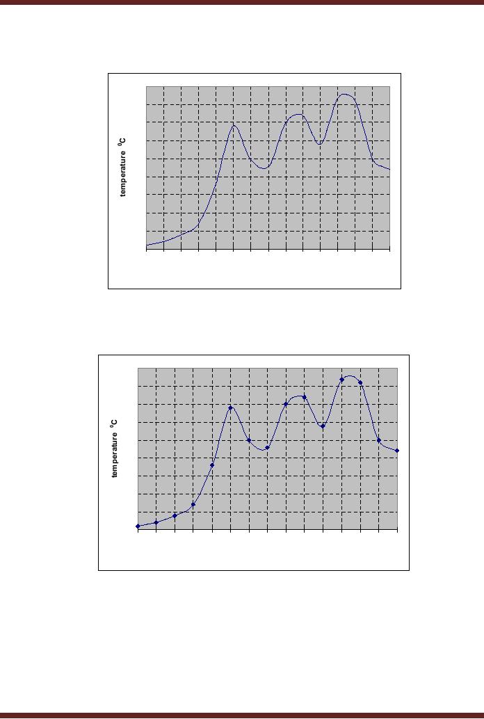
discrete intervals. Consider
the continuous signal as
shown in the figure
1.1.
To represent
this signal digitally the
signal is sampled at fixed
and equal intervals.
The
continuous
signal is sampled at 15 fixed
and equal intervals. Figure
1.2. The set of values
(1,
2, 4, 7, 18,
34, 25, 23, 35,
37, 29, 42, 41, 25
and 22) measured at the
sampling points
represent
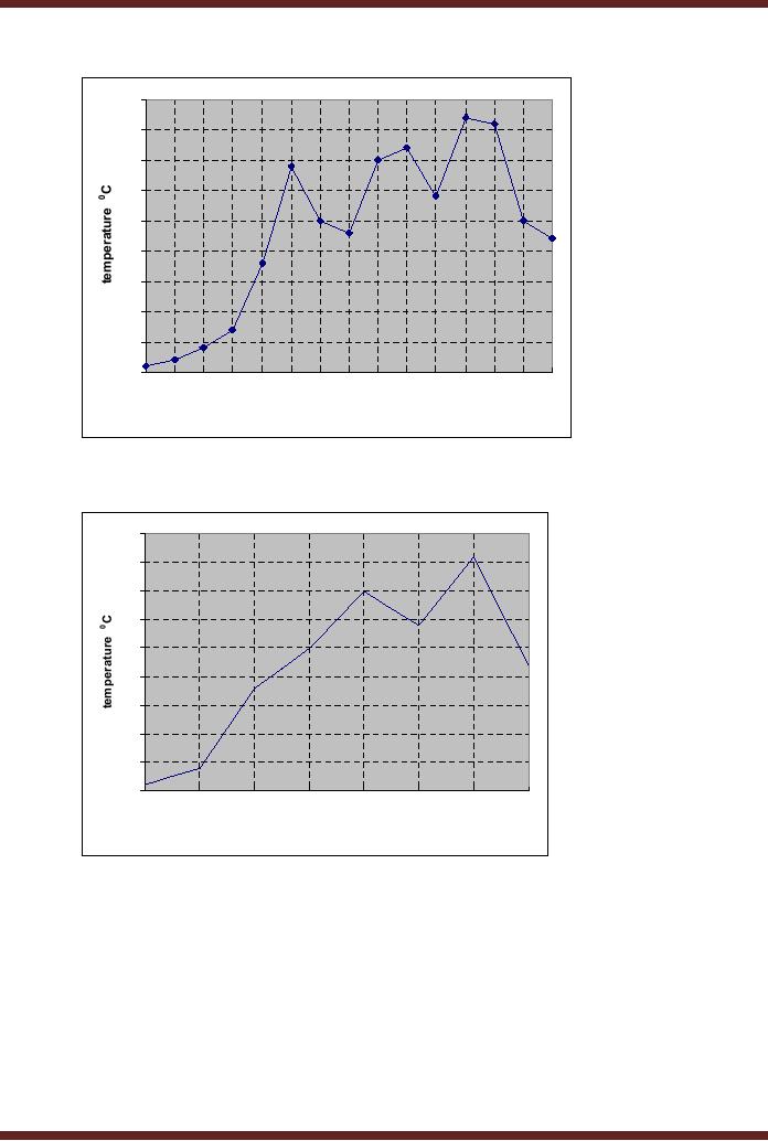
the continuous signal. The
15 samples do not exactly
represent the original
signal
but
only approximate the
original continuous signal.
This can be confirmed by
plotting the 15
sample
points. Figure 1.3. The
reconstructed signal from
the 15 samples has sharp
corners
and
edges in contrast to the
original signal that has
smooth curves.
If the
number of samples that are
collected is reduced by half,
the reconstructed signal
will
be very
different from the original.
The reconstructed signal
using 7 samples have
missing
peak
and dip at 34 0C and
23 0C respectively.
Figure 1.4. The reason
for the difference
between
the original and the
reconstructed signal is due to
under-sampling. A more
accurate
representation
of the continuous signal is
possible if the number of
samples and sampling
intervals
are increased. If the
sampling is increased to infinity
the number of values would
still
be discrete
but they would be very
close and closely match
the actual signal.
1
CS302 -
Digital Logic & Design
45
40
35
30
25
20
15
10
5
0
1
2
3
4
5
6
7
8
9
10
11
12
13
14
15
time
Figure
1.1 Continuous signal
showing temperature varying
with time
45
42
41
40
37
35
35
34
30
29
25
25
25
23
22
20
18
15
10
7
5
4
2
1
0
1
2
3
4
5
6
7
8
9
10
11
12
13
14
15
time
Figure
1.2 Sampling the Continuous
Signal at 15 equal
intervals
2
CS302 -
Digital Logic & Design
45
42
41
40
37
35
35
34
30
29
25
25
25
23
22
20
18
15
10
7
5
4
2
1
0
1
2
3
4
5
6
7
8
9
10
11
12
13
14
15
samples
Figure
1.3 Reconstructed Signal by
plotting 15 sampled
values
45
40
35
30
25
20
15
10
5
0
1
3
5
7
9
11
13
15
samples
Figure
1.4 Reconstructed Signal by
plotting 7 sampled
values
Electronic
Processing of Continuous and
Digital Quantities
Electronic
Processing of the continuous
quantities or their Digital
representation requires
that
the continuous signals or
the discrete values be
converted and represented in
terms of
voltages.
There are basically two
types of Electronic Processing
Systems.
· Analogue
Electronic Systems: These
systems accept and process
continuous signals
represented in
the form continuous voltage
or current signals. The
continuous quantities
are
converted into continuous
voltage or current signals by
transducers. The block
diagram
describes
the processing by an Analogue
Electronic System. Figure
1.5.
3

CS302 -
Digital Logic & Design
·
Digital
Electronic Systems: These
systems accept and process
discrete samples
representing
the actual continuous
signal. Analogue to Digital
Converters are used
to
sample
the continuous voltage
signals representing the
original signal.
Do the
Digital Electronic Systems
use voltages to represent
the discrete samples of
the
continuous
signal? This question can be
answered by considering a very
simple example of a
calculator
which is a Digital Electronic
System. Assume that a
calculator is calibrated to
represents
the number 1 by 1 millivolt
(mV). Thus the number 39 is
represented by the
calculator in
terms of voltage as 39 mV.
Calculators can also
represent large numbers such
as
6.25 x
1018 (as in 1 Coulomb =
6.25 x 10¹⁸
electrons).
The value in terms of volts
is 6.25 x 10¹⁵
volts!
This voltage value can
not be practically represented by
any electronic circuit.
Thus
Digital
Systems do not use discrete
samples represented as voltage
values.
Figure
1.5
Analogue
Electronic System processing
continuous quantities
Digital
Systems and Digital
Values
Digital
systems are designed to work
with two voltage values. A
+5 volts represents a
logic
high
state or logic 1 state and 0
volts represents a logic low
state or logic 0 state. The
Digital
Systems
which are based on two
voltage values or two states
can easily represent any
two
values.
For example,
· The
numbers `0' and
`1'
· The
state of a switch `on' or
`off'
· The
colour `black' and
`white'
· The
temperature `hot' and
`cold'
· An object
`moving' or `stationary'
Representing
two values or two states is
not very practical, as many
naturally occurring
phenomenons
have values or state that
are more than two.
For example, numbers
have
widely
varying ranges, a colour
palette might have 64
different shades of the
colour red, the
temperature of
boiling water at room
temperature varies from 30 0C to 100 0C.
Digital Systems
are
based on the Binary Number
system which allows more
than two or multiple values
to be
represented
very conveniently.
Binary
Number System
4

CS302 -
Digital Logic & Design
The
Binary Number System unlike
the Decimal number system is
based on two values.
Each
digit or bit in Binary
Number system can represent
only two values, a `0'
and a `1'. A
single
digit of the Decimal Number
system represents 10 values, 0, 1, 2 to
9. The Binary
Number
System can be used to
represent more than two
values by combining binary
digits or
bits. In a
Decimal Number System a
single digit can represent
10 different values (0 to
9),
representing
more than 10 values requires
a combination of two digits
which allows up to
100
values to be
represented (0 to 99). A Combination of
Binary Numbers is used to
represent
different
quantities.
·
Represent
Colours: A palette of
four colours red, blue,
green and yellow can
be
represented by a
combination of two digital
values 00, 01, 10 and 11
respectively.
Representing
Temperature: An analogue
value such as 39oC can
be represented in a
·
digital
format by a combination of 0s and
1s. Thus 39 is 100111 in
digital form.
Any quantity
such as the intensity of
light, temperature, velocity,
colour etc. can be
represented
through digital values. The
number of digits (0s and
1s) that represents a
quantity
is proportional
to the range of values that
are to be represented. For
example, to represent a
palette of
eight colours a combination of
three digits is used.
Representing a temperature
range of
00 C to 1000 C requires a combination of up to
seven digits.
Digital
Systems uses the Binary
Number System to represent
two or multiple
values,
stores
and processes the binary
values in terms of 5 volts
and 0 volts. Thus the
number 39
represented in
binary as 100111 is stored
electronically in as +5 v, 0v, 0v, +5 v,
+5 v and +5 v.
Advantages of
working in the Digital
Domain
Handling
information digitally offers
several advantages. Some of
the merits of a
digital
system
are spelled out. Details of
some these aspects will be
discussed and studied in
the
Digital
Logic Design course. Other
aspects will be covered in
several other
courses.
· Storing
and processing data in the
digital domain is more
efficient: Computers
are
very
efficient in processing massive
amounts of information and
data. Computers
process
information
that is represented digitally in
the form of Binary Numbers.
A Digital CD stores
large
number of video and audio
clips. Sam number of audio
and video clips if stored
in
analogue
form will require a number
of video and audio
cassettes.
· Transmission
of data in the digital form
is more efficient and
reliable: Modern
information
transmission techniques are
relying more on digital
transmission due to
its
reliability as
it is less prone to errors.
Even if errors occur during
the transmission
methods
exist
which allow for quick
detection and correction of
errors.
· Detecting
and Correcting errors in
digital data is easier: Coding
Theory is an area
which
deals with implementing
digital codes that allow
for detection and correction
of multi-
bit
errors. In the Digital Logic
Design course a simple
method to detect single bit
errors
using
the Parity bit will be
considered.
· Data
can be easily and precisely
reproduced: The
picture quality and the
sound quality
of digital
videos are far more
superior to those of analogue
videos. The reason being
that
the
digital video stored as
digital numbers can be
exactly reproduced where as
analogue
video is
stored as a continuous signal
can not be reproduced with
exact precision.
· Digital
systems are easy to design
and implement: Digital
Systems are based on
two-
state
Binary Number System.
Consequently the Digital
Circuitry is based on the
two-
voltage
states, performing very
simple operations. Complex
Microprocessors are
implemented
using simple digital
circuits. Several simple
Digital Systems will be
discussed
in the
Digital Logic course.
5

CS302 -
Digital Logic & Design
·
Digital
circuits occupy small space:
Digital
circuits are based on two
logical states.
Electronic
circuitry that implements
the two states is very
simple. Due to the
simplicity of
the
circuitry it can be easily
implemented in a very small
area. The PC motherboard
having
an area of
approximately 1 sq.ft has
most of the circuitry of a
powerful computer. A
memory
chip small enough to be held
in the palm of a hand is
able to store an
entire
collection of
books.
Information
Processing by a Digital
System
A Digital
system such as a computer
not only handles numbers
but all kinds of
information.
· Numbers:
A
computer is able to store
and process all types of
numbers, integers,
fractions
etc.
and is able to perform
different kinds of arithmetic
operations on the
numbers.
· Text:
A
computer in a news reporting
room is used to write and
edit news reports. A
Mathematician
uses a computer to write
mathematical equations explaining
the dissipation
of heat by a
heat sink. The computer is
able to store and process
text and symbols.
· Drawings,
Diagrams and Pictures: A computer
can store very conveniently
complex
engineering
drawings and diagrams. It
allows real life still
pictures or videos to be
processed
and edited.
· Music
and Sound: Musicians
and Composers uses\ a
computer to work on a
new
compositions.
Computers understand spoken
commands.
A Digital
System (computer) is capable of
handling different types of
information, which is
represented in
the form of Binary Numbers.
The different types of
information use
different
standards
and binary formats. For
example, computers use the
Binary number system
to
represent
numbers. Characters used in
writing text are represented
through yet another
standard
known as ASCII which allows
alphabets, punctuation marks
and numbers to be
represented
through a combination of 0s and
1s.
Digital
Components and their
internal working
Digital
system process binary
information electronically through
specialized circuits
designed
for handling digital
information. These circuits as
mentioned earlier operate
with two
voltage
values of +5 volts and 0
volts. These specialized
electronic circuits are
known as Logic
Gates
and are considered to be the
Basic Building Blocks of any
Digital circuit.
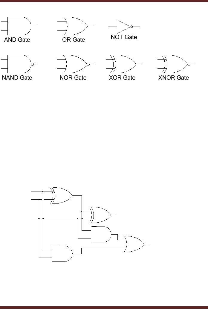
The
commonly used Logic Gates
are the AND gate, the OR
gate and the Inverter or
NOT
Gate.
Other gates that are
frequently used include NOR,
NAND, XOR and XNOR.
Each of
these
gates is designed to perform a
unique operation on the
input information which is
known
as a logical or
Boolean operation.
Large
and complex digital system
such as a computer is built
using combinations of
these
basic
Logic Gates. These basic
building blocks are
available in the form of
Integrated Circuit or
ICs.
These gates are implemented
using standard CMOS and
TTL technologies that
determine
the operational characteristics of
the gates such as the
power dissipation,
operational
voltages (3.3v or 5 v),
frequency response
etc.
6
CS302 -
Digital Logic & Design
Figure
1.6 Symbolic representations of
logic gates.
Combinational
Logic Circuits and
Functional Devices
The
logic gates which form
the basic building blocks of
a digital system are
designed to
perform
simple logic operations. A
single logic gate is not of
much use unless it is
connected
with
other gates to collectively
act upon the input
data. Different gates are
combined to build a
circuit
that is capable of performing
some useful operation like
adding three numbers.
Such
circuits
are known as Combinational
Logic Circuits or Combinational
Circuits. An Adder
Combinational
Circuit that is able to add
two single bit binary
numbers and give a single
bit
Sum
and Carry output is shown.
Figure 1.7.
Implementing
large digital system by
connecting together logic
gates is very tedious
and
time
consuming; the circuit
implemented occupies large
space, are power hungry,
slow and
are
difficult to troubleshoot.
A
P
B
∑
Cin
Cout
G
Figure
1.7 1-bit Full-Adder
Combinational Circuit
Digital
circuits to perform specific
functions are available as
Integrated Circuits for
use.
Implementing a
Digital system in terms of
these dedicated functional
units makes the
system
more
economical and reliable.
Thus an adder circuit does
not have to be implemented
by
connecting
various gates, a standard
Adder IC is available that
can be readily used.
Other
7
CS302 -
Digital Logic & Design
commonly
used combinational functional
devices are Comparators,
Decoders, Encoders,
Multiplexers
and Demultiplexers.
Sequential
logic and
implementation
Digital
systems are used in vast
variety of industrial applications
and house hold
electronic
gadgets. Many of
these digital circuits
generate an output that is
not only dependent on
the
current
input but also some
previously saved information
which is used by the digital
circuit.
Consider
the example of a digital
counter which is used by
many digital applications
where a
count
value or the time of the
day has to be displayed. The
digital counter which
counts
downwards
from 10 to 0 is initialized to the
value 10. When the
counter receives an
external
signal in
the form of a pulse the
counter decrements the count
value to 9. On receiving
successive
pulses the counter
decrements the currently
stored count value by one,
until the
counter
has been decremented to 0. On
reaching the count value
zero, the counter
could
switch
off a washing machine, a
microwave oven or switch on an
air-conditioning system.
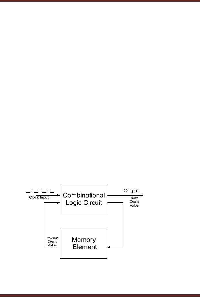
The
counter stores or remembers
the previous count value.
The new count value
is
determined by
the previously stored count
value and the new
input which it receives in
the
form of a
pulse (a binary 1). The
diagram of the counter
circuit is shown in the
figure. Figure
1.8.
Digital
circuits that generate a new
output on the basis of some
previously stored
information
and the new input
are known as Sequential
circuits. Sequential circuits
are a
combination of
Combinational circuits and a
memory element which is able
to store some
previous
information. Sequential circuits
are a very important part of
digital systems. Most
digital
systems have sequential
logic in addition to the
combinational logic. An example
of
sequential
circuits is counters such as
the down-counter which
generates a new
decremented
output
value based on the previous
stored value and an external
input. The storage element
or
the
memory element which is an
essential part of a sequential
circuit is implemented a
flip-flop
using a
very simple digital circuit
known as a flip-flop.
Figure
1.8
A Counter
Sequential Circuit
Programmable
Logic Devices
(PLDs)
The
modern trend in implementing
specialized dedicated digital
systems is through
configurable
hardware; hardware which can
be programmed by the end
user. A digital
8

CS302 -
Digital Logic & Design
controller
for a washing machine can be
implemented by connecting together
pieces of
combinational
and sequential functional
units. These implementations
are reliable however
they
occupy considerable space.
The implementation time also
increases. A general
purpose
circuit
that can be programmed to
perform a certain task like
controlling a washing
machine
reduces
the implementation cost and
time.
Cost is
incurred on implementing a digital
controller for a washing
machine which
requires
that an
inventory of all its
components such as its logic
circuits, functional devices
and the
counter
circuits be maintained. The
implementation time is significantly
high as all the
circuit
components
have to be placed on a circuit
board and connected
together. If there is a
change
in the
controller circuit the
entire circuit board has to
be redesigned. A PLD based
washing
machine
controller does not require
a large inventory of components to be
maintained. Most of
the
functionality of the controller
circuit is implemented within a
single PLD integrated
circuit
thereby
considerably reducing the
circuit size. Changes in the
controller design can be
readily
implemented by
programming the PLD.
Programmable
Logic Devices can be used to
implement Combinational and
Sequential
Digital
Circuits.
Memory
Memory
plays a very important role
in Digital systems. A research
article being edited by
a
scientist on a
computer is stored electronically in
the digital memory whilst
changes are being
made to
the document. Once the
document has be finalized
and stored on some media
for
subsequent
printing the memory can be
reused to work on some other
document. Memory
also
needs to store information
permanently even when the
electrical power is turned
off.
Permanent
memories usually contain
essential information required
for operating the
digital
system.
This important information is
provided by the manufacturer of a
digital system.
Memory is
organized to allow large
amounts of data storage and
quick access. Memory
(ROM)
which permanently stores
data allows data to be read
only. The Memory does
not allow
writing of
data. Volatile memory (RAM)
does not store information
permanently. If the
power
supplied to
the RAM circuitry is turned
off, the contents of the RAM
are permanently lost
and
can
not be recovered when power
is restored. RAM allows reading
and writing of data.
Both
RAM and ROM
are an essential part of a
digital system.
Analogue to
Digital and Digital to
Analogue conversion and
Interfacing
Real-world
quantities as mention earlier
are continuous in nature and
have widely varying
ranges.
Processing of real-world information
can be efficiently and
reliably done in the
digital
domain.
This requires real-world
quantities to be read and
converted into equivalent
digital
values
which can be processed by a
digital system. In most
cases the processed output
needs
to be converted
back into real-world
quantities. Thus two
conversions are required,
one from
the
real-world to the digital
domain and then back
from the digital domain to
the real-world.
Modern
digitally controlled industrial
units extensively use
Analogue to Digital (A/D)
and
Digital to
Analogue (D/A) converters to
covert quantities represented as an
analogue voltage
into an
equivalent digital representation
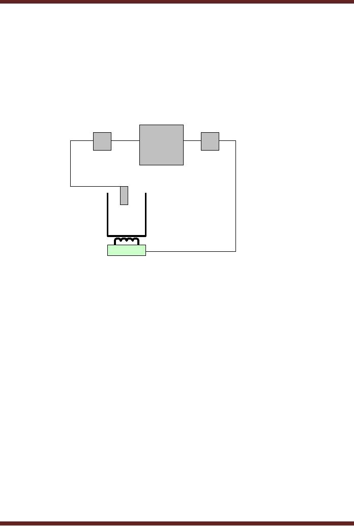
and vice versa. Consider
the example of an
industrial
controller
that controls a chemical
reaction vessel which is
being heated to expedite
the
chemical
reaction. Figure 1.9.
Temperature of the vessel is
monitored to control the
chemical
reaction. As
the temperature of the
vessel rises the heat
has to be reduced by a
proportional
9
CS302 -
Digital Logic & Design
level. An
electronic temperature sensor
(transducer) converts the
temperature into an
equivalent
voltage value. This voltage
value is continuous and
proportion to the
temperature.
The
voltage representing the
temperature is converted into a
digital representation which is
fed
to a digital
controller that generates a
digital value corresponding to
the desired amount of
heat.
The digitized output
representing the heat is
converted back to a voltage
value which is
continuous
and is used to control a
valve that regulates the
heat. An A/D converter
converts
the
analogue voltage value
representing the temperature
into a corresponding digital
value for
processing. A
D/A converter converts back
the digital heat value to
its corresponding
continuous
value for regulating the
heater.
Digital
Controller
D/A
A/D
Converter
Converter
Transducer
Vessel
Heater
Figure
1.9
Digitally
Controlled Industrial Heater
Unit
A/D
and D/A converters are an
important aspect of digital
systems. These devices
serve
as a bridge
between the real and
digital world allow the
two to communicate and
interact
together.
Number
Systems and Codes
Decimal
Number System
The
decimal number system has
ten unique digits 0, 1, 2, 3... 9.
Using these single
digits,
ten
different values can be
represented. Values greater
than ten can be represented
by using
the
same digits in different
combinations. Thus ten is
represented by the number
10, two
hundred
seventy five is represented by
275 etc. Thus same
set of numbers 0,1 2... 9
are
repeated in a
specific order to represent
larger numbers.
The
decimal number system is a
positional number system as
the position of a
digit
represents
its true magnitude. For
example, 2 is less than 7,
however 2 in 275 represents
200,
whereas 7
represents 70. The left
most digit has the
highest weight and the
right most digit
has
the lowest weight. 275
can be written in the form
of an expression in terms of the
base
value of
the number system and
weights.
2 x 10² + 7 x 101
+ 5 x 100 = 200 + 70 + 5 = 275
where, 10
represents the base or
radix
102, 101, 100 represent the weights
100, 10 and 1 of the numbers
2, 7 and 5
10
CS302 -
Digital Logic & Design
Fractions in
Decimal Number
System
In a Decimal
Number System the fraction
part is separated from the
Integer part by a
decimal
point. The Integer part of a
number is written on the
left hand side of the
decimal
point.
The Fraction part is written
on the right side of the
decimal point. The digits of
the
Integer
part on the left hand
side of the decimal point
have weights 100, 101, 102 etc.
respectively
starting from the digit to
the immediate left of the
decimal point and moving
away
from
the decimal point towards
the most significant digit
on the left hand side.
Fractions in
decimal
number system are also
represented in terms of the
base value of the number
system
and
weights. The weights of the
fraction part are
represented by 10-1, 10-2, 10-3 etc.
The
weights
decrease by a factor of 10 moving
right of the decimal point.
The number 382.91 in
terms of
the base number and
weights is represented as
3 x 10² + 8 x 101
+ 2 x 100 + 9 x 10⁻¹
+ 1 x 10-2 = 300 + 80 + 2 + 0.9 + 0.01
= 382.91
Caveman
number system
A number
system discovered by archaeologists in a
prehistoric cave indicates
that the
caveman
used a number system that
has 5 distinct shapes ∑, Ć, >, Ω and ↑. Furthermore
it
has
been determined that the
symbols ∑ to ↑ represents
the decimal equivalents 0 to
5
respectively.
Centuries
ago a caveman returning
after a successful hunting
expedition records
his
successful
hunt on the cave wall by
carving out the numbers
Ć↑. What
does the number Ć↑
represent?
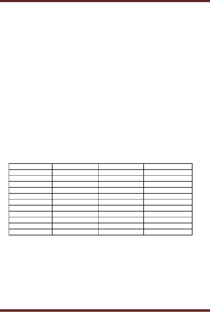
The table 1.1 indicates
that the Caveman numbers
Ć↑ represents
decimal number
9.
Decimal
Number
Caveman
Number
Decimal
Number
Caveman
Number
0
∑
10
>∑
1
Ć
11
>Ć
2
>
12
>>
3
Ω
13
>Ω
4
↑
14
>↑
5
Ć∑
15
Ω∑
6
ĆĆ
16
ΩĆ
7
Ć>
17
Ω>
8
ĆΩ
18
ΩΩ
9
Ć↑
19
Ω↑
20
↑∑
Table
1.1
Decimal
equivalents of the Caveman
Numbers
The
Caveman is using a Base-5
number system. A Base-5
number system has
five
unique
symbols representing numbers 0 to 4. To
represent numbers larger
than 4, a
combination of
2, 3, 4 or more combinations of Caveman
numbers are used. Therefore,
to
represent
the decimal number 5, a two
number combination of the
Caveman number system
is
used.
The most significant digit
is Ć
which is
equivalent to decimal 1. The
least significant
digit
is ∑ which is
equivalent to decimal 0. The
five combinations of Caveman
numbers having the
most
significant digit Ć, represent
decimal values 5 to 9 respectively.
This is similar to
the
Decimal
Number system, where a
2-digit combination of numbers is
used to represent
values
11
CS302 -
Digital Logic & Design
greater
than 9. The most significant
digit is set to 1 and the
least significant digit
varies from 0
to 9 to
represent the next 10 values
after the largest single
decimal number digit
9.
The
Caveman number Ć↑ can be
written in expression form
based on the Base value
5
and
weights 50, 51, 52 etc.
= Ć x 51 + ↑
x 50 = Ć
x 5 +
↑ x 1
Replacing
the Caveman numbers Ć and ↑ with
equivalent decimal values in
the expression
yields
= Ć x 51 + ↑
x 50 = 1 x 5 + 4 x 1 = 9
The
number ĆΩ↑∑
in
decimal is represented in expression
form as
Ć x 53 + Ω
x 52 + ↑
x 51 + ∑
x 50 = Ć
x
125 + Ω x 25 + ↑ x 5 + ∑ x 1
Replacing
the Caveman numbers with
equivalent decimal values in
the expression yields
= (1) x
125 + (3) x 25 + (4) x 5 +
(0) x 1 = 125 + 75 + 20 + 0 =
220
Binary
Number System
The
Caveman Number system is a
hypothetical number system
introduced to explain
that
number system other than
the Decimal Number system
can exist and can be
used to
represent
and count numbers. Digital
systems use a Binary number
system. Binary as the
name
indicates is a Base-2 number
system having only two
numbers 0 and 1. The Binary
digit
0 or 1 is known
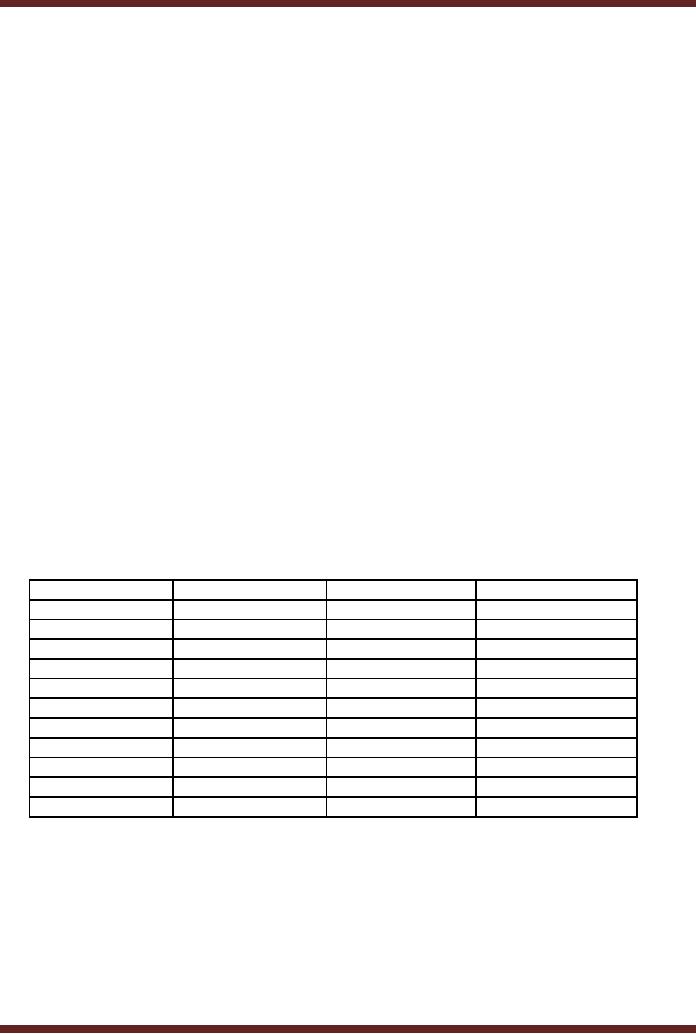
as a `Bit'. Table 1.2
Decimal
Number
Binary
Number
Decimal
Number
Binary
Number
0
0
10
1010
1
1
11
1011
2
10
12
1100
3
11
13
1101
4
100
14
1110
5
101
15
1111
6
110
16
10000
7
111
17
10001
8
1000
18
10010
9
1001
19
10011
20
10100
Table
1.2
Decimal
equivalents of Binary Number
System
Counting in
Binary Number system is
similar to counting in Decimal or
Caveman
Number
systems. In a decimal Number
system a value larger than 9
has to be represented by
2, 3, 4 or more
digits. In the Caveman
Number System a value larger
than 4 has to be
represented by
2, 3, 4 or more digits of the
Caveman Number System.
Similarly, in the
Binary
Number
System a Binary number
larger than 1 has to be
represented by 2, 3, 4 or more
binary
digits.
12

CS302 -
Digital Logic & Design
Any binary
number comprising of Binary 0
and 1 can be easily
represented in terms of
its
decimal equivalent by writing
the Binary Number in the
form of an expression using
the
Base
value 2 and weights 20, 21, 22 etc.
The
number 100112 (the subscript 2 indicates
that the number is a binary
number and
not a
decimal number ten thousand
and eleven) can be rewritten
in terms of the
expression
100112 = (1 x 24) + (0 x
23) + (0 x 22) + (1 x 21) + (1 x
20)
= (1 x 16) + (0
x 8) + (0 x 4) + (1 x 2) + (1 x 1)
= 16 + 0 + 0 + 2 +
1
= 19
Fractions in
Binary Number
System
In a Decimal
number system the Integer
part and the Fraction
part of a number are
separated by a
decimal point. In a Binary
Number System the Integer
part and the
Fraction
part of a
Binary Number can be
similarly represented separated by a
decimal point. The
Binary
number
1011.1012
has an
Integer part represented by
1011 and a fraction part
101 separated
by a decimal
point. The subscript 2
indicates that the number is
a binary number and not
a
decimal
number. The Binary number
1011.1012
can be
written in terms of an expression
using
the
Base value 2 and weights
23, 22, 21, 20, 2-1, 2-2 and 2-3.
1011.1012 = (1 x 23) + (0 x
22) + (1 x 21) + (1 x 20) + (1 x
2-1) + (0 x 2-2) + (1 x 2-3)
= (1 x 8) + (0 x 4) + (1 x 2)
+ (1 x 1) + (1 x 1/2) + (0 x 1/4) + (1 x
1/8)
= 8 + 0 + 2 + 1 +
0.5 + 0 + 0.125
=
11.625
Computers do
handle numbers such as
11.625 that have an integer
part and a fraction
part.
However, it does not use
the binary representation
1011.101. Such numbers
are
represented
and used in Floating-Point
Numbers notation which will
be discussed latter.
13
Table of Contents:
- AN OVERVIEW & NUMBER SYSTEMS
- Binary to Decimal to Binary conversion, Binary Arithmetic, 1s & 2s complement
- Range of Numbers and Overflow, Floating-Point, Hexadecimal Numbers
- Octal Numbers, Octal to Binary Decimal to Octal Conversion
- LOGIC GATES: AND Gate, OR Gate, NOT Gate, NAND Gate
- AND OR NAND XOR XNOR Gate Implementation and Applications
- DC Supply Voltage, TTL Logic Levels, Noise Margin, Power Dissipation
- Boolean Addition, Multiplication, Commutative Law, Associative Law, Distributive Law, Demorgans Theorems
- Simplification of Boolean Expression, Standard POS form, Minterms and Maxterms
- KARNAUGH MAP, Mapping a non-standard SOP Expression
- Converting between POS and SOP using the K-map
- COMPARATOR: Quine-McCluskey Simplification Method
- ODD-PRIME NUMBER DETECTOR, Combinational Circuit Implementation
- IMPLEMENTATION OF AN ODD-PARITY GENERATOR CIRCUIT
- BCD ADDER: 2-digit BCD Adder, A 4-bit Adder Subtracter Unit
- 16-BIT ALU, MSI 4-bit Comparator, Decoders
- BCD to 7-Segment Decoder, Decimal-to-BCD Encoder
- 2-INPUT 4-BIT MULTIPLEXER, 8, 16-Input Multiplexer, Logic Function Generator
- Applications of Demultiplexer, PROM, PLA, PAL, GAL
- OLMC Combinational Mode, Tri-State Buffers, The GAL16V8, Introduction to ABEL
- OLMC for GAL16V8, Tri-state Buffer and OLMC output pin
- Implementation of Quad MUX, Latches and Flip-Flops
- APPLICATION OF S-R LATCH, Edge-Triggered D Flip-Flop, J-K Flip-flop
- Data Storage using D-flip-flop, Synchronizing Asynchronous inputs using D flip-flop
- Dual Positive-Edge triggered D flip-flop, J-K flip-flop, Master-Slave Flip-Flops
- THE 555 TIMER: Race Conditions, Asynchronous, Ripple Counters
- Down Counter with truncated sequence, 4-bit Synchronous Decade Counter
- Mod-n Synchronous Counter, Cascading Counters, Up-Down Counter
- Integrated Circuit Up Down Decade Counter Design and Applications
- DIGITAL CLOCK: Clocked Synchronous State Machines
- NEXT-STATE TABLE: Flip-flop Transition Table, Karnaugh Maps
- D FLIP-FLOP BASED IMPLEMENTATION
- Moore Machine State Diagram, Mealy Machine State Diagram, Karnaugh Maps
- SHIFT REGISTERS: Serial In/Shift Left,Right/Serial Out Operation
- APPLICATIONS OF SHIFT REGISTERS: Serial-to-Parallel Converter
- Elevator Control System: Elevator State Diagram, State Table, Input and Output Signals, Input Latches
- Traffic Signal Control System: Switching of Traffic Lights, Inputs and Outputs, State Machine
- Traffic Signal Control System: EQUATION DEFINITION
- Memory Organization, Capacity, Density, Signals and Basic Operations, Read, Write, Address, data Signals
- Memory Read, Write Cycle, Synchronous Burst SRAM, Dynamic RAM
- Burst, Distributed Refresh, Types of DRAMs, ROM Read-Only Memory, Mask ROM
- First In-First Out (FIFO) Memory
- LAST IN-FIRST OUT (LIFO) MEMORY
- THE LOGIC BLOCK: Analogue to Digital Conversion, Logic Element, Look-Up Table
- SUCCESSIVE APPROXIMATION ANALOGUE TO DIGITAL CONVERTER