 |
CS302 -
Digital Logic & Design
Lesson
No. 38
EQUATION
DEFINITION
The
Equation definition for the
Traffic Controller defines
the TRSTATE variable
dependent
upon the clock transition.
The Timer is reset when
the state is either NSY2
or
Equations
TRSTATE.CLK =
clk;
TMRST :=
(TRSTATE = = NSY2) # (TRSTATE = =
EWY2);
EWY2.
Table 38.1.
Table
38.1
Equation
definition for the Traffic
Light Controller
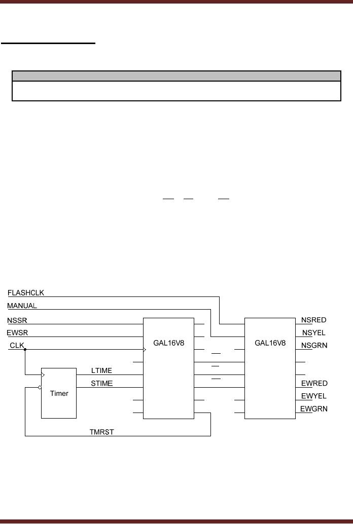
The
circuit diagram of the Timer
connected to the GAL16V8
based Traffic Light
Controller is
shown. Figure 38.1. The
first GAL16V8 is connected to
the external inputs
NSSR,
EWSR
and the CLK signal. It is
also connected to the two
Timer signals LTIME and
STIME
which
determine the Green cycle
time of the controller
during the day and
night respectively.
The
output of the controller is
the TMRST which resets
the Timer when the
Controller is in
state
NSY2 or EWY2. The state
outputs Q0 , Q1 and Q2 are
the inverted state
outputs,
which
determine the current state
and are also connected to
the input of the second
GAL16V8
which is
programmed for a combinational
circuit to turn on/off the
North-South and
East-West
road
section traffic signal
lights NSRED, NSYEL, NSGRN,
EWRED, EWYEL and
EWGRN.
The
chip is also connected to
the MANUAL and FLASHCLK
inputs. The MANUAL input
when
activated
puts the traffic signal in
the Manual Mode where
the Yellow signal on the
North-
South
and the East-West road
section repeatedly flashes.
The flash rate is determined
by the
FLASHCLK
signal.
Q0
Q1
Q2
Figure
38.1
The
circuit diagram of the
Traffic Light
Controller
Switching of
Traffic Lights
The
main definitions and
declaration of the ABEL
Input file for turning
on/off the traffic
lights is
given. Table 38.2. The
Pin Declarations are defined
in Table 38.2a. The
MANUAL
input
signal when activated
switches the traffic signal
to the manula mode and
flashes the
385
CS302 -
Digital Logic & Design
Yellow
lamps. The flash rate is
determined by the frequency of
the input signal connected
at
the
FLASHCLK input pin. The
appropriate lamp is turned
on/off on the basis of the
Traffic
Controller
States which are determined
by the Q0 , Q1 and Q2 inputs.
The outputs NSRED,
NSYEL,
NSGRN, EWRED, EWYEL and
EWGRN represent the outputs
that are connected to
the
traffic signal lamps.
Pin
Declarations
FLASHCLK,
MANUAL
pin 1,
2;
!Q0,
!Q1, !Q2
pin 4, 5,
6;
NSRED,
NSYEL, NSGRN
pin
19, 18, 17;
EWRED,
EWYEL, EWGRN
pin
14, 13, 12;
Table
38.2a
Pin
declarations for the turning
on/off traffic lamps
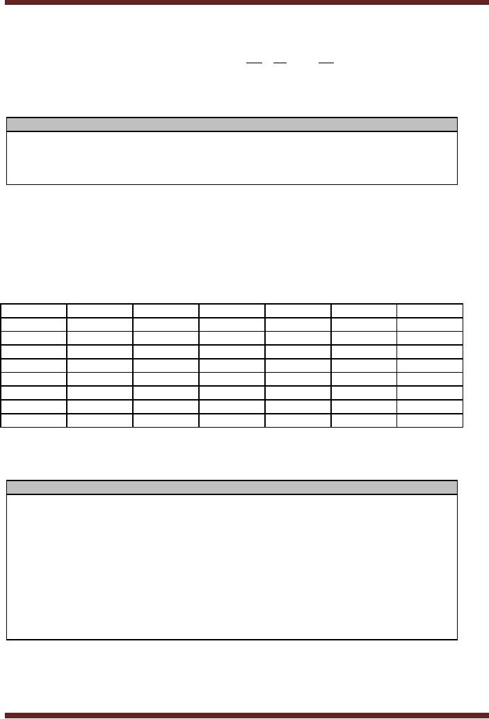
The
Red, Yellow and Green
signals that are turned
on/off at different states
are shown.
Table
38.2b. The equations
defining the six outputs
that turn on the Red,
Yellow and Green
signals on
the North-South and the
East-West road section are
defined. Table 38.2c.
When
the MANUAL
signal is set the NSYEL
and EWYEL outputs are
set to logic high and
low
depending
upon the input signal
FLASHCLK.
State
NSGRN
NSYEL
NSRED
EWGRN
EWYEL
EWRED
NSG
on
off
off
off
off
on
NSY
off
on
off
off
off
on
NSY2
off
on
off
off
off
on
NSR
off
off
on
off
off
on
EWG
off
off
on
on
off
off
EWY
off
off
on
off
on
off
EWY2
off
off
on
off
on
off
EWR
off
off
on
off
off
on
Table
38.2b
Switching of
traffic lamps at different
states
Equations
NSRED =
!MANUAL & (TRSTATE !=NSG) &
(TRSTATE != NSY)
& (TRSTATE
!= NSY2);
NSYEL =
!MANUAL & ((TRSTATE = = NSY) #
(TRSTATE = = NSY2))
# MANUAL &
FLASHCLK;
NSGRN =
!MANUAL & (TRSTATE = =
NSG);
EWRED =
!MANUAL & (TRSTATE !=EWG) &
(TRSTATE != EWY)
& (TRSTATE
!= EWY2);
EWYEL =
!MANUAL & ((TRSTATE = = EWY) #
(TRSTATE = = EWY2))
# MANUAL &
FLASHCLK;
EWGRN =
!MANUAL & (TRSTATE = =
EWG);
Table
38.2c
Equation
definition for the turning
on/off traffic lamps
386
CS302 -
Digital Logic & Design
Analysis of
Clocked Synchronous State
Machines
Analysis of
Clocked Synchronous State
Machine is opposite to the
Design and
Implementation
procedure studied. In the
analysis procedure an implemented
State Machine
is described in
terms of a state table or a
state diagram which
specifies all the next
states
outputs
for all possibilities of the
current state and input.
The analysis of a
clocked
Synchronous
state machine has three
basic steps.
· Determine
the next-state output
functions F and G
o Next
State = F(Current State,
Input)
o Output =
G(Current State,
Input)
· Use
the functions F and G to
construct a state/output
table
· Draw a
State diagram that
represents the information in
graphical form
The
functional behaviour of a flip-flop or a
latch is described by a
characteristic
equation
that is a function of its
current state and inputs.
The characteristic equation
does not
take
into account the exact
timing behaviour; it simply
describes the functional
response.
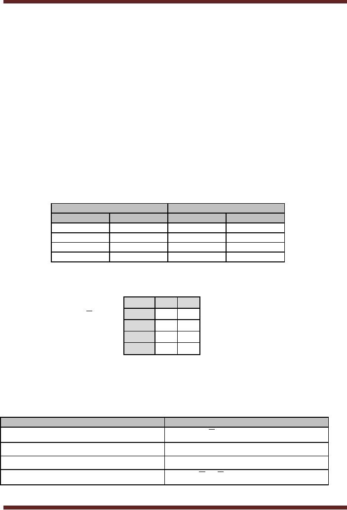
These
characteristic equations can be
derived from the excitation
tables discussed earlier.
The
excitation
table for an S-R latch is
shown. Table 38.3. The
information in the table is
mapped
to a
three-variable Karnaugh map to
derive the Characteristic
equation. Figure
38.2.
Flip-flop
Inputs
Output
Transitions
S
R
Qt
Qt+1
0
x
0
0
1
0
0
1
0
1
1
0
x
0
1
1
Table
38.3
S-R
flip-flop Transition
table
SR/Qt
0
1
00
0
1
Q t+1 = S + RQ t
01
0
0
11
x
x
10
1
1
Figure
38.2
Characteristic
Equation for S-R
Latch
The
characteristic equations for
other flip-flops and latches
can be derived
similarly.
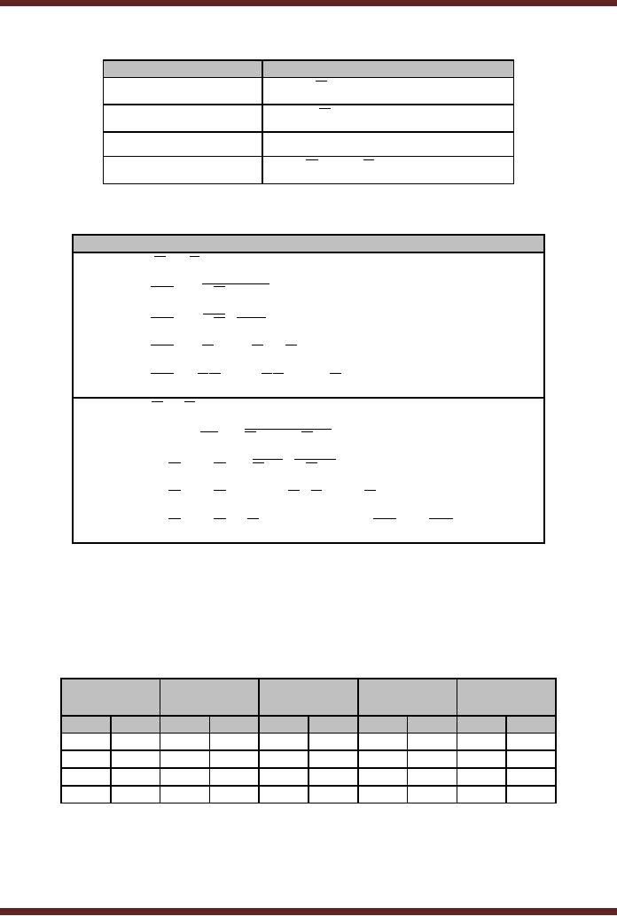
Characteristic
equations for some of the
flip-flops or latches discussed so
far are listed in
table
38.4.
Device
Type
Characteristic
Equation
S-R
Latch
Q t+1 = S + RQ t
D
Latch
Q t+1 = D
Edge-triggered D
flip-flop
Q t+1 = D
J-K
flip-flop
Q t+1 = JQ t + KQ t
Table
38.4
Characteristic
equations of Latches and
Flip-flops
387
CS302 -
Digital Logic & Design
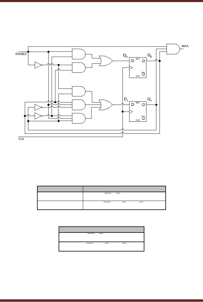
Two
examples of Synchronous State
machines are
described.
State
Machine Analysis
Example1:
A State
Machine with two
positive-edge triggered D flip-flops is
shown. Figure 38.3.
Figure
38.3
Clocked
Synchronous State Machine
based on D flip-flops
The
two flip-flops transfer
their D input values to
their respective outputs,
based on the
Characteristic
equation for the
D-flip-flop. The excitation
inputs to the two D
flip-flops are
determined by
the combinational circuit
shown. The two excitation
equations for D0 and
D1
inputs
are given. Table 38.5.
The two Transition equations
for the inputs D0 and D1
are
given.
Table
38.6.
D Flip-flop
Inputs
Excitation
Inputs
D0
D = Q EN + Q EN
0
0
0
D1
D1 = Q1EN + Q 0 Q1EN + Q 0Q1EN
Table
38.5
Excitation
Equations for D flip-flop
inputs D0
and D1
Transition
Equations
Q 0( t+1) = Q 0 EN + Q 0EN
Q1( t+1) = Q1EN + Q 0 Q1EN + Q 0Q1EN
Table
38.6
Transition
Equations for D
flip-flops
In the
State Machine, two D
flip-flops are used and
the outputs Q0 and
Q1 represent the
state
variables.
Two State variables allow a
maximum of four states. From
the Transition
equations
a transition
table can be prepared. The
Transition Table is shown.
Table 38.7.
388
CS302 -
Digital Logic & Design
Present
Next
State
Next
State
State
ENABLE=0
ENABLE=1
Q1
Q0
Q1
Q0
Q1
Q0
0
0
0
0
0
1
0
1
0
1
1
0
1
0
1
0
1
1
1
1
1
1
0
0
Table
38.7
Transition
Table for D flip-flop based
State Machine
The
Transition table is very
similar to the State table.
The state table can be
derived from the
Transition
table by assigning State
Names to each State and
including the output of the
State
Machine.
The output of the State
Machine is determined by the
Output Equation
MAX = Q 0Q1EN
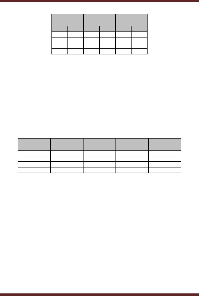
The
State Table for a Mealy
Machine is given. Table
38.8. The Transition Table
represents the
function of
the Mealy State Machine
which is a 2-bit Counter.
The Counter doesn't count
when
the
input ENABLE=0 and
increments when input
ENABLE=1. The output MAX of
the State
Machine is
dependent upon the current
state and the Input
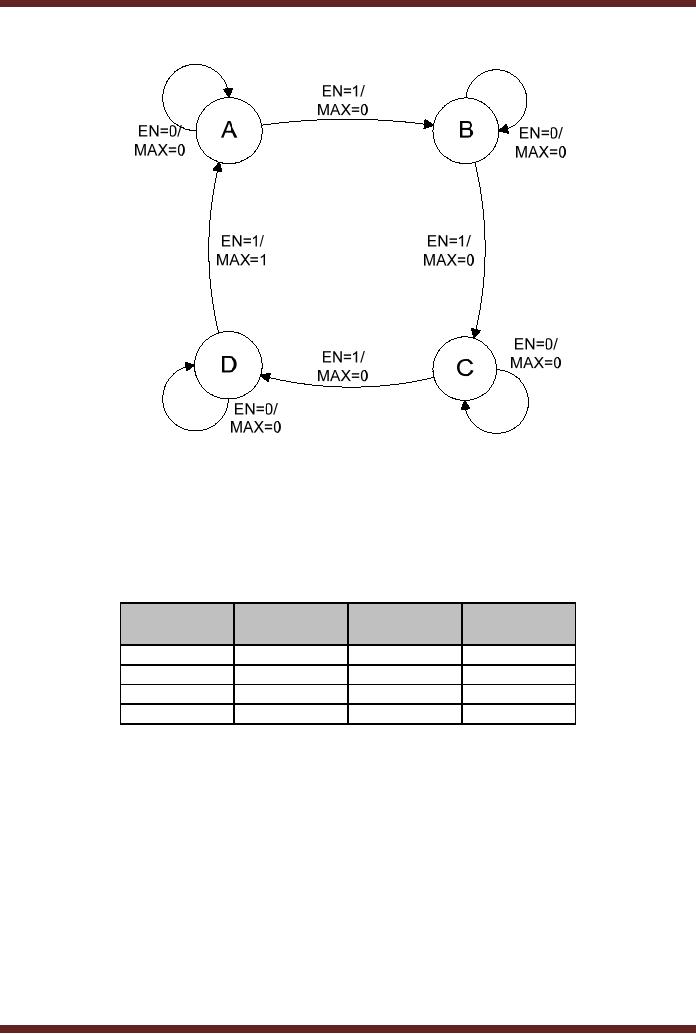
ENABLE. The State Diagrams
for
the
Mealy State machine derived
from the State Table is
shown. Figure 38.4.
Present
Next
State
Next
State
Output
MAX
Output
MAX
State
ENABLE=0
ENABLE=1
ENABLE=0
ENABLE=1
A
A
B
0
0
B
B
C
0
0
C
C
D
0
0
D
D
A
0
1
Table
38.8
State
table of a Mealy
Machine
389
CS302 -
Digital Logic & Design
Figure
38.4
State
Diagram of a Mealy
Machine
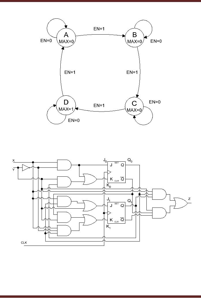
In the
circuit diagram of the State
machine if the output was
independent of the external
input
and
only dependent upon the
current state of the
flip-flops, then the
resulting machine is a
Moore
Machine with a simplified
State Table. Table 38.9
and State diagram. Figure
38.5.
Present
Next
State
Next
State
Output
MAX
State
ENABLE=0
ENABLE=1
A
A
B
0
B
B
C
0
C
C
D
0
D
D
A
1
Table
38.9
State
table of a Moore
Machine
390
CS302 -
Digital Logic & Design
Figure
38.5
State
Diagram of a Moore
Machine
State
Machine Analysis
Example2:
A State
Machine with two edge
triggered J-K flip-flops is
shown. Figure 38.6
Figure
38.6
Clocked
Synchronous State Machine
based on J-K
flip-flops
The
two flip-flops Set/Reset
their respective Q outputs
based on the J-K input
defined by the
Characteristic
equation for the
J-K-flip-flop. The excitation
inputs to the two J-K
flip-flops are
determined by
the combinational circuit
shown. The two sets of
excitation equations for J0 K0
and
J1 K1 inputs are given.
Table 38.10. The Transition
equations for the inputs
J0 K0 and
J1 K1
are
given. Table 38.11.
391
CS302 -
Digital Logic & Design
J-K
Flip-flop Inputs
Excitation
Inputs
J0
J0 = XY
K0
K 0 = XY + Q1Y
J1
J1 = XQ0 + Y
K1
K 1 = Q 0 Y + XYQ 0
Table
38.10
Excitation
Equations for J-K flip-flop
inputs J0
K0 and J1
K1
Transition
Equations
Q 0( t+1) = J0 Q 0 + K 0Q 0
Q 0( t+1) = XYQ 0 + ( XY + Q1Y)Q 0
Q 0( t+1) = XYQ 0 + ( XY)(Q1Y)Q 0
Q 0( t+1) = XYQ 0 + ( X + Y)(Q1 + Y)Q 0
Q 0( t+1) = XYQ 0 + XQ1Q 0 + XYQ 0 + YQ1Q 0
Q1( t+1) = J1 Q1 + K 1Q1
Q1( t+1) = ( XQ0 + Y)Q1 + (Q 0 Y + XYQ 0 )Q1
Q1( t+1) = XQ0 Q1 + YQ1 + (Q 0 Y)( XYQ 0 )Q1
Q1( t+1) = XQ0 Q1 + YQ1 + (Q 0 + Y)( X + Y + Q 0 )Q1
Q1( t+1) = XQ0 Q1 + YQ1 + XQ 0Q1 + YQ0Q1 + XYQ1 + YQ 0Q1
Table
38.11
Transition
Equations for J-K
flip-flops
In the
State Machine, two J-K
flip-flops are used and
the outputs Q0 and
Q1 represent the
state
variables.
Two State variables allow a
maximum of four states. The
present state changes
to
the
next state depending upon
external inputs X and Y.
From the Transition
equations a
transition
table can be prepared. The
Transition Table is shown.
Table 38.12.
Present
Next
State
Next
State
Next
State
Next
State
State
XY=00
XY=01
XY=10
XY=11
Q1
Q0
Q1
Q0
Q1
Q0
Q1
Q0
Q1
Q0
0
0
0
0
1
0
0
1
1
0
0
1
0
1
1
1
1
0
1
1
1
0
1
0
0
0
1
1
0
0
1
1
1
1
1
0
0
0
1
0
Table
38.12 Transition Table
for D flip-flop based State
Machine
The
Transition table is very
similar to the State table.
The state table can be
derived from the
Transition
table by assigning State
Names to each State and
including the output of the
State
Machine.
The output of the State
Machine is determined by the
Output Equation
392
CS302 -
Digital Logic & Design
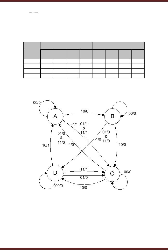
Z = XQ0Q1 + YQ 0 Q1
The
State Table for a Mealy
Machine is given. Table
38.13. The State Diagram
for the Mealy
State
machine derived from the
State Table is shown. Figure
38.7.
Presen
Next
State
Output
Z
t
State
XY
XY
XY
XY
XY
XY
XY
XY
00
01
10
11
00
01
10
11
A
A
C
B
C
0
1
0
1
B
B
D
C
D
0
0
0
0
C
C
A
D
A
0
0
0
0
D
D
C
A
C
0
0
1
1
Table
38.13
State
Table of a Mealy
Machine
Figure
38.7
State
Diagram of a Mealy
Machine
393
Table of Contents:
- AN OVERVIEW & NUMBER SYSTEMS
- Binary to Decimal to Binary conversion, Binary Arithmetic, 1s & 2s complement
- Range of Numbers and Overflow, Floating-Point, Hexadecimal Numbers
- Octal Numbers, Octal to Binary Decimal to Octal Conversion
- LOGIC GATES: AND Gate, OR Gate, NOT Gate, NAND Gate
- AND OR NAND XOR XNOR Gate Implementation and Applications
- DC Supply Voltage, TTL Logic Levels, Noise Margin, Power Dissipation
- Boolean Addition, Multiplication, Commutative Law, Associative Law, Distributive Law, Demorgans Theorems
- Simplification of Boolean Expression, Standard POS form, Minterms and Maxterms
- KARNAUGH MAP, Mapping a non-standard SOP Expression
- Converting between POS and SOP using the K-map
- COMPARATOR: Quine-McCluskey Simplification Method
- ODD-PRIME NUMBER DETECTOR, Combinational Circuit Implementation
- IMPLEMENTATION OF AN ODD-PARITY GENERATOR CIRCUIT
- BCD ADDER: 2-digit BCD Adder, A 4-bit Adder Subtracter Unit
- 16-BIT ALU, MSI 4-bit Comparator, Decoders
- BCD to 7-Segment Decoder, Decimal-to-BCD Encoder
- 2-INPUT 4-BIT MULTIPLEXER, 8, 16-Input Multiplexer, Logic Function Generator
- Applications of Demultiplexer, PROM, PLA, PAL, GAL
- OLMC Combinational Mode, Tri-State Buffers, The GAL16V8, Introduction to ABEL
- OLMC for GAL16V8, Tri-state Buffer and OLMC output pin
- Implementation of Quad MUX, Latches and Flip-Flops
- APPLICATION OF S-R LATCH, Edge-Triggered D Flip-Flop, J-K Flip-flop
- Data Storage using D-flip-flop, Synchronizing Asynchronous inputs using D flip-flop
- Dual Positive-Edge triggered D flip-flop, J-K flip-flop, Master-Slave Flip-Flops
- THE 555 TIMER: Race Conditions, Asynchronous, Ripple Counters
- Down Counter with truncated sequence, 4-bit Synchronous Decade Counter
- Mod-n Synchronous Counter, Cascading Counters, Up-Down Counter
- Integrated Circuit Up Down Decade Counter Design and Applications
- DIGITAL CLOCK: Clocked Synchronous State Machines
- NEXT-STATE TABLE: Flip-flop Transition Table, Karnaugh Maps
- D FLIP-FLOP BASED IMPLEMENTATION
- Moore Machine State Diagram, Mealy Machine State Diagram, Karnaugh Maps
- SHIFT REGISTERS: Serial In/Shift Left,Right/Serial Out Operation
- APPLICATIONS OF SHIFT REGISTERS: Serial-to-Parallel Converter
- Elevator Control System: Elevator State Diagram, State Table, Input and Output Signals, Input Latches
- Traffic Signal Control System: Switching of Traffic Lights, Inputs and Outputs, State Machine
- Traffic Signal Control System: EQUATION DEFINITION
- Memory Organization, Capacity, Density, Signals and Basic Operations, Read, Write, Address, data Signals
- Memory Read, Write Cycle, Synchronous Burst SRAM, Dynamic RAM
- Burst, Distributed Refresh, Types of DRAMs, ROM Read-Only Memory, Mask ROM
- First In-First Out (FIFO) Memory
- LAST IN-FIRST OUT (LIFO) MEMORY
- THE LOGIC BLOCK: Analogue to Digital Conversion, Logic Element, Look-Up Table
- SUCCESSIVE APPROXIMATION ANALOGUE TO DIGITAL CONVERTER