 |
Thinking Process for ISA Design |
| << RTL to Describe the SRC, Register Transfer using Digital Logic Circuits |
| Introduction to the ISA of the FALCON-A and Examples >> |

Advanced Computer
Architecture-CS501
Lecture
Handout
Computer
Architecture
Lecture
No. 7
Reading
Material
Hnadouts
Slides
Summary
8)
Outline of the thinking
process for ISA
Design
9)
Introduction to the ISA of
FALCON-A
Instruction
Set Architecture (ISA)
Design: Outline of the
thinking
process
In this
module we will learn to appreciate,
understand and apply the approach
adopted in
designing
an instruction set architecture. We do
this by designing an ISA for
a new
processor. We
have named our processor
FALCON-A, which is an acronym
for First
Architecture
for Learning Computer
Organization and Networks (version
A). The term
Organization
is intended to include Architecture and
Design in this
acronym.
Elements of
the ISA
Before we
go onto designing the
instruction set architecture
for our processor
FALCON-
A, we
need to take a closer look at
the defining components of an
ISA. The following
three
key components define any
instruction set
architecture.
1. The
operations the processor can
execute
2. Data
access mode for use as
operands in the operations
defined
3.
Representation of the operations in
memory
We take a
look at all three of the
components in more detail, and
wherever appropriate,
apply
these steps to the design of
our sample processor, the FALCON-A.
This will help
us better
understand the approach to be adopted
for the ISA design of a processor.
A
more
detailed introduction to the
FALCON-A will be presented
later.
The
operations the processor can
execute
All
processors need to support at least
three categories (or
functional groups) of
instructions
Arithmetic, Logic,
Shift
Data
Transfer
Control
Page
86
Last
Modified: 01-Nov-06

Advanced Computer
Architecture-CS501
ISA Design
Steps Step 1
We need
to think of all the
instructions of each type
that ought to be supported by
our
processor,
the FALCON-A. The following
are the instructions that we
will include in the
ISA
for our processor.
Arithmetic:
add, addi
(and with an immediate
operand), subtract,
subtract-immediate,
multiply,
divide
Logic:
and,
and-immediate, or, or-immediate,
not
Shift:
shift
left, shift right,
arithmetic shift
right
Data
Transfer:
Data
transfer between registers, moving
constants to registers, load operands
from
memory to
registers, store from registers to memory and
the movement of data
between
registers and
input/output devices
Control:
Jump
instructions with various
conditions, call and return
from subroutines,
instructions
for handling
interrupts
Miscellaneous
instructions:
Instructions
to clear all registers, the
capability to stop the processor, ability
to
"do
nothing", etc.
ISA Design
Steps Step 2
Once we
have decided on the
instructions that we want to
add support for in
our
processor,
the second step of the
ISA design process is to select suitable
mnemonics for
these
instructions. The following
mnemonics have been selected
to represent these
operations.
Arithmetic:
add,
addi, sub ,subi ,mul
,div
Logic:
and,
andi, or, ori,
not
Shift:
shiftl,
shiftr, asr
Data
Transfer:
load,
store, in, out, mov,
movi
Control:
jpl,
jmi, jnz, jz, jump,
call, ret, int.iret
Miscellaneous
instructions:
nop,
reset, halt
ISA Design
Steps Step 3
The
next step of the ISA design
is to decide upon the number
of bits to be reserved for
the
op-code part of the instructions. Since
we have 32 instructions in the
instruction set, 5
bits will
suffice (as 25 =32)
to encode these op-codes.
ISA Design
Steps Step 4
The
fourth step is to assign
op-codes to these instructions.
The assigned op-codes
are
shown
below.
Page
87
Last
Modified: 01-Nov-06
Advanced Computer
Architecture-CS501
Arithmetic:
add
(0), addi (1), sub (2), subi
(3), mul (4),div
(5)
Logic:
and (8),
andi (9), or (10), ori
(11), not (14)
Shift:
shiftl
(12), shiftr (13), asr
(15)
Data
Transfer:
load
(29), store (28), in (24),
out (25), mov (6),
movi (7)
Control:
jpl
(16), jmi (17), jnz
(18), jz (19), jump (20),
call (22), ret (23),
int (26), iret
(27)
Miscellaneous
instructions:
nop
(21), reset (30), halt
(31)
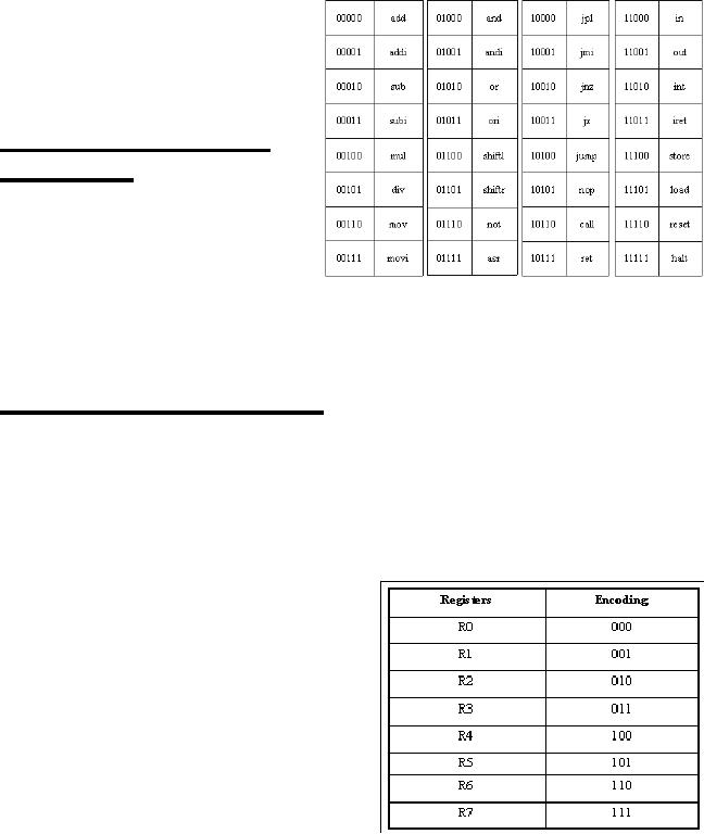
Now we list these
instructions with
their
op-codes in the binary form,
as
they
would appear in the
machine
instructions
of the FALCON-A.
Data
access mode for
operations
As
mentioned earlier, the
instruction
set
architecture of a processor
defines
a number
of things besides the
instructions
implemented; the
resources
each instruction can
access,
the
number of registers available to the
processor, the number of registers
each
instruction
can access, the instructions
that are allowed to access
memory, any special
registers,
constants and any alternatives to
the general-purpose registers. With
this in
mind, we
go on to the next steps of
our ISA design.
ISA Design
Steps Step 5
We now
need to select the number and
types of operands for
various instructions that
we
have
selected for the FALCON-A
ISA.
ALU
instructions may have 2 to 3 registers as
operands. In case of 2 operands, a
constant
(an
immediate operand) may be
included in the
instruction.
For
the load/store type
instructions, we require a register to
hold the data that is to
be
loaded
from the memory, or stored back to
the memory. Another register
is required to
hold
the base address for
the memory access. In
addition to these two registers, a
field is
required
in the instruction to specify
the
constant
that is the displacement to
the base
address.
In jump
instructions; we require a field
for
specifying
the register that holds
the value that
is to be compared as
the condition for
the
branch,
as well as a destination address,
which
is
specified as a constant.
Once we
have decided on the number
and
types of
operands that will be required in
each
of the
instruction types, we need to
address the
Page
88
Last
Modified: 01-Nov-06
Advanced Computer
Architecture-CS501
issue of
assigning specific bit-fields in
the instruction for each of
these operands. The
number of
bits required to represent each of
these operands will eventually
determine the
instruction
word size. In our example
processor, the FALCON-A, we reserve
eight
general-purpose
registers. To encode a register in the
instructions, 3 bits are
required (as
23 =8). The registers are
encoded in the binary as
shown in the given
table.
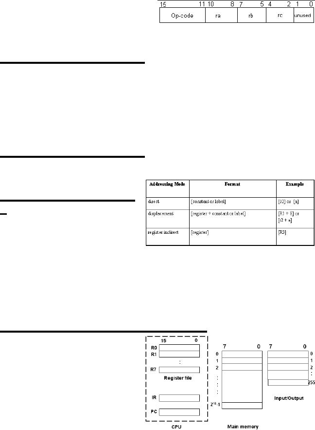
Therefore,
the instructions that we will
add support for FALCON-A
processor will have
the
given general format. The
instructions
in the
FALCON-A processor are going
to
be
variations of this format,
with four
different
formats in all. The exact
format is dependent on the actual
number of operands
in a
particular instruction.
ISA Design
Steps Step 6
The
next step towards completely
defining the instruction set
architecture of our
processor
is the design of memory and its
organization. The number of
the memory cells
that we
may have in the organization
depends on the size of the
Program Counter
register
(PC), and
the size of the address bus.
This is because the size of
the program counter
and
the size
of the address bus put a
limitation on the number of
memory cells that can
be
referred
to for loading an instruction
for execution. Additionally,
the size of the data
bus
puts a
limitation on the size of the
memory word that can be
referred to in a single
clock
cycle.
ISA Design
Steps Step 7
Now we
need to specify which
instructions will be allowed to access
the memory. Since
the
FALCON-A is intended to be a RISC-like
machine, only the load/
store instructions
will be
allowed to access the
memory.
ISA Design
Steps Step
8
Next we
need to select the
memory-
addressing
modes. The given table
lists
the
types of addressing modes
that will
be
supported for the
load/store
instructions.
FALCON-A:
Introduction
FALCON
stands for First
Architecture for Learning
Computer Organization and
Networks.
It is a `RISC-like' general-purpose
processor that will be used as a
teaching
aid for
this course. Although the
FALCON-A is a simple machine, it is
powerful enough
to
explain a variety of fundamental concepts
in the field of Computer
Architecture .
Programmer's
view of the
FALCON-A
FALCON-A,
an example of a GPR
(General
Purpose Register)
computer,
is the
first version of the
FALCON
processor.
The programmer's view
of
the
FALCON-A is given in the
figure
shown. As
it is clear from the
figure,
the
CPU contains a register file
of 8
registers, named R0
through R7. Each
of these
registers is 16 bits in length.
Page
89
Last
Modified: 01-Nov-06
Advanced Computer
Architecture-CS501
Aside
from these registers, there
are two special-purpose registers, the
Program Counter
(PC), and
the Instruction Register
(IR). The main memory is
organized as 216
x 8 bits,
i.e.
216 cells of 1 byte each.
The memory word size is 2
bytes (or 16 bits). The
input/output
space is
256 bytes (8 bit I/O ports).
The storage in these registers and
memory is in the
big-endian
format.
Page
90
Last
Modified: 01-Nov-06
Table of Contents:
- Computer Architecture, Organization and Design
- Foundations of Computer Architecture, RISC and CISC
- Measures of Performance SRC Features and Instruction Formats
- ISA, Instruction Formats, Coding and Hand Assembly
- Reverse Assembly, SRC in the form of RTL
- RTL to Describe the SRC, Register Transfer using Digital Logic Circuits
- Thinking Process for ISA Design
- Introduction to the ISA of the FALCON-A and Examples
- Behavioral Register Transfer Language for FALCON-A, The EAGLE
- The FALCON-E, Instruction Set Architecture Comparison
- CISC microprocessor:The Motorola MC68000, RISC Architecture:The SPARC
- Design Process, Uni-Bus implementation for the SRC, Structural RTL for the SRC instructions
- Structural RTL Description of the SRC and FALCON-A
- External FALCON-A CPU Interface
- Logic Design for the Uni-bus SRC, Control Signals Generation in SRC
- Control Unit, 2-Bus Implementation of the SRC Data Path
- 3-bus implementation for the SRC, Machine Exceptions, Reset
- SRC Exception Processing Mechanism, Pipelining, Pipeline Design
- Adapting SRC instructions for Pipelined, Control Signals
- SRC, RTL, Data Dependence Distance, Forwarding, Compiler Solution to Hazards
- Data Forwarding Hardware, Superscalar, VLIW Architecture
- Microprogramming, General Microcoded Controller, Horizontal and Vertical Schemes
- I/O Subsystems, Components, Memory Mapped vs Isolated, Serial and Parallel Transfers
- Designing Parallel Input Output Ports, SAD, NUXI, Address Decoder , Delay Interval
- Designing a Parallel Input Port, Memory Mapped Input Output Ports, wrap around, Data Bus Multiplexing
- Programmed Input Output for FALCON-A and SRC
- Programmed Input Output Driver for SRC, Input Output
- Comparison of Interrupt driven Input Output and Polling
- Preparing source files for FALSIM, FALCON-A assembly language techniques
- Nested Interrupts, Interrupt Mask, DMA
- Direct Memory Access - DMA
- Semiconductor Memory vs Hard Disk, Mechanical Delays and Flash Memory
- Hard Drive Technologies
- Arithmetic Logic Shift Unit - ALSU, Radix Conversion, Fixed Point Numbers
- Overflow, Implementations of the adder, Unsigned and Signed Multiplication
- NxN Crossbar Design for Barrel Rotator, IEEE Floating-Point, Addition, Subtraction, Multiplication, Division
- CPU to Memory Interface, Static RAM, One two Dimensional Memory Cells, Matrix and Tree Decoders
- Memory Modules, Read Only Memory, ROM, Cache
- Cache Organization and Functions, Cache Controller Logic, Cache Strategies
- Virtual Memory Organization
- DRAM, Pipelining, Pre-charging and Parallelism, Hit Rate and Miss Rate, Access Time, Cache
- Performance of I/O Subsystems, Server Utilization, Asynchronous I/O and operating system
- Difference between distributed computing and computer networks
- Physical Media, Shared Medium, Switched Medium, Network Topologies, Seven-layer OSI Model