 |
SRC, RTL, Data Dependence Distance, Forwarding, Compiler Solution to Hazards |
| << Adapting SRC instructions for Pipelined, Control Signals |
| Data Forwarding Hardware, Superscalar, VLIW Architecture >> |
Advanced Computer
Architecture-CS501
Advanced
Computer Architecture
Lecture
No. 20
Reading
Material
Vincent
P. Heuring & Harry F. Jordan
Chapter
5
Computer
Systems Design and Architecture
5.1.5,
5.1.6
Summary
·
Structural
RTL for Pipeline
Stages
·
Instruction
Propagation Through the
Pipeline
·
Pipeline
Hazards
·
Data
Dependence Distance
·
Data
Forwarding
·
Compiler
Solution to Hazards
·
SRC
Hazard Detection and
Correction
·
RTL for
Hazard Detection and Pipeline
Stall
Structural
RTL for Pipeline
Stages
The
Register Transfer Language
for each phase is given as
follows:
Instruction
Fetch
IR2
←
M
[PC];
PC2
←
PC+4;
Instruction
Decode & Operand fetch
X3←l-s2:(rel2:PC2,disp2:(rb=0):?,(rb!=0):R[rb]),brl2:PC2,alu2:R[rb],
Y3 ← l-s2:(rel2:c1,disp2:c2),alu2:(imm2:c2,!imm2:R[rc]),
MD3
←store2:R[ra],IR3
←
IR2,stop2:Run
←
0,
PC ← !branch2:PC+4,branch2:(cond(IR2,R[rc]):R[rb],!cond(IR2,R[rc]):PC+4;
ALU
operation
Z4 ← (I-s3:
X3+Y3, brl3: X3, Alu3: X3 op
Y3,
MD4
←
MD3,
IR4
←
IR3;
Memory
access
Z5 ← (load4: M
[Z4], ladr4~branch4~alu4:Z4),
store4:
(M [Z4] ← MD4),
Page
214
Last
Modified: 01-Nov-06
Advanced Computer
Architecture-CS501
IR5
←IR4;
Write
back
regwrite5:
(R[ra] ← Z5);
Instruction
Propagation through the
Pipeline
Consider
the following SRC code segment
flowing through the
pipeline. The
instructions
along
with their addresses
are
200: add
r1, r2, r3
204: ld
r5, [4(r7)
208: br
r6
212:
str r4, 56
...
400
We shall
review how this chunk of
code is executed.
First
Clock Cycle
Add
instruction enters the pipeline in
the first cycle. The
value in PC is
incremented
from 200 to 204.
Second
Clock Cycle
Add
moves to decode stage. Its
operands are fetched from
the register file and
moved to
X3 and Y3 at the end of clock cycle,
meanwhile the Instruction ld
r5,
[4+r7] is
fetched in the first stage
and the PC value is incremented
from 204 to
208.
Third
Clock Cycle
Add
instruction moves to the
execute stage, the results
are written to Z4 on
the
trailing
edge of the clock. Ld
instruction moves to decode
stage. The operands
are
fetched to calculate the
displacement address. Br instruction
enters the
pipeline.
The value in PC is incremented
from 208 to 212.
Fourth
Clock Cycle
Add
does not access memory.
The result is written to Z5 at
the trailing edge of
clock.
The address is being
calculated here for ld. The
results are written to
Z4.
Br is in
the decode stage. Since this
branch is always true, the
contents of PC are
modified
to new address. Str
instruction enters the pipeline.
The value in PC is
incremented
from 212 to 216.
Fifth
Clock Cycle
Page
215
Last
Modified: 01-Nov-06
Advanced Computer
Architecture-CS501
The
result of addition is written
into register r1. Add
instruction completes. Ld
accesses
data memory at the address
specified in Z4 and result stored in Z5
at
falling
edge of clock. Br instruction
just propagates through this
stage without
any
calculation. Str is in the
decode stage. The operands
are being fetched
for
address
calculation to X3 and Y3. The instruction
at address 400 enters the
pipeline.
The value in PC is incremented
from 400 to 404.
Pipeline
Hazards
The
instructions in the pipeline at
any given time are
being executed in parallel.
This
parallel
execution leads to the
problem of instruction dependence. A
hazard occurs when
an
instruction depends on the
result of previous instruction
that is not yet
complete.
Classification of
Hazards
There
are three categories of
hazards
1. Branch
Hazard
2.
Structural Hazard
3. Data
Hazard
Branch
hazards
The
instruction following a branch is
always executed whether or
not the branch is
taken.
This is
called the branch delay
slot. The compiler might
issue a nop instruction in
the
branch
delay slot. Branch delays
cannot be avoided by forwarding
schemes.
Structural
hazards
Page
216
Last
Modified: 01-Nov-06
Advanced Computer
Architecture-CS501
A
structural hazard occurs
when attempting to access
the same resource in different
ways
at the
same time. It occurs when
the hardware is not enough
to implement pipelining
properly
e.g. when the machine does
not support separate data
and instruction memories.
Data
hazards
Data
hazard occur when an
instruction attempts to access
some data value that
has not yet
been
updated by the previous instruction. An
example of this RAW (read after
write) data
hazard
is;
200:
add r2, r3, r4
204: sub
r7, r2, r6
The
register r2 is written in clock
cycle 5 hence the sub instruction
cannot proceed
beyond
stage 2 until the add
instruction leaves the
pipeline.
Data
Hazard Detection &
Correction
Data hazards can be
detected easily as they
occur when the destination
register of an
instruction
is the same as the source
register of another instruction in close
proximity. To
remedy
this situation, dependent instructions
may be delayed or stalled
until the ones
ahead
complete. Data can also be forwarded to
the next instruction before
the current
instruction
completes, however this
requires forwarding hardware and
logic. Data can be
forwarded
to the next instruction from
the stage where it is
available without waiting
for
the
completion of the instruction. Data is
normally required at stage 2
(operand fetch)
however
data is earliest available at
stage 3 output (ALU result) or
stage 4 output
(memory
access result). Hence the
forwarding logic should be able to
transfer data from
stage 3
to stage 2 or from stage 4 to
stage 2.
Data
Dependence Distance
Designing
a data forwarding unit
requires the study of
dependence distances. Without
forwarding,
the minimum spacing required
between two data dependent
instructions to
avoid
hazard is four. The load
instruction has a minimum distance of
two from all
other
instructions
except branch. Branch delays
cannot be removed even with
forwarding.
Table
5.1 of the text shows
numbers related to dependence
distances with respect to
some
important
instruction categories.
Compiler
Solution to Hazards
Hazards
can be detected by the compiler, by
analyzing the instruction
sequences and
dependencies.
The compiler can inserts
bubbles (nop instruction)
between two
instructions
that form a hazard, or it
could reorder instructions so as to
put sufficient
distance
between dependent instructions. The
compiler solution to hazards is
complex,
expensive
and not very efficient as compared to
the hardware solution
Page
217
Last
Modified: 01-Nov-06
Advanced Computer
Architecture-CS501
SRC
Hazard Detection and
Correction
The SRC
uses a hazard detection
unit. The hazard can be
resolved using either
pipeline
stalls or
by data forwarding.
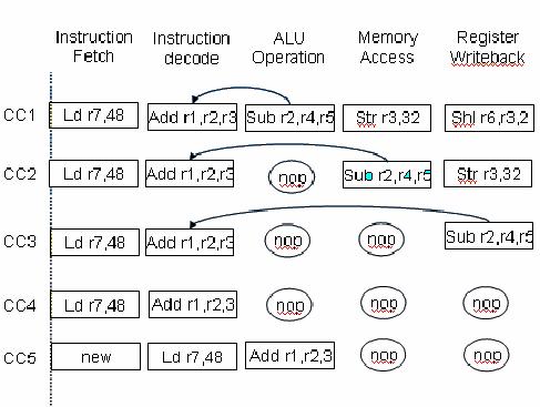
Pipeline
stalls
Consider
the following sequence of
instructions going
through
the SRC pipeline
200:
shl r6, r3, 2
204:
str r3, 32
208: sub
r2, r4,r5
212:
add r1,r2,r3
216: ld
r7, 48
There is
a data hazard between
instruction three and
four
that can
be resolved by using pipeline
stalls or bubbles
When
using pipeline stalls, nop
instructions are placed in between
dependent instructions.
The
logic behind this scheme is
that if opcode in stage 2 and 3
are both alu, and if ra
in
stage 3
is the same as rb or rc in stage 2,
then a pause signal is
issued to insert a
bubble
between
stage 3 and 2. Similar logic is
used for detecting hazards
between stage 2 and 4
and stage
4 and 5.
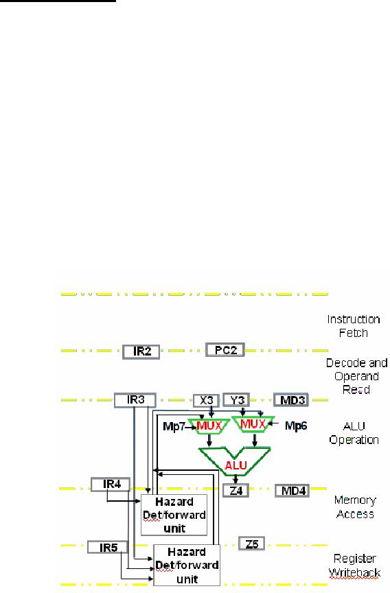
Data
Forwarding
By adding
data forwarding mechanism to
the SRC data path, the
stalls can be completely
eliminated
at least for the ALU instructions.
The hazard detection is
required between
stages 3
and 4, and between stages 3 and 5. The
testing and forwarding circuits
employ
wider
IRs to store the data
required in later stages.
The logic behind this
method is that if
the ALU
is activated for both 3 and 5 and ra in 5
is the same as rb in 3 then Z5
which
hold
the currently loaded or calculated
result is directly forwarded to
X3. Similarly, if
both
are ALU operations and instruction in
stage 3 does not employ
immediate operands
then
value of Z5 is transferred to Y3. Similar
logic is used to forward
data between stage
3 and
4.
RTL
for Hazard Detection and
Pipeline Stall
The
following RTL expression detects
data hazard between stage 2
and 3, then stalls
stage 1
and 2 by inserting a bubble in stage
3
alu3&alu2&((ra3=rb2)~((ra3=rc2)&!imm2)):
(pause2,
pause1, op3←0)
Meaning:
If opcode
in stage 2 and 3 are both ALU, and if ra
in stage 3 is same as rb or rc in stage
2,
issue a
pause signal to insert a
bubble between stage 3 and
2
Page
218
Last
Modified: 01-Nov-06
Advanced Computer
Architecture-CS501
Following
is the complete RTL for
detecting hazards among ALU instructions
in
different
stages of the
pipeline
Data
Hazard
RTL
for detection and
stalling
between
Stage 2
and 3
alu3&alu2&((ra3=rb2)~((ra3=rc2)&!imm2)):
(pause2,
pause1, op3←0)
Stage 2
and 4
alu4&alu2&((ra4=rb2)~((ra4=rc2)&!imm2)):
(pause2,
pause1, op3←0)
Stage 2
and 5
alu5&alu2&((ra5=rb2)~((ra5=rc2)&!imm2)):
(pause2,
pause1, op3←0)
Page
219
Last
Modified: 01-Nov-06
Advanced Computer
Architecture-CS501
Advanced
Computer Architecture
Lecture
21
Reading
Material
Vincent
P. Heuring&Harry F. Jordan
Chapter
5
Computer
Systems Design and Architecture
5.2
Summary
·
Data
Forwarding Hardware
·
Instruction
Level Parallelism
·
Difference
between Pipelining and Instruction-Level
Parallelism
·
Superscalar
Architecture
·
Superscalar
Design
·
VLIW
Architecture
Maximum
Distance between two
instructions
Example
Read
page no. 219 of Computer
System Design and Architecture
(Vincent
P.Heuring,
Harry F. Jordan)
Data
forwarding Hardware
The
concept of data forwarding was
introduced in the previous
lecture.
RTL
for
data
Page
220
Last
Modified: 01-Nov-06
Table of Contents:
- Computer Architecture, Organization and Design
- Foundations of Computer Architecture, RISC and CISC
- Measures of Performance SRC Features and Instruction Formats
- ISA, Instruction Formats, Coding and Hand Assembly
- Reverse Assembly, SRC in the form of RTL
- RTL to Describe the SRC, Register Transfer using Digital Logic Circuits
- Thinking Process for ISA Design
- Introduction to the ISA of the FALCON-A and Examples
- Behavioral Register Transfer Language for FALCON-A, The EAGLE
- The FALCON-E, Instruction Set Architecture Comparison
- CISC microprocessor:The Motorola MC68000, RISC Architecture:The SPARC
- Design Process, Uni-Bus implementation for the SRC, Structural RTL for the SRC instructions
- Structural RTL Description of the SRC and FALCON-A
- External FALCON-A CPU Interface
- Logic Design for the Uni-bus SRC, Control Signals Generation in SRC
- Control Unit, 2-Bus Implementation of the SRC Data Path
- 3-bus implementation for the SRC, Machine Exceptions, Reset
- SRC Exception Processing Mechanism, Pipelining, Pipeline Design
- Adapting SRC instructions for Pipelined, Control Signals
- SRC, RTL, Data Dependence Distance, Forwarding, Compiler Solution to Hazards
- Data Forwarding Hardware, Superscalar, VLIW Architecture
- Microprogramming, General Microcoded Controller, Horizontal and Vertical Schemes
- I/O Subsystems, Components, Memory Mapped vs Isolated, Serial and Parallel Transfers
- Designing Parallel Input Output Ports, SAD, NUXI, Address Decoder , Delay Interval
- Designing a Parallel Input Port, Memory Mapped Input Output Ports, wrap around, Data Bus Multiplexing
- Programmed Input Output for FALCON-A and SRC
- Programmed Input Output Driver for SRC, Input Output
- Comparison of Interrupt driven Input Output and Polling
- Preparing source files for FALSIM, FALCON-A assembly language techniques
- Nested Interrupts, Interrupt Mask, DMA
- Direct Memory Access - DMA
- Semiconductor Memory vs Hard Disk, Mechanical Delays and Flash Memory
- Hard Drive Technologies
- Arithmetic Logic Shift Unit - ALSU, Radix Conversion, Fixed Point Numbers
- Overflow, Implementations of the adder, Unsigned and Signed Multiplication
- NxN Crossbar Design for Barrel Rotator, IEEE Floating-Point, Addition, Subtraction, Multiplication, Division
- CPU to Memory Interface, Static RAM, One two Dimensional Memory Cells, Matrix and Tree Decoders
- Memory Modules, Read Only Memory, ROM, Cache
- Cache Organization and Functions, Cache Controller Logic, Cache Strategies
- Virtual Memory Organization
- DRAM, Pipelining, Pre-charging and Parallelism, Hit Rate and Miss Rate, Access Time, Cache
- Performance of I/O Subsystems, Server Utilization, Asynchronous I/O and operating system
- Difference between distributed computing and computer networks
- Physical Media, Shared Medium, Switched Medium, Network Topologies, Seven-layer OSI Model