 |
Reverse Assembly, SRC in the form of RTL |
| << ISA, Instruction Formats, Coding and Hand Assembly |
| RTL to Describe the SRC, Register Transfer using Digital Logic Circuits >> |
Advanced Computer
Architecture-CS501
Lecture
Handout
Computer
Architecture
Lecture
No. 5
Reading
Material
Handouts
Slides
Summary
1) Reverse
Assembly
2)
Description of SRC in the form of
RTL
3)
Behavioral and Structural description in
terms of RTL
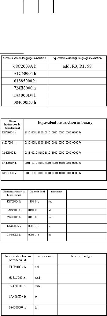
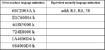
Reverse
Assembly
Typical
Problem:
Given a
machine language instruction
for the SRC, it may be
required to find the
equivalent
SRC assembly language
instruction
Example:
Reverse
assemble the following SRC
machine language
instructions:
68C2003A
h
E1C60004
h
61885000
h
724E8000
h
1A4000D4
h
084000D0
h
Solution:
1. Write
the given hexadecimal
instruction in binary
form
68C2003A
h →
0110 1000
1100 0010 0000 0000 0011 1010 b
2.
Examine the first five
bits of the instruction, and
pick the corresponding
mnemonic
from
the SRC instruction set
listing arranged according to ascending
order of op-codes
01101 b → 13 d → addi → add
immediate
3. Now we
know that this instruction
uses the type C format,
the two 5-bit fields
after the
op-code
field represent the destination and
the source registers respectively, and
that the
remaining
17-bits in the instruction represent a
constant
Page
62
Last
Modified: 01-Nov-06
Advanced Computer
Architecture-CS501
0110 1000 1100 0010
0000 0000 0011 1010 b
op-code
ra field rb field
17-bit c1
field
↓
↓
↓
↓
addi
R3
R1
3A h=58
d
4.
Therefore, the assembly
language instruction is
addi R3,
R1, 58
Summary
We can do it a
bit faster now! Step1:
Here is
step1 for all
instructions
Step
2: Pick up
the op code for each
instruction
Step
3: Determine
the instruction type for
each instruction
Page
63
Last
Modified: 01-Nov-06
Advanced Computer
Architecture-CS501
The
meaning of the remaining
fields will depend on the
instruction type (i.e.,
the
instruction
format)
Summary
Note:Rest
of the fields of above given
tables are left as an
exercise for
students.
Using
RTL to describe the
SRC
RTL
stands for Register Transfer
Language. The Register
Transfer Language provides
a
formal
way for the description of
the behavior and structure of a
computer. The RTL
facilitates
the design process of the
computer as it provides a precise,
mathematical
representation
of its functionality. In this
section, a Register Transfer
Language is
presented
and introduced, for the SRC
(Simple `RISC' Computer),
described in the
previous
discussion.
Behavioral
RTL
Behavioral
RTL is used to describe the
`functionality' of the machine
only, i.e. what
the
machine
does.
Structural
RTL
Structural
RTL describes the `hardware
implementation' of the machine,
i.e. how the
functionality
made available by the
machine is implemented.
Behavioral
versus Structural
RTL:
In
computer design, a top-down approach is adopted.
The computer design
process
typically
starts with defining the
behavior of the overall
system. This is then broken
down
into
the behavior of the
different modules. The
process continues, till we
are able to
define,
design and implement the structure of
the individual modules.
Behavioral RTL is
used
for describing the behavior
of machine whereas structural RTL is used
to define the
structure
of machine, which brings us to
the some more hardware
features.
Using
RTL to describe the static properties of the
SRC
In this
section we introduce the RTL by
using it to describe the
various static
properties
of the
SRC.
Specifying
Registers
The
format used to specify registers
is
Register
Name<register bits>
For
example, IR<31..0> means
bits numbered 31 to 0 of a 32-bit
register named "IR"
(Instruction
Register).
"Naming"
using the := naming
operator:
Page
64
Last
Modified: 01-Nov-06
Advanced Computer
Architecture-CS501
The
:=
operator
is used to `name' registers, or part of
registers, in the Register
Transfer
Language.
It does not create a new
register; it just generates
another name, or "alias"
for
an
already existing register or
part of a register. For
example,
Op<4..0>:
= IR<31..27> means that
the five most significant
bits of the register IR
will
be called
op, with bits
4..0.
Fields in the
SRC instruction
In this
section, we examine the
various fields of an SRC instruction,
using the RTL.
op<4..0>:
= IR<31..27>; operation code
field
The
five most significant bits
of an SRC instruction, (stored in the
instruction register in
this
example), are named op, and
this field is used for
specifying the
operation.
ra<4..0>:
= IR<26..22>;
target
register field
The
next five bits of the SRC
instruction, bits 26 through
22, are used to hold
the address
of the
target register field, i.e.,
the result of the operation
performed by the instruction
is
stored in
the register specified by
this field.
rb<4..0>:
= IR<21..17>;
operand,
address index, or branch
target register
The
bits 21 through 17 of the
instruction are used for
the rb field. rb field is
used to hold
an operand, an
address index, or a branch
target register.
rc<4..0>:
= IR<16..12>;
second
operand, conditional test, or shift
count register
The
bits 16 through 12, are
the rc field. This field
may hold the second
operand,
conditional
test, or a shift
count.
c1<21..0>:
= IR<21..0>; long
displacement field
In some
instructions, the bits 21
through 0 may be used as
long displacement
field.
Notice
that there is an overlap of
fields. The fields are
distinguished in a particular
instruction
depending on the
operation.
c2<16..0>:
= IR<16..0>; short
displacement or immediate
field
The
bits 16 through 0 may be
used as short displacement or to
specify an immediate
operand.
c3<11..0>:
= IR<11..0>; count or
modifier field
The
bits 11 through 0 of the SRC
instruction may be used for
count or modifier
field.
Describing the
processor state using
RTL
The
Register Transfer Language can be
used to describe the
processor state. The
following
registers and bits together form
the processor state
set.
PC<31..0>;
program
counter (it holds the
memory address of
next
instruction
to be executed)
IR<31..0>;
instruction
register, used to hold the
current instruction
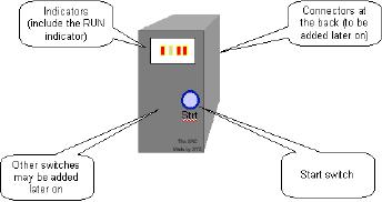
Run;
one bit
run/halt indicator
Strt;
start
signal
R
[0..31]<31..0>; 32, 32 bit
general purpose registers
SRC in a
Black Box
Page
65
Last
Modified: 01-Nov-06
Advanced Computer
Architecture-CS501
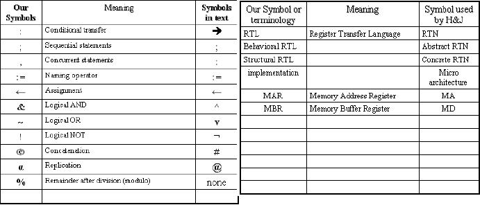
Difference
between our notation and
notation used by the text
(H&J)
Difference
between "," and ";" in
RTL
Statements
separated by a "," take place during the
same clock pulse. In other
words, the
order of
execution of statements separated by ","
does
not matter.
On the
other hand, statements separated by a
";"
take
place on successive clock pulses.
In
other
words, if statements are separated by
";"
the one
on the left must complete
before
the one
on the right starts. However,
some things written with one
RTL statement can
take
several clocks to
complete.
So in the
instruction interpretation, fetch-execute
cycle, we can see that the
first
statement.
! Run & Strt : Run ← 1, executes
first. After this statement
has executed and
set
run to 1, the statements IR ← M [PC]
and PC ←
PC + 4
are executed
concurrently.
Note
that in statements separated by ",",
all right hand sides of
Register Transfers
are
evaluated
before any left hand
side is modified (generally
though assignment).
Using
RTL to describe the dynamic properties of
the SRC
The RTL
can be used to describe the
dynamic properties.
Conditional
expressions can be specified through the
use of RTL. The following
example
will
illustrate this
(op=14) :
R [ra] ← R [rb] -
R[rc];
The
←
operator
is the RTL assignment operator. `;' is
the termination operator.
This
conditional
expression implies that "IF
the op field is equal to 14,
THEN calculate the
difference
of the value in the register
specified by the rb field and
the value in the
register
specified
by the rc field, and store the
result in the register
specified by the ra
field."
Effective
address calculations in RTL (performed at
runtime)
Page
66
Last
Modified: 01-Nov-06
Advanced Computer
Architecture-CS501
In some
instructions, the address of an operand
or the destination register
may not be
specified
directly. Instead, the
effective address may have
to be calculated at runtime.
These
effective address calculations can be
represented in RTL, as illustrated
through the
examples
below.
Displacement
address
disp<31..0>
:= ((rb=0) : c2<16..0> {sign
extend},
(rb≠0) : R
[rb] + c2<16..0> {sign
extend}),
The
displacement (or the direct)
address is being calculated in
this example. The ","
operator
separates statements in a single
instruction, and indicates that
these statements
are to be
executed simultaneously. However, since
in this example these are
two disjoint
conditions,
therefore, only one action will be
performed at one time.
Note
that register R0 cannot be
added to displacement. rb = 0 just
implies we do not
need
to use
the R [rb] field.
Relative
address
rel<31..0>
:= PC<31..0> + c1<21..0>
{sign extend},
In the
above example, a relative address is
being calculated by adding
the displacement
after
sign extension to the
contents of the program
counter register (that holds
the next
instruction
to be executed in a program execution
sequence).
Range
of memory addresses
The range
of memory addresses that can be
accessed using the
displacement (or the
direct)
addressing and the relative
addressing is given.
� Direct
addressing (displacement with
rb=0)
o If
c2<16>=0 (positive displacement)
absolute addresses range
from
00000000h
to 0000FFFFh
o If
c2<16>=1 (negative displacement)
absolute addresses range
from
FFFF0000h
to FFFFFFFFh
� Relative
addressing
o The
largest positive value of
C1<21..0> is 221-1 and
its most negative
value is
-221, so addresses up to
221-1 forward and 221 backward from
the
current
PC value can be specified
Instruction
Interpretation
(Describing
the Fetch operation using
RTL)
The
action performed for all
the instructions before they
are decoded is called
`instruction
interpretation'.
Here, an example is that of
starting the machine. If the
machine is not
already
running (�Run, or `not'
running), AND (&) it the condition
start (Strt) becomes
true,
then Run bit (of
the processor state) is set to 1
(i.e. true).
instruction_Fetch
:= (
!
Run & Strt: Run ← 1
;
instruction_Fetch
Run
: (IR ← M
[PC], PC ← PC +
4;
instruction_Execution
) );
The := is
the naming operator. The ;
operator is used to add
comments in RTL. The
,
operator,
specifies that the statements are to be
executed simultaneously, (i.e. in a
single
clock
pulse). The ; operator is
used to separate sequential statements.
←
is an
assignment
operator.
& is a logical AND, ~ is a logical
OR, and ! is the logical
NOT. In the
instruction
interpretation phase of the
fetch-execute cycle, if the
machine is running
(Run
Page
67
Last
Modified: 01-Nov-06
Advanced Computer
Architecture-CS501
is true),
the instruction register is loaded
with the instruction at the
location M [PC] (the
program
counter specifies the address of
the memory at which the
instruction to be
executed
is located). Simultaneously, the
program counter is incremented by 4, so
as to
point to
the next instruction, as
shown in the example above.
This completes the
instruction
interpretation.
Instruction
Execution
(Describing
the Execute operation using
RTL)
Once
the instruction is fetched and
the PC is incremented, execution of
the instruction
starts. In
the following, we denote instruction
Fetch by "iF" and instruction
execution by
"iE".
iE:=
(
(op<4..0>=
1) : R [ra] ← M
[disp],
(op<4..0>=
2) : R [ra] ← M
[rel],
...
...
(op<4..0>=31)
: Run ← 0,);
iF);
As shown
above, Instruction Execution can be
described by using a long
list of
conditional
operations, which are
inherently "disjoint".
One of
these statements is executed, depending
on the condition met, and
then the
instruction
fetch statement (iF) is
invoked again at the end of the
list of concurrent
statements.
Thus, instruction fetch (iF)
and instruction execution statements
invoke each
other in
a loop. This is the
fetch-execute cycle of the
SRC.
Concurrent
Statements
The
long list of concurrent,
disjoint instructions of the
instruction execution (iE)
is
basically
the complete instruction set
of the processor. A brief overview of
these
instructions
is given below.
Load-Store
Instructions
(op<4..0>=
1) : R [ra] ← M
[disp], load register
(ld)
This
instruction is to load a register
using a displacement address
specified by the
instruction,
i.e. the contents of the
memory at the address `disp'
are placed in the
register
R
[ra].
(op<4..0>=
2) : R [ra] ← M
[rel], load register relative
(ldr)
If the
operation field `op' of the
instruction decoded is 2, the
instruction that is
executed
is
loading a register (target
address of this register is
specified by the field ra)
with
memory
contents at a relative address,
`rel'. The relative address
calculation has been
explained
in this section
earlier.
(op<4..0>=
3) : M [disp] ← R
[ra], store register
(st)
If the
op-code is 3, the contents of the
register specified by address
ra, are stored back to
the
memory, at a displacement location
`disp'.
(op<4..0>=
4) : M[rel] ← R[ra],
store register relative
(str)
If the
op-code is 4, the contents of the
register specified by the
target register address
ra,
are
stored back to the memory, at a relative
address location
`rel'.
(op<4..0>=
5) : R [ra] ← disp,
load displacement
address (la)
For
op-code 5, the displacement address disp
is loaded to the register R (specified by
the
target
register address ra).
(op<4..0>=
6) : R [ra] ← rel,
load
relative address
(lar)
For
op-code 6, the relative address
rel is loaded to the register R
(specified by the
target
register
address ra).
Page
68
Last
Modified: 01-Nov-06
Advanced Computer
Architecture-CS501
Branch
Instructions
(op<4..0>=
8) : (cond : PC ← R
[rb]), conditional branch
(br)
If the
op-code is 8, a conditional branch is
taken, that is, the
program counter is set to
the
target
instruction address specified by
rb, if the condition `cond'
is true.
(op<4..0>=
9) : (R [ra] ← PC,
cond
: (PC ← R
[rb]) ), branch and link
(brl)
If the op
field is 9, branch and link
instruction is executed, i.e.
the contents of the
program
counter are stored in a register
specified by ra field, (so control can be
returned
to it
later), and then the
conditional branch is taken to a
branch target address
specified by
rb.
The branch and link
instruction is useful for
returning control to the
calling program
after a
procedure call
returns.
The
conditions that these
`conditional' branches depend on are
specified by the field
c3
that
has 3 bits. This simply
means that when
c3<2..0> is equal to one of these
six values.
We
substitute the expression on
the right hand side of
the : in place of cond
These
conditions are explained here
briefly.
cond
:= (
c3<2..0>=0
: 0,
never
If the c3
field is 0, the branch is
never taken.
c3<2..0>=1
: 1,
always
If the
field is 1, branch is
taken
c3<2..0>=2
: R [rc]=0,
if
register is zero
If c3 = 2, a
branch is taken if the
register rc = 0.
c3<2..0>=3
: R [rc] ≠ 0,
if
register is nonzero
If c3 = 3, a
branch is taken if the
register rc is not equal to
0.
c3<2..0>=4
: R [rc]<31>=0 if positive or
zero
If c3 is 4, a
branch is taken if the
register value in the
register specified
by rc is greater
than or equal to 0.
c3<2..0>=5
: R [rc]<31>=1), if
negative
If c3 = 5, a
branch is taken if the value
stored in the register specified
by
rc is
negative.
Arithmetic
and Logical instructions
(op<4..0>=12)
: R [ra] ← R
[rb] + R [rc],
If the
op-code is 12, the contents of
the registers rb and rc are added and
the result is
stored in
the register ra.
(op<4..0>=13)
: R [ra] ← R
[rb] + c2<16..0> {sign
extend},
If the
op-code is 13, the content of
the register rb is added
with the immediate data in
the
field
c2, and the result is stored in
the register ra.
(op<4..0>=14)
: R [ra] ← R
[rb] R [rc],
If the
op-code is 14, the content of
the register rc is subtracted from
that of rb, and the
result is
stored in ra.
(op<4..0>=15)
: R [ra] ← -R
[rc],
If the
op-code is 15, the content of
the register rc is negated, and the
result is stored in ra.
(op<4..0>=20)
: R [ra] ← R
[rb] & R [rc],
If the op
field equals 20, logical AND of
the contents of the registers rb and rc
is obtained
and the
result is stored in register
ra.
(op<4..0>=21)
: R [ra] ← R
[rb] & c2<16..0> {sign
extend},
If the op
field equals 21, logical AND of
the content of the registers rb and
the immediate
data in
the field c2 is obtained and
the result is stored in register
ra.
Page
69
Last
Modified: 01-Nov-06
Advanced Computer
Architecture-CS501
(op<4..0>=22)
: R [ra] ← R
[rb] ~ R [rc],
If the op
field equals 22, logical OR of
the contents of the registers rb and rc
is obtained
and the
result is stored in register
ra.
(op<4..0>=23)
: R [ra] ← R
[rb] ~ c2<16..0> {sign
extend},
If the op
field equals 23, logical OR of
the content of the registers rb and
the immediate
data in
the field c2 is obtained and
the result is stored in register
ra.
(op<4..0>=24)
: R [ra] ← �R
[rc],
If the
op-code equals 24, the content of
the logical NOT of the
register rc is obtained, and
the
result is stored in ra.
Shift
instructions
(op<4..0>=26):
R [ra]<31..0 > ← (n α 0) R
[rb] <31..n>,
If the
op-code is 26, the contents of
the register rb are shifted
right n bits times. The
bits
that
are shifted out of the
register are discarded. 0s are
added in their place, i.e. n
number
of 0s is
added (or concatenated) with
the register contents. The
result is copied to the
register
ra.
(op<4..0>=27)
: R [ra]<31..0 > ← (n α R
[rb] <31>) R [rb]
<31..n>,
For
op-code 27, shift arithmetic
operation is carried out. In
this operation, the contents
of
the
register rb are shifted
right n times, with the
most significant bit, bit
31, of the register
rb added
in their place. The result is copied to
the register ra.
(op<4..0>=28)
: R [ra]<31..0 > ← R
[rb] <31-n..0> (n α 0),
For
op-code 28, the contents of
the register rb are shifted
left n bits times, similar
to the
shift
right instruction. The
result is copied to the register
ra.
(op<4..0>=29)
: R [ra]<31..0 > ← R
[rb] <31-n..0> R [rb]<31..32-n
>,
The
instruction corresponding to op-code 29 is
the shift circular
instruction. The
contents
of the
register rb are shifted left
n times, however, the bits
that move out of the
register in
the
shift process are not
discarded; instead, these are shifted in
from the other end (a
circular
shifting). The result is stored in
register ra.
where
n :=
(
(c3<4..0>=0)
: R [rc],
(c3<4..0>!=0)
: c3 <4..0> ),
Notation:
α means
replication
Means concatenation
Miscellaneous
instructions
(op<4..0>=
0) ,
No
operation (nop)
If the
op-code is 0, no operation is carried out
for that clock period.
This instruction is
used as a
stall in pipelining.
(op<4..0>=
31) : Run ← 0,
Halt the processor
(Stop)
); iF
);
If the
op-code is 31, run is set to 0,
that is, the processor is
halted.
After one
of these disjoint instructions is
executed, iF, i.e.
instruction Fetch is carried
out
once again, and so
the fetch-execute
cycle
continues.
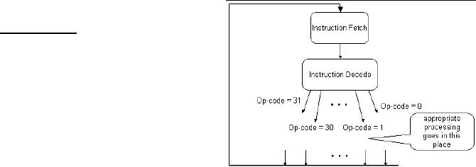
Flow
diagram
Flow
diagram
is
the
symbolic
representation
of Fetch-Execute cycle.
Its
top
block indicates instruction
fetch and
then
next block shows the
instruction
decode by
looking at the first 5-bits
of the
Page
70
Last
Modified: 01-Nov-06
Advanced Computer
Architecture-CS501
fetched
instruction which would represent op-code
which may be from 0
to
31.Depending
upon the contents of this
op-code the appropriate processing would
take
place.
After the appropriate processing, we
would move back to top
block, next
instruction
is fetched and the same
process is repeated until
the instruction with
op-code
31 would
reach and halt the
system.
Note:For
SRC Assembler and Simulator consult
Appendix.
Page
71
Last
Modified: 01-Nov-06
Table of Contents:
- Computer Architecture, Organization and Design
- Foundations of Computer Architecture, RISC and CISC
- Measures of Performance SRC Features and Instruction Formats
- ISA, Instruction Formats, Coding and Hand Assembly
- Reverse Assembly, SRC in the form of RTL
- RTL to Describe the SRC, Register Transfer using Digital Logic Circuits
- Thinking Process for ISA Design
- Introduction to the ISA of the FALCON-A and Examples
- Behavioral Register Transfer Language for FALCON-A, The EAGLE
- The FALCON-E, Instruction Set Architecture Comparison
- CISC microprocessor:The Motorola MC68000, RISC Architecture:The SPARC
- Design Process, Uni-Bus implementation for the SRC, Structural RTL for the SRC instructions
- Structural RTL Description of the SRC and FALCON-A
- External FALCON-A CPU Interface
- Logic Design for the Uni-bus SRC, Control Signals Generation in SRC
- Control Unit, 2-Bus Implementation of the SRC Data Path
- 3-bus implementation for the SRC, Machine Exceptions, Reset
- SRC Exception Processing Mechanism, Pipelining, Pipeline Design
- Adapting SRC instructions for Pipelined, Control Signals
- SRC, RTL, Data Dependence Distance, Forwarding, Compiler Solution to Hazards
- Data Forwarding Hardware, Superscalar, VLIW Architecture
- Microprogramming, General Microcoded Controller, Horizontal and Vertical Schemes
- I/O Subsystems, Components, Memory Mapped vs Isolated, Serial and Parallel Transfers
- Designing Parallel Input Output Ports, SAD, NUXI, Address Decoder , Delay Interval
- Designing a Parallel Input Port, Memory Mapped Input Output Ports, wrap around, Data Bus Multiplexing
- Programmed Input Output for FALCON-A and SRC
- Programmed Input Output Driver for SRC, Input Output
- Comparison of Interrupt driven Input Output and Polling
- Preparing source files for FALSIM, FALCON-A assembly language techniques
- Nested Interrupts, Interrupt Mask, DMA
- Direct Memory Access - DMA
- Semiconductor Memory vs Hard Disk, Mechanical Delays and Flash Memory
- Hard Drive Technologies
- Arithmetic Logic Shift Unit - ALSU, Radix Conversion, Fixed Point Numbers
- Overflow, Implementations of the adder, Unsigned and Signed Multiplication
- NxN Crossbar Design for Barrel Rotator, IEEE Floating-Point, Addition, Subtraction, Multiplication, Division
- CPU to Memory Interface, Static RAM, One two Dimensional Memory Cells, Matrix and Tree Decoders
- Memory Modules, Read Only Memory, ROM, Cache
- Cache Organization and Functions, Cache Controller Logic, Cache Strategies
- Virtual Memory Organization
- DRAM, Pipelining, Pre-charging and Parallelism, Hit Rate and Miss Rate, Access Time, Cache
- Performance of I/O Subsystems, Server Utilization, Asynchronous I/O and operating system
- Difference between distributed computing and computer networks
- Physical Media, Shared Medium, Switched Medium, Network Topologies, Seven-layer OSI Model