 |
Programmed Input Output Driver for SRC, Input Output |
| << Programmed Input Output for FALCON-A and SRC |
| Comparison of Interrupt driven Input Output and Polling >> |
Advanced Computer
Architecture-CS501
________________________________________________________
Advanced
Computer Architecture
Lecture
No. 27
Reading
Material
Vincent
P. Heuring & Harry F. Jordan
Chapter
8
Computer
Systems Design and Architecture
8.2.2
Summary
· Programmed
I/O Driver for SRC
· Interrupt
Driven I/O
Programmed
I/O Driver for
SRC
Please
refer to Figure 8.10 of the
text and its associated
explanation.
Interrupt
Driven I/O:
Introduction:
An
interrupt is a request to the CPU to
suspend normal processing and temporarily
divert
the
flow of control through a
new program. This new
program to which control
is
transferred
is called an Interrupt Service
Routine or ISR. Another name
for an ISR is an
Interrupt
Handler.
·
Interrupts
are used to demand attention
from the CPU.
·
Interrupts
are asynchronous breaks in
program flow that occur as a
result of events
outside
the running program.
·
Interrupts
are usually hardware
related, stemming from
events such as a key or
button
press,
timer expiration, or completion of a
data transfer.
Page
273
Last
Modified: 01-Nov-06
Advanced Computer
Architecture-CS501
________________________________________________________
The
basic purpose of interrupts
is to
divert CPU processing
only
when it
is required. As an
example
let us consider the
example
of a user typing a
document
on word-processing
software
running on a multi
tasking
operating system. It is
up to the
software to display a
character
when the user presses
a key on
the keyboard. To
fulfill
this
responsibility the
processor
can
repeatedly poll the keyboard
to check if the user has
pressed a key. However,
the
average
user can type at most 50 to 60 words in a
minute. The rate of input is
much
slower
than the speed of the
processor. Hence, most of the
polling messages that
the
processor
sends to the keyboard will be wasted. A
significant fraction of the
processor's
cycles
will be wasted checking for user input on
the keyboard. It should also be
kept in
mind
that there are usually
multiple peripheral devices such as
mouse, camera, LAN card,
modem,
etc. If the processor would
poll each and every one of
these devices for input,
it
would be
wasting a large amount of
its time. To solve this
problem, interrupts
are
integrated
into the system. Whenever a
peripheral device has data
to be exchanged with
the
processor, it interrupts the processor;
the processor saves its
state and then executes
an
interrupt handler routine
(which basically exchanges data
with the device). After
this
exchange
is completed, the processor
resumes its task. Coming
back to the keyboard
example,
if it takes the average user
approximately 500 ms to press consecutive
keys a
modern
processor like the Pentium
can execute up to 300,000,000
instructions in these
500 Ms.
Hence, interrupts are an
efficient way to handle I/O compared to
polling.
Advantages
of interrupts:
·
Useful for interfacing I/O devices
with low data transfer
rates.
·
CPU is not tied up in a
tight loop for polling
the I/O device.
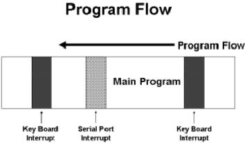
Program
Flow for an interrupt driven
interface:
The
attached figure shows the
program flow executing on a
processor with
interrupts
enabled. As we can
see, the program is
interrupted in several locations to
service various
types of
interrupts.
Types
of Interrupts:
The
general categories of interrupts
are as follows:
·
Internal Interrupts
·
External Interrupts
·
Hardware Interrupts
·
Software Interrupts
Internal
Interrupts:
·
Internal interrupts are
generated by the processor.
Page
274
Last
Modified: 01-Nov-06
Advanced Computer
Architecture-CS501
________________________________________________________
·
These are
used by processor to handle
the exceptions generated
during instruction
execution.
Internal
interrupts are generated to
handle conditions such as stack
overflow or a divide-
by-zero
exception. Internal interrupts
are also referred to as traps.
They are mostly
used
for
exception handling. These types of
interrupts are also called
exceptions and were
discussed
previously.
External
Interrupts:
External
interrupts are generated by
the devices other than the
processor. They are of
two
types.
·
Hardware interrupts are
generated by the external
hardware.
·
Software interrupts are
generated by the software
using some interrupt
instruction.
As the
name implies, external interrupts
are generated by devices external to
the CPU,
such as
the click of a mouse or pressing a key on
a keyboard. In most cases,
input from
external
sources requires immediate
attention. These events require a
quick service by the
software,
e.g., a word processing software
must quickly display on the
monitor, the
character
typed by the user on the
keyboard. A mouse click should
produce immediate
results.
Data received from the LAN card or
the modem must be copied
from the buffer
immediately
so that pending data is not
lost because of buffer
overflow, etc.
Hardware
interrupts:
Hardware
interrupts are generated by
external events specific to
peripheral devices. Most
processors
have at least one line dedicated to
interrupt requests. When a device
signals on
this
specific line, the processor
halts its activity and executes an
interrupt service
routine.
Such
interrupts are always
asynchronous with respect to
instruction execution, and
are
not
associated with any
particular instruction. They do
not prevent instruction
completion
as
exceptions like an arithmetic
overflows does. Thus, the
control unit only needs
to
check
for such interrupts at the
start of every new
instruction. Additionally, the
CPU
needs to
know the identification and
priority of the device
sending the interrupt
request.
There
are two types of hardware
interrupt:
Maskable
Interrupts
Non-maskable
Interrupts
Maskable
Interrupts:
· These
interrupts are applied to
the INTR pin of the
processor.
· These can be
blocked by resetting the
flag bit for the
interrupts.
Non-maskable
Interrupts:
· These
interrupts are detected
using the NMI pin of the
processor.
· These can
not be blocked or
masked.
· Reserved
for catastrophic event in
the system.
Software
interrupts:
Page
275
Last
Modified: 01-Nov-06
Advanced Computer
Architecture-CS501
________________________________________________________
Software
interrupts are usually
associated with the
software. A simple output
operation in
a
multitasking system requires
software interrupts to be generated so
that the processor
may
temporarily halt its
activity and place the data on
its data bus for the
peripheral
device.
Output is usually handled by
interrupts so that it appears
interactive and
asynchronous.
Notification of other events,
such as expiry of a software
timer is also
handled
by software interrupts. Software
interrupts are also used
with system calls.
When
the
operating system switches
from user mode to supervisor mode it does
so through
software
interrupts. Let us consider an
example where a user program
must delete a file.
The user
program will be executing in the user
mode. When it makes the
specific system
call to
delete the file, a software
interrupt will be generated, this will
cause the processor
to halt
its current activity (which
would be the user program) and
switch to supervisor
mode.
Once in supervisor mode, the
operating system will delete the
file and then control
will
return to the user program.
While in supervisor mode the
operating system
would
need to
decide if it could delete the
specified file with out
harmful consequences to
the
systems
integrity, hence it is important that
the system switch to
supervisor mode at each
system
call.
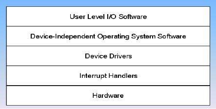
I/O
Software System
Layers:
The above
diagram shows the various
software layers related to
I/O. At the bottom
lies
the
actual hardware itself, i.e.
the peripheral device. The
peripheral device uses
the
hardware
interrupts to communicate with
the processor. The processor
responds by
executing
the interrupt handler for
that particular device. The
device drivers form
the
bridge
between the hardware and the
software. The operating
system uses the
device
drivers
to communicate with the
device in a hardware independent
fashion, e.g., the
operating
system need not cater for a
specific brand of CRT
monitors, or keyboards,
the
specific
device driver written for
that monitor or keyboard will act as an
intermediary
between
the operating system and the
device. It would be clear
from the previous
statement
that the operating system
expects certain common functions
from all brands of
devices in a
category. Actually implementing
these functions for each
particular brand or
vendor is
the responsibility of the
device driver. The user
programs run at top of
the
operating
system.
Interrupt
Service Routine
(ISR):
Page
276
Last
Modified: 01-Nov-06
Advanced Computer
Architecture-CS501
________________________________________________________
·
It is a
routine which is executed
when an interrupt
occurs.
·
Also
known as an Interrupt
Handler.
·
Deals
with low-level events in the
hardware of a computer system,
like a tick of a
real-time
clock.
As it was
mentioned earlier, an interrupt once
generated must be serviced
through an
interrupt
service routine. These routines
are stored in the system
memory ready for
execution.
Once the interrupt is generated,
the processor must branch to
the location of
the
appropriate service routine to execute
it. The branch address of
the ISR is discussed
next.
Branch
Address of the ISR:
There
are two ways used to
choose the branch address of
an Interrupt Service
Routine.
Non-vectored
Interrupts
Vectored
Interrupts
Non-vectored
Interrupts:
In
non-vectored interrupts, the
branch address of the
interrupt service routine is
fixed.
The
code for the ISR is loaded
at fixed memory location.
Non-vectored interrupts
are
very
easy to implement and not
flexible at all. In this
case, the number of
peripheral
devices is
fixed and may not be increased.
Once the interrupt is
generated the
processor
queries
each peripheral device to
find out which device
generated the interrupt.
This
approach is
the least flexible for
software interrupt
handling.
Vectored
Interrupts:
Interrupt
vectors are used to specify
the address of the interrupt
service routine. The
code
for
ISR can be loaded anywhere in the
memory. This approach is much
more flexible as
the
programmer may easily locate
the interrupt vector and change
its addresses to use
custom
interrupt servicing routines.
Using vectored interrupts,
multiple devices may
share
the same interrupt input
line to the processor. A process
called daisy chaining
is
then
used to locate the
interrupting device.
Interrupt
Vector:
Interrupt
vector is a fixed size structure
that stores the address of
the first instruction
of
the
ISR.
Interrupt
Vector Table:
· All of
the interrupt vectors are
stored in the memory in a special table
called
Interrupt
Vector Table.
·
Interrupt Vector Table is loaded at
the memory location 0 for
the 8086/8088.
Interrupts
in Intel 8086/8088:
·
Interrupts in 8086/8088 are
vector interrupts.
·
Interrupt vector is of 4 bytes to
store IP and CS.
·
Interrupt vector table is loaded at
address 0 of main
memory.
·
There is provision of 256
interrupts.
Branch
Address Calculation:
Page
277
Last
Modified: 01-Nov-06

Advanced Computer
Architecture-CS501
________________________________________________________
·
The
number of interrupt is the
number of interrupt vector in
the interrupt vector
table.
·
Since size of
each vector is 4 bytes and
interrupt vector starts from
address 0,
therefore,
the address of interrupt
vector can be calculated by simply
multiplying
the
number by 4.
Interrupt
Vector Example:
In
8086/8088 machines the size of
interrupt vector is 4 bytes
that holds IP and CS of
ISR.
Code
Segment Register
Value
a+3
(Most
Significant Byte)
Code
Segment Register
Value
(Least
Significant Byte)
a+2
Instruction
Pointer Value
a+1
(Most
Significant Byte)
Instruction
Pointer Value
(Least
Significant Byte)
a
Returning
from the ISR:
Every
ISA should have an
instruction, like the IRET
instruction,
which should be
executed
when the ISR terminates.
This means that the
IRET
instruction
should be the
last
instruction of every ISR.
This is, in effect, a FAR
RETURN in that it restores
a
number of
registers, and flags to their value
before the ISR was called.
Thus the previous
environment
is restored after the servicing of
the interrupt is
completed.
Interrupt
Handling:
The
CPU responds to the
interrupt request by completing the
current instruction, and
then
storing
the return address from PC
into a memory stack. Then
the CPU branches to
the
ISR
that processes the requested
operation of data transfer. In
general, the
following
sequence
takes place.
Hardware
Interrupt Handling:
Hardware
issues interrupt signal to
the CPU.
CPU
completes the execution of
current instruction.
CPU
acknowledges interrupt.
Hardware
places the interrupt number
on the data bus.
CPU
determines the address of
ISR from the interrupt
number available on the
data
bus.
Page
278
Last
Modified: 01-Nov-06
Advanced Computer
Architecture-CS501
________________________________________________________
CPU
pushes the program status
word (flags) on the stack
along with the current
value
of
program counter.
The
CPU starts executing the
ISR.
After
completion of the ISR, the
environment is restored; control is
transferred back
to the
main program.
Interrupt
Latency:
Interrupt
Latency is the time needed
by the CPU to recognize (not
service) an interrupt
request. It consists
of the time to perform the
following:
· Finish
executing the current
instruction.
· Perform
interrupt-acknowledge bus cycles.
· Temporarily
save the current
environment.
· Calculate
the IVT address and transfer
control to the ISR.
If wait
states are inserted by
either some memory module or
the device supplying
the
interrupt
type number, the interrupt
latency will increase
accordingly.
Interrupt
Latency for external
interrupts depends on how
many clock periods remain
in
the
execution of the current
instruction.
On the
average, the longest latency
occurs when a multiplication,
division or a variable-
bit
shift or rotate instruction is
executing when the interrupt
request arrives.
Response
Deadline:
It is the
maximum time that an
interrupt handler can take between
the time when
interrupt
was
requested and when the
device must be
serviced.
Expanding
Interrupt Structure:
When
there is more than one
device that can interrupt
the CPU, an Interrupt
Controller is
used to
handle the priority of
requests generated by the devices
simultaneously.
Interrupt
Precedence:
Interrupts
occurring at the same time
i.e. within the same
instruction are
serviced
according
to a pre-defined priority.
In
general, all internal
interrupts have priority
over all external
interrupts; the
·
single-step
interrupt is an exception.
NMI
has
priority over INTR
if
both occur
simultaneously.
·
The above
mentioned priority structure is
applicable as far as the
recognition of
·
(simultaneous)
interrupts is concerned. As far as
servicing (execution of
the
related
ISR) is concerned, the
single-step interrupt always
gets the highest
priority,
then the NMI, and
finally those (hardware or software)
interrupts that
occur
last. If IF is not 1, then
INTR
is
ignored in any case.
Moreover, since any
ISR will
clear IF, INTR
has
lower "service priority" compared to
software
interrupts,
unless the ISR itself
sets IF=1.
Page
279
Last
Modified: 01-Nov-06
Advanced Computer
Architecture-CS501
________________________________________________________
Simultaneous
Hardware Interrupt
Requests:
The
priority of the devices requesting
service at the same time is
resolved by using two
ways:
Daisy-Chained
Interrupt
Parallel
Priority Interrupt
Daisy-Chaining
Priority:
·
The daisy-chaining method to
resolve the priority consists of a
series connection of
the
devices in order of their
priority.
·
Device with maximum
priority is placed first and device
with least priority is placed
at the
end.
Daisy-Chain
Priority Interrupt
·
The devices interrupt the
CPU.
·
The CPU sends
acknowledgement to the maximum
priority device.
· If
the interrupt was generated by
the device, the interrupt
for the device is
serviced.
·
Otherwise the acknowledgement is
passed to the next
device.
If the
higher priority devices are
going to interrupt continuously
then the device with
the
lower
priority is not serviced. So
some additional circuitry is also
needed to introduce
fairness.
Parallel
Priority:
Page
280
Last
Modified: 01-Nov-06
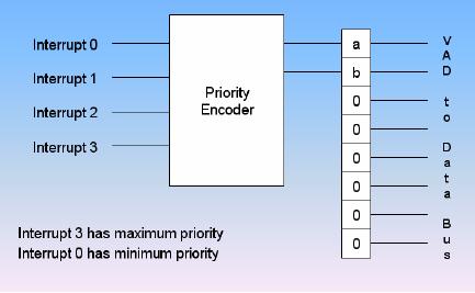
Advanced Computer
Architecture-CS501
________________________________________________________
·
Parallel
priority method for
resolving the priority uses
individual bits of a
priority
encoder.
·
The
priority of the device is
determined by position of the
input of the encoder
used
for the interrupt.
Parallel
Priority Interrupt:
.
Page
281
Last
Modified: 01-Nov-06
Table of Contents:
- Computer Architecture, Organization and Design
- Foundations of Computer Architecture, RISC and CISC
- Measures of Performance SRC Features and Instruction Formats
- ISA, Instruction Formats, Coding and Hand Assembly
- Reverse Assembly, SRC in the form of RTL
- RTL to Describe the SRC, Register Transfer using Digital Logic Circuits
- Thinking Process for ISA Design
- Introduction to the ISA of the FALCON-A and Examples
- Behavioral Register Transfer Language for FALCON-A, The EAGLE
- The FALCON-E, Instruction Set Architecture Comparison
- CISC microprocessor:The Motorola MC68000, RISC Architecture:The SPARC
- Design Process, Uni-Bus implementation for the SRC, Structural RTL for the SRC instructions
- Structural RTL Description of the SRC and FALCON-A
- External FALCON-A CPU Interface
- Logic Design for the Uni-bus SRC, Control Signals Generation in SRC
- Control Unit, 2-Bus Implementation of the SRC Data Path
- 3-bus implementation for the SRC, Machine Exceptions, Reset
- SRC Exception Processing Mechanism, Pipelining, Pipeline Design
- Adapting SRC instructions for Pipelined, Control Signals
- SRC, RTL, Data Dependence Distance, Forwarding, Compiler Solution to Hazards
- Data Forwarding Hardware, Superscalar, VLIW Architecture
- Microprogramming, General Microcoded Controller, Horizontal and Vertical Schemes
- I/O Subsystems, Components, Memory Mapped vs Isolated, Serial and Parallel Transfers
- Designing Parallel Input Output Ports, SAD, NUXI, Address Decoder , Delay Interval
- Designing a Parallel Input Port, Memory Mapped Input Output Ports, wrap around, Data Bus Multiplexing
- Programmed Input Output for FALCON-A and SRC
- Programmed Input Output Driver for SRC, Input Output
- Comparison of Interrupt driven Input Output and Polling
- Preparing source files for FALSIM, FALCON-A assembly language techniques
- Nested Interrupts, Interrupt Mask, DMA
- Direct Memory Access - DMA
- Semiconductor Memory vs Hard Disk, Mechanical Delays and Flash Memory
- Hard Drive Technologies
- Arithmetic Logic Shift Unit - ALSU, Radix Conversion, Fixed Point Numbers
- Overflow, Implementations of the adder, Unsigned and Signed Multiplication
- NxN Crossbar Design for Barrel Rotator, IEEE Floating-Point, Addition, Subtraction, Multiplication, Division
- CPU to Memory Interface, Static RAM, One two Dimensional Memory Cells, Matrix and Tree Decoders
- Memory Modules, Read Only Memory, ROM, Cache
- Cache Organization and Functions, Cache Controller Logic, Cache Strategies
- Virtual Memory Organization
- DRAM, Pipelining, Pre-charging and Parallelism, Hit Rate and Miss Rate, Access Time, Cache
- Performance of I/O Subsystems, Server Utilization, Asynchronous I/O and operating system
- Difference between distributed computing and computer networks
- Physical Media, Shared Medium, Switched Medium, Network Topologies, Seven-layer OSI Model