 |
Preparing source files for FALSIM, FALCON-A assembly language techniques |
| << Comparison of Interrupt driven Input Output and Polling |
| Nested Interrupts, Interrupt Mask, DMA >> |
Advanced Computer
Architecture-CS501
________________________________________________________
Advanced
Computer Architecture
Lecture
No. 29
Reading
Material
Handouts
Slides
Summary
�
Introduction
to FALSIM
�
Preparing
source files for
FALSIM
�
Using
FALSIM
�
FALCON-A
assembly language
techniques
Introduction
to FALSIM:
FALSIM is
the name of the software
application which consists of the
FALCON-A
assembler
and the FALCON-A simulator. It
runs under Windows
XP.
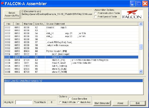
FALCON-A
Assembler:
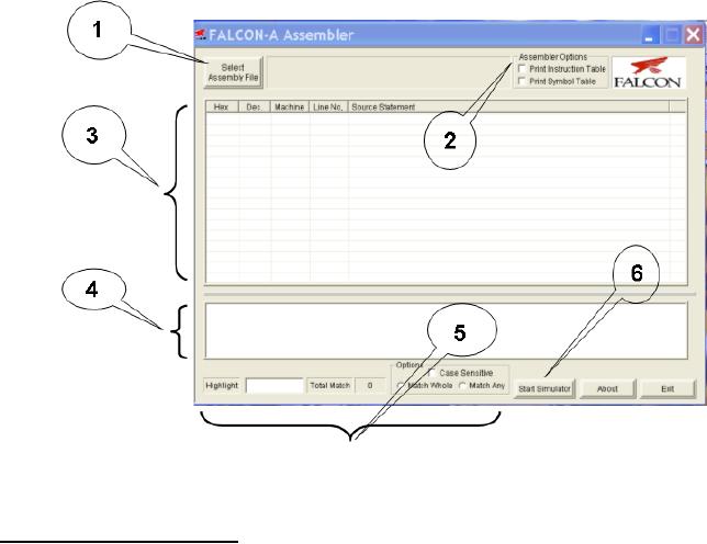
Figure 1
shows a snapshot of the graphical user
interface (GUI) for the
FALCON-A
Assembler.
This tool loads a FALCON-A
assembly file with a
(.asmfa) extension and
parses
it. It shows the parsed
results in an error log,
lets the user view the
assembled file's
contents
in the file listing and also
provides the features of
printing the machine code,
an
Instruction
Table and a Symbol Table to a
FALCON-A listing file. It also
allows the user
to run
the FALCON-A
Simulator.
The
FALCON-A Assembler source code
has two main modules,
the 1st-pass module
and
the
2nd-pass module. The
1st-pass module takes an
assembly file with a
(.asmfa)
extension
and processes the file
contents. It then generates a
Symbol Table which
corresponds to
the storage of all program
variables, labels and data
values in a data
structure
at the implementation level.
The Symbol Table is used by
the 2nd-pass module.
Failures
of the 1st-pass are handled
by the assembler using its
exception handling
mechanism.
The
2nd-pass module sequentially
processes the .asmfa file to
interpret the instruction
op-
codes,
register op-codes and constants
using the Symbol Table. It
then produces a list
file
with a
.lstfa extension independent of
successful or failed pass. If
the pass is successful
a
binary
file with a .binfa extension
is produced which contains
the machine code for
the
program
contained in the assembly
file.
FALCON-A
Simulator:
Figure 6
shows a snapshot of the GUI for
the FALCON-A Simulator. This
tool loads a
FALCON-A
binary file with a (.binfa)
extension and presents its
contents into
different
areas of
the simulator. It allows the
user to execute the program to a
specific point within
a time
frame or just executes it,
line by line. It also allows
the user to view the
registers,
I/O port
values and memory contents as
the instructions
execute.
Page
294
Last
Modified: 01-Nov-06
Advanced Computer
Architecture-CS501
________________________________________________________
FALSIM
Features:
The
FALCON-A Assembler provides
its user with the following
features:
Select
Assembly File: Labeled
as "1" in
Figure 1, this feature
enables the user to
choose
a
FALCON-A assembly file and open it
for processing by the assembler.
Assembler
Options: Labeled
as "2" in
Figure 1.
� Print
Symbol Table
This
feature, if selected, writes the
Symbol Table (produced after
the execution of the
1st-
pass of
the assembler) to a FALCON-A list
file with an extension of
(.lstfa). The Symbol
Table
includes variables, addresses and
labels with their respective
values.
� Print
Instruction Table
This
feature, if selected, writes the
FALCON-A instructions along
with their op-codes
at
the end
of the list file.
List
File: Labeled
as "3", in
Figure 1, the List File
feature gives a detailed
insight of the
FALCON-A
listing file, which is
produced as a result of the
execution of the 1st and
2nd-
pass. It
shows the Program Counter
value in hexadecimal and decimal
formats along with
the
machine code generated for
every line of assembly code.
These values are
printed
when
the 2nd-pass is
completed.
Error
Log: The
Error Log is labeled as "4" in
Figure 1. It informs the user
about the
errors
and their respective details,
which occurs in any of the
two passes of
the
assembler.
The size of this window can be changed by
dragging the boundary line
up or
down.
Highlight:
This
feature is labeled as "5" in
Figure 1 and helps the user to
search for a
certain
input with the options of
searching with "match
whole" and "match
any"
parts
of the
string. The search also has
the option of checking
with/without considering "case-
sensitivity". It
searches the List File
area and highlights the
search results using
the
yellow
color. It also indicates the
total number of matches
found.
Start
Simulator: This
feature is labeled as "6" in
Figure 1. The FALCON-A
Simulator is
run
using the FALCON-A
Assembler's "Start Simulator"
option. Its features are
detailed
as
follows:
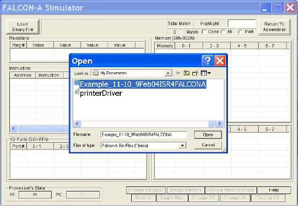
Load
Binary File: The
button labeled as "11" in
Figure 6, allows the user to
choose and
open a
FALCON-A binary file with a
(.binfa) extension. When a
file is being loaded
into
the
simulator all the register,
constants (if any) and
memory values are
set.
Registers:
The
area labeled as "12" in
Figure 6. enables, the user to see
values present in
different
registers before, during and after
execution.
Instruction:
This
area is labeled as "13" in
Figure 6 and contains the
value of PC, address
of an
instruction, its representation in
Assembly, the Register
Transfer Language, the
op-
code and
the instruction type.
I/O
Ports: I/O ports
are labeled as "14" in
Figure 6. These ports are
available for the
user
to enter
input operation values and
visualize output operation
values whenever an I/O
operation
takes place in the program.
The input value for an
input operation is given
by
the user
before an instruction executes. The
output values are visible in
the I/O port area
once the
instruction has successfully
executed.
Memory:
The
memory is divided into two
areas and is labeled as "15" in
Figure 6, to
facilitate
the view of data stored at
different memory locations
before, during and
after
program
execution.
Processor's
State: Labeled
as "16" in
Figure 6, this area shows
the current values of
the
Page
295
Last
Modified: 01-Nov-06
Advanced Computer
Architecture-CS501
________________________________________________________
Instruction
Register and the Program
Counter while the program
executes.
Highlight:
The
highlight option for the
FALCON-A simulator is labeled as
"17"
in
Figure 6.
This feature is similar to
the way the highlight
feature of the
FALCON-A
Assembler
works. It offers to highlight
the search string which is
entered as an input,
with
the "All " and " Part " option. The
results of the search are
highlighted using the
yellow
color. It also indicates the
total number of matches.
The
following is a description of the
options available on the
button panel labeled as "18"
in Figure
6.
Single
Step: "Single
Step" lets the user execute
the program, one instruction at a
time.
The
next instruction is not
executed unless the user
does a "single step" again.
By default,
the
instruction to be executed will be the
one next in the sequence. It
changes if the user
specifies a
different PC value using the
Change PC option (explained
below).
Change
PC: This
option lets the user change
the value of PC (Program
Counter).
By
changing the PC the user can
execute the instruction to
which the specified
PC
points.
The value in the PC must be
an even address.
Execute:
By
choosing this button, the
user is able to execute the loaded
program
with
the options of execution
with/without breakpoint insertion. In
case of
breakpoint
insertion, the user has the
option to choose from a list
of valid
breakpoint
values. It also has the
option to set a limit on the
time for execution.
This
"Max Execution Time" option
restricts the program
execution to a time
frame
specified by the user.
Change
Register: Using
the Change Register feature,
the user can change the
value
present in a particular register.
Change
Memory Word: This
feature enables the user to change
values present at a
particular
memory location.
Display
Memory: Display
Memory shows an updated memory
area, after a
particular
memory location other than
the pre-existing ones is
specified by the
user.
Change
I/O: Allows
the user to give an I/O port
value if the instruction to
be
executed
requires an I/O operation. Giving in
the input in any one of the
I/O ports
areas
before instruction execution,
indicates that a particular I/O
operation will be
a part of
the program and it will have an
input from some source. The
value given
by the
user indicates the input
type and source.
Display
I/O: Display
I/O works in a manner similar to
Display Memory. Here
the
user specifies
the starting index of an I/O
port. This features displays
the I/O ports
stating
from the index
specified.
2.
Preparing Source Files for
FALSIM:
In order
to use the FALCON-A
assembler and simulator, FALSIM,
the source file
containing
assembly language statements and
directives should be
prepared
according
to the following
guidelines:
�
The
source file should contain
ASCII text only. Each line
should be terminated by
a carriage
return. The extension .asmfa
should be
used with each file
name. After
assembly,
a list file with the
original filename and an extension
.lstfa,
and
a
binary
file with an extension .binfa
will
be generated by FALSIM.
Page
296
Last
Modified: 01-Nov-06
Advanced Computer
Architecture-CS501
________________________________________________________
�
Comments
are indicated by a semicolon
(;) and can be placed anywhere in
the
source
file. The FALSIM assembler
ignores any text after
the semicolon.
�
Names in
the source file can be of one of the
following types:
�
Variables:
These are defined using the
.equ
directive.
A value must also be
assigned
to variables when they are
defined.
�
Addresses
in the "data and pointer area"
within the memory: These can be
defined
using
the .dw
or
the .sw
directive.
The difference between these
two directives is
that
when .dw
is
used, it is not possible to store any
value in the memory.
The
integer
after .dw
identifies
the number of memory words
to be reserved starting at
the
current address. (The
directive .db
can
be used to reserve bytes in
memory.)
Using
the .sw
directive,
it is possible to store a constant or the
value of a name in
the
memory. It is also possible to use
pointers with this directive
to specify
addresses
larger than 127. Data tables and
jump tables can also be set up in
the
memory
using this directive.
�
Labels:
An assembly language statement can
have a unique label
associated with
it.
Two assembly language statements
cannot have the same name.
Every label
should
have a colon (:) after
it.
�
Use the
.org
0 directive
as the first line in the
program. Although the use of
this
line is
optional, its use will make sure
that FALSIM will start
simulation by
picking
up the first instruction stored at
address 0 of the memory.
(Address 0 is
called
the reset address of the
processor). A jump
[first] instruction
can be placed
at
address 0, so that control is
transferred to the first
executable statement of
the
main
program. Thus, the label
first
serves as
the identifier of the "entry
point" in
the
source file. The .org
directive
can also be used anywhere in the source
file to
force
code at a particular address in
the memory.
�
Address 2 in
the memory is reserved for
the pointer to the Interrupt
Service
Routine
(ISR). The .sw
directive
can be used to store the address of
the first
instruction
in the ISR at this
location.
Address 4 to 125 can
be used for addresses of
data and pointers20.
However, the
�
main
program must start at
address 126 or less21,
otherwise FALSIM will
generate
an error at the jump
[first] instruction.
�
The
main program should be
followed by any subprograms or procedures.
Each
procedure
should be terminated with a
ret
instruction.
The ISR, if any, should
be
placed
after the procedures and should be
terminated with the iret
instruction.
�
The
last line in the source file
should be the .end
directive.
�
The
.equ
directive
can be used anywhere in the source
file to assign values
to
variables.
�
It is the
responsibility of the programmer to make
sure that code does
not
overwrite
data when the assembly
process is performed, or vice
versa. As an
example,
this can happen if care is not exercised
during the use of the
.org
directive
in the source file.
20
Any
address between 4 and 14 can
be used in place of the
displacement field in load or
store instructions.
Recall
that the displacement field
is just 5 bits in the instruction
word.
21
This
restriction is because of the
fact that the immediate
operand in the movi
instruction
must fit an 8-bit
field in
the instruction word.
Page
297
Last
Modified: 01-Nov-06
Advanced Computer
Architecture-CS501
________________________________________________________
3.
Using FALSIM:
� To
start FALSIM (the FALCON-A
assembler and simulator), double
click on the
FALSIM
icon. This will display the
assembler window, as shown in
the Figure 1.
� Select one or
both assembler options shown
on the top right corner of
the
assembler
window labeled as "2". If no
option is selected, the symbol
table and
the
instruction table will not be
generated in the list
(.lstfa) file.
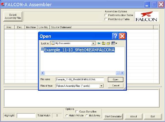
� Click
on the select assembly file
button labeled as "1". This
will open the dialog
box as
shown in the Figure
2.
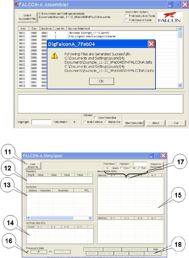
� Select
the path and file containing
the source program that is to be
assembled.
� Click
on the open button. FALSIM will
assemble the program and
generate two
files
with the same filename,
but with different
extensions. A list file will
be
generated
with an extension .lstfa, and a
binary (executable) file will be
generated
with an
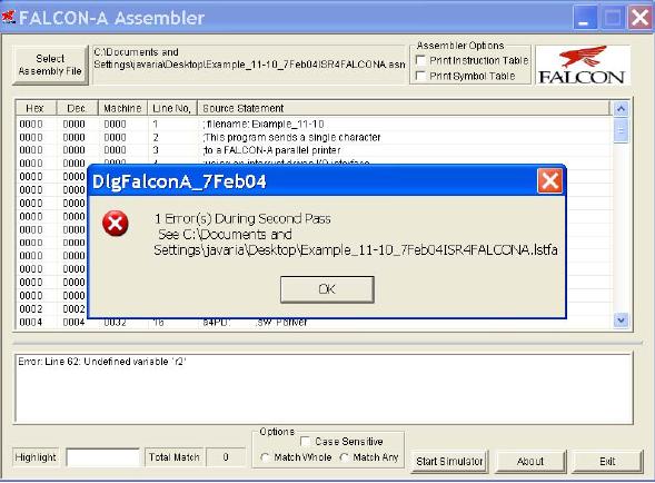
extension .binfa. FALSIM will also
display the list file and
any error
messages
in two separate panes, as
shown in Figure 3.
� Double
clicking on any error
message highlights and displays
the corresponding
erroneous
line in the program listing
window pane for the
user. This is shown
in
Figure 4.
The highlight feature can also be
used to display any text
string,
including
statements with errors in them. If
the assembler reported any
errors in
the
source file, then these
errors should be corrected and
the program should be
assembled
again before simulation can be done.
Additionally, if the source
file
had been
assembled correctly at an earlier
occasion, and a correct binary
(.binfa)
file
exists, the simulator can be started
directly without performing
the assembly
process.
� To
start the simulator, click
on the start simulation
button labeled as "6". This
will
open the
dialog box shown in Figure
6.
� Select
the binary file to be
simulated, and click Open
as
shown in Figure 7. (It is
also possible to open
the file by double clicking
on the file name in the
"Open"
window).
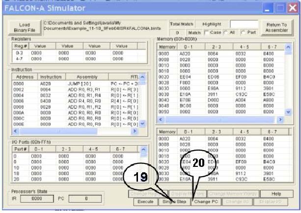
� This
will open the simulation window
with the executable program
loaded in it as
shown in
Figure 8. The details of the
different panes in this
window were given in
section 1
earlier. Notice that the
first instruction at address 0 is
ready for
execution.
All registers are initialized to 0. The
memory contains the address
of
the
ISR (i.e., 64h which is 100
decimal) at location 2 and the
address of the
printer
driver at location 4. These two
addresses are determined at
assembly time
in our
case. In a real situation,
these addresses will be determined at
execution
time by
the operating system, and
thus the ISR and the
printer driver will be
located
in the memory by the
operating system (called
re-locatable code).
Subsequent
memory locations contain
constants defined in the
program.
� Click
single step button labeled
as "19". FALSIM
will execute the jump
[main]
instruction
at address 0 and the PC will change to
20h (32 decimal), which is
the
address
of the first instruction in
the main program (i.e.,
the value of main).
� Although
in a real situation, there will be
many instructions in the
main program,
those
instructions are not present in
the dummy calling program.
The first useful
instruction
is shown next. It loads the
address of the printer
driver in r6 from the
pointer
area in the memory. The
registers r5 and r7 are also set up for
passing the
Page
298
Last
Modified: 01-Nov-06
Advanced Computer
Architecture-CS501
________________________________________________________
starting
address of the print buffer
and the number of bytes to be
printed. In our
dummy
program, we bring these
values in to these registers from
the data area in
the
memory, and then pass these
values to the printer driver
using these two
registers.
Clicking on the single step
button twice, executes these
two instructions.
�
The
execution of the call
instruction simulates the
event of a print request by
the
user.
This transfers control to
the printer driver. Thus,
when the call
r4, r6
instruction
is single stepped, the PC
changes to 32h (50 decimal)
for executing the
first
instruction in the printer
driver.
�
Double
click on memory location
000A, which is being used
for holding the PB
(printer
busy) flag. Enter a 1 and
click the change memory
button. This will store
a 0001 in
this location, indicating
that a previous print job is
in progress. Now
click
single step and note that
this value is brought from
memory location 000E
into
register r1. Clicking single
step again will cause the jnz
r1, [message]
instruction
to execute, and control will transfer to
the message routine at
address
0046h.
The nop
instruction
is used here as a place holder.
�
Click
again on the single step
button. Note that when
the ret
r4 instruction
executes,
the value in r4 (i.e., 28h)
is brought into the PC.
The blue highlight
bar
is placed on
the next instruction after
the call
r4, r6 instruction
in the main
program.
In case of the dummy calling
program, this is the halt
instruction.
�
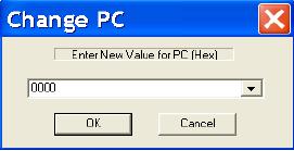
Double
click on the value of the PC
labeled as "20". This
will open a dialog box
shown
below. Enter a value of the
PC (i.e.,
26h)
corresponding to the call
r4, r6
instruction,
so that it can be executed
again. A
"list" of possible PC values can
also be
pulled down using, and 0026h
can
be
selected from there as
well.
�
Click
single step again to enter
the printer
driver
again.
�
Change
memory location 000A to a 0, and
then single step the
first instruction in
the
printer driver. This will
bring a 0 in r1, so that
when the next jnz
r1,
[message]
instruction
is executed, the branch will
not be taken and control
will
transfer
to the next instruction
after this instruction. This
is movi
r1, 1 at
address
0036h.
�
Continue
single stepping.
�
Notice
that a 1 has been stored in
memory location 000A, and r1
contains 11h,
which is
then transferred to the
output port at address 3Ch
(60 decimal) when
the
out
r1, controlp instruction
executes. This can be verified by double
clicking on
the
top left corner of the I/O
port pane, and changing the
address to 3Ch.
Another
way to
display the value of an I/O
port is to scroll the I/O
window pane to the
desired
position.
�
Continue
single stepping till the
int
instruction
and note the changes in
different
panes of
the simulation window at
each step.
�
When
the int
instruction
executes, the PC changes to 64h,
which is the address
of
the
first instruction in the
ISR. Clicking single step
executes this instruction, and
loads the
address of temp
(i.e.,
0010h) which is a temporary
memory area for
Page
299
Last
Modified: 01-Nov-06
Advanced Computer
Architecture-CS501
________________________________________________________
storing
the environment. The five
store
instructions
in the ISR save the
CPU
environment
(working registers) before
the ISR change them.
�
Single
step through the ISR
while noting the effects on
various registers, memory
locations,
and I/O ports till the iret
instruction
executes. This will pass
control
back to
the printer driver by
changing the PC to the
address of the jump
[finish]
instruction,
which is the next
instruction after the int
instruction.
�
Double
click on the value of the
PC. Change it to point to the
int
instruction
and
click
single step to execute it
again. Continue to single
step till the in
r1, statusp
instruction
is ready for
execution.
�
Change
the I/O port at address 3Ah
(which represents the status
port at address
58) to 80
and then single step the
in
r1, statusp instruction.
The value in r1
should be
0080.
Single
step twice and notice that
control is transferred to the
movi
r7, FFFF22
�
instruction,which
stores an error code of 1 in
r1.
Figure
1
22
The
instruction was originally movi
r7, -1. Since it
was converted to machine
language by the
assembler,
and
then reverse assembled by
the simulator, it became movi
r7, FFFF. This is
because the machine
code
stores
the number in 16-bits after
sign-extension. The result
will be the same in both
cases.
Page
300
Last
Modified: 01-Nov-06
Advanced Computer
Architecture-CS501
________________________________________________________
Page
301
Last
Modified: 01-Nov-06
Advanced Computer
Architecture-CS501
________________________________________________________
Figure
2
Page
302
Last
Modified: 01-Nov-06
Advanced Computer
Architecture-CS501
________________________________________________________
Figure
3
Page
303
Last
Modified: 01-Nov-06
Advanced Computer
Architecture-CS501
________________________________________________________
Figure
4
Figure
5
Figure
6
Page
304
Last
Modified: 01-Nov-06
Advanced Computer
Architecture-CS501
________________________________________________________
Figure
7
Page
305
Last
Modified: 01-Nov-06
Advanced Computer
Architecture-CS501
________________________________________________________
Figure
8
Page
306
Last
Modified: 01-Nov-06
Advanced Computer
Architecture-CS501
________________________________________________________
4.
FALCON-A assembly language
programming techniques:
� If a signed
value, x, cannot fit in 5
bits (i.e., it is outside
the range -16 to
+15),
FALSIM
will report an error with a
load
r1, [x] or a store
r1, [x] instruction.
To
overcome
this problem, use movi
r2, x followed
by load
r1, [r2].
� If a signed
value, x, cannot fit in 8
bits (i.e., it is outside
the range
-128 to
+127),
even
the previous scheme will not
work. FALSIM will report an
error with the movi
r2,
x instruction.
The following instruction
sequence should be used to
overcome this
limitation
of the FALCON-A. First store
the 16-bit address in the
memory using the
.sw
directive.
Then use two load
instructions as shown
below:
a:
.sw
x
load
r2, [a]
load
r1, [r2]
This is
essentially a "memory-register-indirect" addressing.
It has been made
possible
by the
.sw
directive.
The value of a
should be
less than 15.
� A
similar technique can be used
with immediate ALU instructions
for large values of
the
immediate data, and with the
transfer of control (call and
jump) instructions
for
large
values of the target
address.
� Large
values (16-bit values) can also be stored
in registers using the mul
instruction
combined
with the addi
instruction.
The following instructions
bring a 201 in register
r1.
Page
307
Last
Modified: 01-Nov-06
Advanced Computer
Architecture-CS501
________________________________________________________
movi
r2, 10
movi
r3, 20
mul
r1, r2, r3
; r1
contains 200 after this
instruction
addi
r1, r1, 1
; r1
now contains 201
�
Moving
from one register to another can be done
by using the instruction addi
r2,
r1,
0.
�
Bit
setting and clearing can be done using
the logical (and, or,
not, etc)
instructions.
�
Using
shift instructions (shiftl,
asr, etc.) is faster that
mul
and
div,
if
the multiplier or
divisor
is a power of 2.
Page
308
Last
Modified: 01-Nov-06
Table of Contents:
- Computer Architecture, Organization and Design
- Foundations of Computer Architecture, RISC and CISC
- Measures of Performance SRC Features and Instruction Formats
- ISA, Instruction Formats, Coding and Hand Assembly
- Reverse Assembly, SRC in the form of RTL
- RTL to Describe the SRC, Register Transfer using Digital Logic Circuits
- Thinking Process for ISA Design
- Introduction to the ISA of the FALCON-A and Examples
- Behavioral Register Transfer Language for FALCON-A, The EAGLE
- The FALCON-E, Instruction Set Architecture Comparison
- CISC microprocessor:The Motorola MC68000, RISC Architecture:The SPARC
- Design Process, Uni-Bus implementation for the SRC, Structural RTL for the SRC instructions
- Structural RTL Description of the SRC and FALCON-A
- External FALCON-A CPU Interface
- Logic Design for the Uni-bus SRC, Control Signals Generation in SRC
- Control Unit, 2-Bus Implementation of the SRC Data Path
- 3-bus implementation for the SRC, Machine Exceptions, Reset
- SRC Exception Processing Mechanism, Pipelining, Pipeline Design
- Adapting SRC instructions for Pipelined, Control Signals
- SRC, RTL, Data Dependence Distance, Forwarding, Compiler Solution to Hazards
- Data Forwarding Hardware, Superscalar, VLIW Architecture
- Microprogramming, General Microcoded Controller, Horizontal and Vertical Schemes
- I/O Subsystems, Components, Memory Mapped vs Isolated, Serial and Parallel Transfers
- Designing Parallel Input Output Ports, SAD, NUXI, Address Decoder , Delay Interval
- Designing a Parallel Input Port, Memory Mapped Input Output Ports, wrap around, Data Bus Multiplexing
- Programmed Input Output for FALCON-A and SRC
- Programmed Input Output Driver for SRC, Input Output
- Comparison of Interrupt driven Input Output and Polling
- Preparing source files for FALSIM, FALCON-A assembly language techniques
- Nested Interrupts, Interrupt Mask, DMA
- Direct Memory Access - DMA
- Semiconductor Memory vs Hard Disk, Mechanical Delays and Flash Memory
- Hard Drive Technologies
- Arithmetic Logic Shift Unit - ALSU, Radix Conversion, Fixed Point Numbers
- Overflow, Implementations of the adder, Unsigned and Signed Multiplication
- NxN Crossbar Design for Barrel Rotator, IEEE Floating-Point, Addition, Subtraction, Multiplication, Division
- CPU to Memory Interface, Static RAM, One two Dimensional Memory Cells, Matrix and Tree Decoders
- Memory Modules, Read Only Memory, ROM, Cache
- Cache Organization and Functions, Cache Controller Logic, Cache Strategies
- Virtual Memory Organization
- DRAM, Pipelining, Pre-charging and Parallelism, Hit Rate and Miss Rate, Access Time, Cache
- Performance of I/O Subsystems, Server Utilization, Asynchronous I/O and operating system
- Difference between distributed computing and computer networks
- Physical Media, Shared Medium, Switched Medium, Network Topologies, Seven-layer OSI Model