 |
VU
Information
System (CS507)
LESSON
19
System
Design
System
design can be explained and
presented in narrative form. But the
benefits of diagrammatic view
cannot be
understated. This helps to give a
snapshot of what the entire system looks
like. Various
diagrammatic
tools can be used while
designing the system.
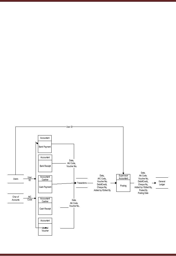
As an
example consider the following
DFD which indicates a simple
process of recording transactions
and
posting
into general ledger
78
VU
Information
System (CS507)
User/Accountant
uses chart of accounts to
access the relevant accounts in order to
prepare different
vouchers
according to requirements. The
purpose behind this entire activity is to
record various
transactions.
The next step is posting of
all these transactions in the
system. This process updates
the
general
ledger.
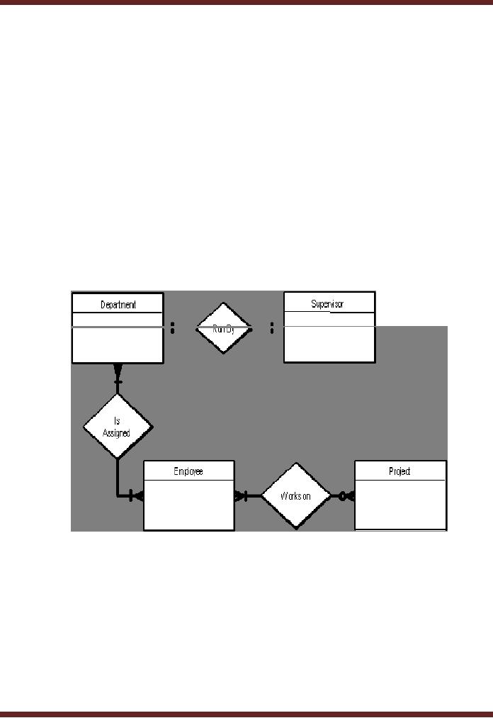
19.1
Entity Relationship Diagram
(ERD)
Another
diagrammatical tool used in
system design is ERD. ERD as
shown below indicates
simple
relationships.
These relationships can be read as
follows.
· One
department has one
supervisor
· A department
may have more than one
employees
Or
· An
employee may be in more than
one departments
· An
employee may not be working
on any project but a project
must have at least one
employee working
on
it
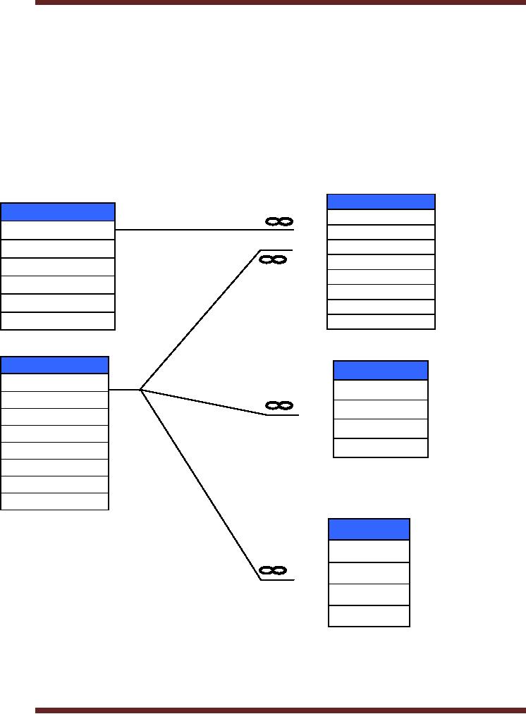
This is another
form of ERD used to show the
relations between various fields in files
used to record
specific
data.
79
VU
Information
System (CS507)
Reservation
1
Reservation
ID
Room
ID
Room
ID
User
ID
Manager
Date
Building
Start
time
Room
End
time
Description
Note
Status
Status
1
User
Session
User
ID
Session
ID
First
User
ID
Last
Session
String
Login
Time
Stamp
Password
Type
Initials
Status
Log
Log
ID
User
ID
Time
Stamp
In/out
The
above figure shows a hotel
booking system. Various records
have been kept for
each entity.
However
each entity shares a relationship
with for logical purpose.
For instance, the field for
room ID
has
been kept in reservation for
access to further data. User
information has been kept
separate,
however
link has been made to
reservation, session and
logs by making user ID common to all
three
tables.
Such kind of relationship helps in
keeping
80

VU
Information
System (CS507)
19.2
Design of the information
flow
It is a major
step in the conceptual design.
Following aspects should be
covered
·
Flow
of data & information and
transformation points
·
The
frequency and timing of
flows
·
The
extent of formality in these flows
input forms, report
formats.
19.3
Design of data base
It
involves determining scope and
structure:
·
Scope
Whether the database is local or global. If
interdependence of organizational units is
high,
the data base has to be global in
order to prevent sub-optimization of
sub units. As it
becomes
global, the cost of maintenance
enhances.
·
Structure
refers to the ways data is
stored in partitions and
sequences. Various
design
methodologies
can be used for devising a
suitable structure in accordance
with the needs of the
organization
and the new system.
19.4
Design of the User Interface
This
phase involves determining the ways the
information system will interact
with the users. Some
elements
are
·
Source
Documents to capture raw
data
·
Hard-copy
output reports
·
Screen
layouts
·
Inquiry
screens
·
Interrogation
languages for the data
base
·
Graphics
and colour displays
·
Voice
output to guide users or
answer queries
·
Screen
layouts for manipulation by a
light pen or mouse
·
Icons
for pictorial
representations
The
design process begins with
stratifying system users and
then identifying their
needs. e.g.
·
New
users dealing with system
infrequently,
·
Experts
dealing regularly
19.5
Physical Design
The
logical design is converted to physical
design in this phase. The
physical design involves breaking
up the logical
design into units, which in
turn can be decomposed
further into implementation
units
such
as programs and
modules.
Design of
the Hardware/ Software
Platform
New
system requires new software
and hardware not currently
available in the organization.
For
example
81

VU
Information
System (CS507)
·
User
workstations might have to be purchased
to support an office automation
system.
·
A
minicomputer might have to be
purchased to provide extra
processing resources to the
new
system.
19.6
Program Development
The
development phase involves converting
design specifications into
executable programs. Once
the
analysis
and design is complete, the
software is either developed according to the
needs or most suitable
is
purchased.
Similarly the specifications of the hardware
are seen and acquisition is
made according to the
situation.
Primary procedural programming activities
include
·
The
creation and testing of source
code
·
The
refinement and finalization of test
plans
·
Writing
and reviewing program modules or
components
·
Integration
of Completed components with other
components to ensure the components
properly
interact.
The process continues as component
groups are progressively integrated
and as interfaces
between
component
groups
and
other
systems
are
tested.
19.7
Procedures Development
In this
phase, following documents
are prepared.
·
Technical
manual This is meant for the Data
Base Management and
highlights the system
infrastructure,
inputs-outputs of the system and flows of
system processes. Documents
include
·
DFD's
(Data Flow Diagrams)
·
ERD's
(Entity Relationship Diagram)
·
Use
cases, test cases
·
User
manual
It
defines the operations of the system in
layman's terms i.e.
·
Getting
started with the
software
·
Operating the
software
·
These
manuals are generally
function related.
19.8
Testing
The
purpose of this phase is to identify as
far as possible any errors
and deficiencies in the system
prior to
its
final release into
production use. For instance
errors in
·
User
interface
·
Procedure
manuals
·
Job
design
·
Organizational
structure design
In reality
all system features cannot be
checked at the outset. For
instance, users might
realize that the
system
has inadequate procedures
manual only after the system
has been properly
implemented.
Change
Over
This
phase comprises of those activities
undertaken to replace the new system in
operation from the
82

VU
Information
System (CS507)
existing
system. Following ways of
change over can be
undertaken
·
Abrupt
change over stop the existing
system abruptly to shift
over to new one
·
Phased
change over Both are
run but output of both the
systems is used since
functions
performed
are different.
·
Parallel
change over Both
systems are run
simultaneously for a period of time
and output of
either of the
systems is used. Functions performed by
both are same.
19.9
Operations & Maintenance
The
new system is run as a
production system and is periodically
modified to adjust for better
functioning.
Following
can be various forms of
errors.
·
Removal
of coding/logic errors Logic
errors discovered in the system
are corrected.
·
Modifications
/ system rewrite Changes in the
system environment may
necessitate system
modifications.
·
Perfective
maintenance Changes might be
made to improve processing
efficiency.
19.10
Evaluating Waterfall
Arguments
for water fall
·
Waterfall model
places emphasis on documentation (such as
requirements documents and
design
documents)
as well as source
code.
·
Other
methodologies which save time in software
development can de-emphasize documentation.
In
such
methodologies project knowledge is stored mentally by
team members. Should team
members
leave,
this knowledge is lost, and substantial
loss of project knowledge may be
difficult for a project
to
recover
from. Extreme Programming is an example
which will be discussed
later.
·
Waterfall model is
preferred for its simple and
arguably more disciplined approach.
The model itself
progresses
linearly through discrete,
easily understandable and explainable
"phases" and is thus easy
to
understand
·
It
also provides easily mark
able "milestones" in the development process. It is
perhaps for this
reason
that
the waterfall model is used as a beginning
example of a development model in many
software
engineering
texts and courses.
Arguments
against water fall
·
It is
argued that it is impossible to
get one phase of a software
product's lifecycle "perfected"
before
moving
on to the next phases and learning
from them.
For
example clients may not be
aware of exactly what requirements they
want before they see a working
prototype
and can comment upon it -
they may change their
requirements constantly, and
program
designers.
This is an example of iterative model
(to be discussed
later)
·
Waterfall model
advocates more reliance on
fixed, static requirements.
Designers may not be
fully
aware
of future implementation difficulties
when writing a design for an
unimplemented software
product.
That is, it may become
clear in the implementation phase
that a particular area of program
functionality
is extraordinarily difficult to
implement.
·
Another
problem is that the waterfall model
assumes that the only role
for users is in
specifying
requirements,
and that all requirements
can be specified in advance.
Unfortunately, requirements grow
83
VU
Information
System (CS507)
and
change throughout the process
and beyond, calling for considerable
feedback and
iterative
consultation.
Thus many other SDLC
models have been developed.
The choice of phases differs
in
various
standards and
organizations.
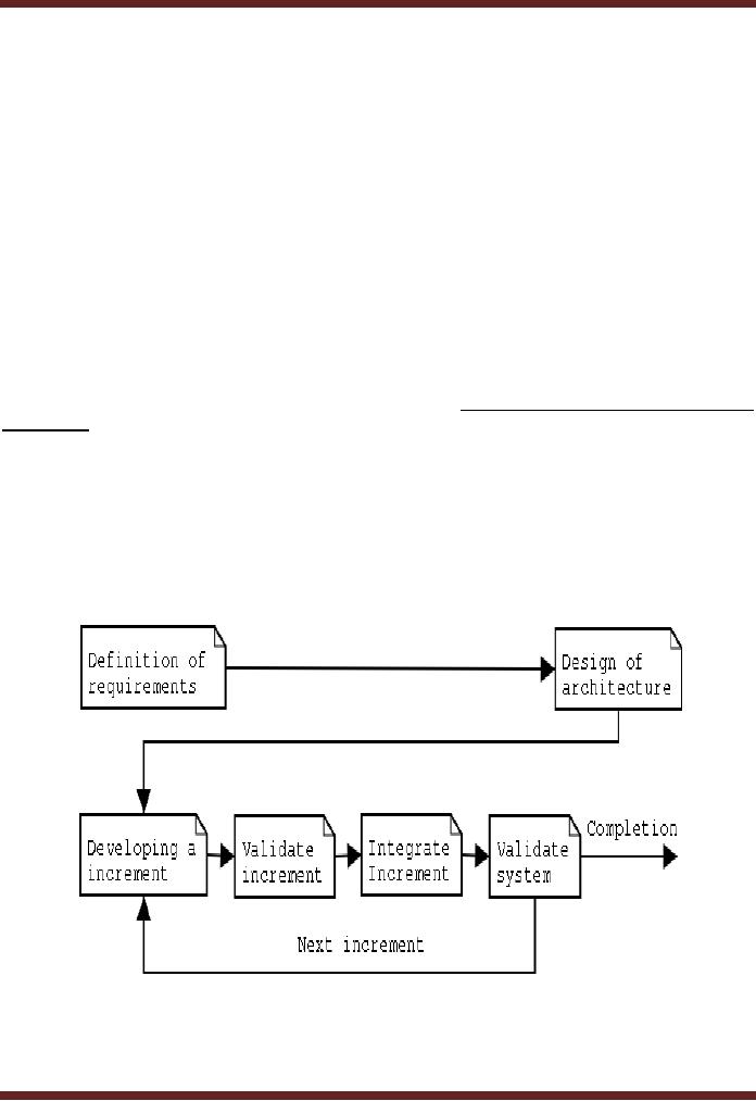
LESSON
20
Incremental
Model
The
incremental model is a method of software/
Information System development where the
model is
designed,
implemented and tested incrementally
until the product is finished. It
involves both development
and
maintenance. This model combines the
elements of the waterfall model with the
philosophy of
prototyping.
Example
-An
example of this incremental approach is
observed in the development of word
processing
applications
where the following services
are provided on subsequent
modules:
·
Basic
file management, editing and
document production functions
·
Advanced
editing and document production
functions
·
Spell
and grammar checking
·
Advance
page layout
84
Table of Contents:
- Need for information, Sources of Information: Primary, Secondary, Tertiary Sources
- Data vs. Information, Information Quality Checklist
- Size of the Organization and Information Requirements
- Hierarchical organization, Organizational Structure, Culture of the Organization
- Elements of Environment: Legal, Economic, Social, Technological, Corporate social responsibility, Ethics
- Manual Vs Computerised Information Systems, Emerging Digital Firms
- Open-Loop System, Closed Loop System, Open Systems, Closed Systems, Level of Planning
- Components of a system, Types of Systems, Attributes of an IS/CBIS
- Infrastructure: Transaction Processing System, Management Information System
- Support Systems: Office Automation Systems, Decision Support Systems, Types of DSS
- Data Mart: Online Analytical Processing (OLAP), Types of Models Used in DSS
- Organizational Information Systems, Marketing Information Systems, Key CRM Tasks
- Manufacturing Information System, Inventory Sub System, Production Sub System, Quality Sub system
- Accounting & Financial Information Systems, Human Resource Information Systems
- Decision Making: Types of Problems, Type of Decisions
- Phases of decision-making: Intelligence Phase, Design Phase, Choice Phase, Implementation Phase
- Planning for System Development: Models Used for and Types of System Development Life-Cycle
- Project lifecycle vs. SDLC, Costs of Proposed System, Classic lifecycle Model
- Entity Relationship Diagram (ERD), Design of the information flow, data base, User Interface
- Incremental Model: Evaluation, Incremental vs. Iterative
- Spiral Model: Determine Objectives, Alternatives and Constraints, Prototyping
- System Analysis: Systems Analyst, System Design, Designing user interface
- System Analysis & Design Methods, Structured Analysis and Design, Flow Chart
- Symbols used for flow charts: Good Practices, Data Flow Diagram
- Rules for DFDs: Entity Relationship Diagram
- Symbols: Object-Orientation, Object Oriented Analysis
- Object Oriented Analysis and Design: Object, Classes, Inheritance, Encapsulation, Polymorphism
- Critical Success Factors (CSF): CSF vs. Key Performance Indicator, Centralized vs. Distributed Processing
- Security of Information System: Security Issues, Objective, Scope, Policy, Program
- Threat Identification: Types of Threats, Control Analysis, Impact analysis, Occurrence of threat
- Control Adjustment: cost effective Security, Roles & Responsibility, Report Preparation
- Physical vs. Logical access, Viruses, Sources of Transmissions, Technical controls
- Antivirus software: Scanners, Active monitors, Behavior blockers, Logical intrusion, Best Password practices, Firewall
- Types of Controls: Access Controls, Cryptography, Biometrics
- Audit trails and logs: Audit trails and types of errors, IS audit, Parameters of IS audit
- Risk Management: Phases, focal Point, System Characterization, Vulnerability Assessment
- Control Analysis: Likelihood Determination, Impact Analysis, Risk Determination, Results Documentation
- Risk Management: Business Continuity Planning, Components, Phases of BCP, Business Impact Analysis (BIA)
- Web Security: Passive attacks, Active Attacks, Methods to avoid internet attacks
- Internet Security Controls, Firewall Security SystemsIntrusion Detection Systems, Components of IDS, Digital Certificates
- Commerce vs. E-Business, Business to Consumer (B2C), Electronic Data Interchange (EDI), E-Government
- Supply Chain Management: Integrating systems, Methods, Using SCM Software
- Using ERP Software, Evolution of ERP, Business Objectives and IT
- ERP & E-commerce, ERP & CRM, ERP Ownership and sponsor ship
- Ethics in IS: Threats to Privacy, Electronic Surveillance, Data Profiling, TRIPS, Workplace Monitoring