 |
6
Display
Memory
The
debugger gives a very close
vision of the processor.
That is why every
program
written till now was executed
inside the debugger. Also
the
debugger
is a very useful tool in
assembly language program
development,
since
many bugs only become
visible when each
instruction is independently
monitored
the way the debugger allows
us to do. We will now be using
the
display
screen in character mode,
the way DOS uses this
screen. The way we
will
access this screen is
specific to the IBM
PC.
6.1.
ASCII CODES
The
computer listens, sees, and
speaks in numbers. Even a
character is a
number
inside the computer. For
example the keyboard is
labeled with
characters
however when we press `A', a
specific number is transferred
from
the
keyboard to the computer. Our
program interprets that
number as the
character
`A'. When the same
number comes on display, the
Video Graphics
Adapter
(VGA) in our computer shows
the shape of `A'. Even
the shape is
stored
in binary numbers with a one bit
representing a pixel on the
screen
that is
turned on and a zero bit
representing a pixel that is
not glowing. This
example
is considering a white on black
display and no colors. This
is the
way a
shape is drawn on the
screen. The interpretation of `A' is
performed by
the
VGA card, while the
monitor or CRT (cathode ray
tube) only glows
the
pixels
on and turns them off. The
keyboard has a key labeled
`A' and
pressing
it the screen shows `A' but
all that happened inside was
in
numbers.
An `A' on
any computer and any
operating system is an `A' on every
other
computer
and operating system. This
is because a standard
numeric
representation
of all commonly used
characters has been
developed. This is
called
the ASCII code, where
ASCII stands for American
Standard Code for
Information
Interchange. The name
depicts that this is a code
that allows the
interchange
of information; `A' written on one
computer will remain an `A' on
another.
The ASCII table lists
all defined characters and
symbols and their
standardized
numbers. All ASCII based
computers use the same
code. There
are
few other standards like
EBCDIC and gray codes, but
ASCII has become
the
most prevalent standard and
is used for Internet
communication as well.
It has
become the de facto standard
for global communication.
The character
mode
displays of our computer use
the ASCII standard. Some
newer
operating
systems use a new standard
Unicode but it is not relevant to us
in
the
current discussion.
Standard
ASCII has 128 characters
with assigned numbers from 0 to
127.
When
IBM PC was introduced, they extended
the standard ASCII and
defined
128
more characters. Thus
extending the total number
of symbols from 128
to 256
numbered from 0 to 255
fitting in an 8-bit byte.
The newer characters
were
used for line drawing,
window corners, and some
non-English
characters.
The need for these
characters was never felt on
teletype
terminals,
but with the advent of IBM PC and
its full screen display,
these
semi-graphics
characters were the need of
the day. Keep in mind that
at that
time
there was no graphics mode
available.
The
extended ASCII code is just
a de facto industry standard but it is
not
defined
by an organization like the
standard ASCII. Printers,
displays, and all
other
peripherals related to the IBM PC
understand the ASCII code.
If the
Computer
Architecture & Assembly Language
Programming
Course
Code: CS401
CS401@vu.edu.pk
code
for `A' is sent to the
printer, the printer will
print the shape of `A', if
it is
sent to
the display, the VGA
card will form the shape of
`A' on the CRT. If it is
sent to
another computer via the
serial port, the other
computer will
understand
that this is an `A'.
The
important thing to observe in
the ASCII table is the
contiguous
arrangement
of the uppercase alphabets
(41-5A), the lowercase
alphabets
(61-7A),
and the numbers (30-39).
This helps in certain
operations with
ASCII,
for example converting the
case of characters by adding or
subtracting
0x20
from it. It also helps in
converting a digit into its
ASCII representation
by
adding 0x30 to it.
6.2.
DISPLAY MEMORY
FORMATION
We will
explore the working of the
display with ASCII codes,
since it is our
immediately
accessible hardware. When 0x40 is
sent to the VGA card, it
will
turn
pixels on and off in such a
way that a visual representation of
`A'
appears
on the screen. It has no
reality, just an interpretation. In
later
chapters
we will program the VGA
controller to display a new shape
when
the
ASCII of `A' is received by
it.
The
video device is seen by the
computer as a memory area
containing the
ASCII
codes that are currently
displayed on the screen and
a set of I/O ports
controlling
things like the resolution,
the cursor height, and
the cursor
position.
The VGA memory is seen by
the computer just like
its own memory.
There
is no difference; rather the
computer doesn't differentiate, as it
is
accessible
on the same bus as the
system memory. Therefore if
that
appropriate
block of the screen is
cleared, the screen will be
cleared. If the
ASCII
of `A' is placed somewhere in
that block, the shape of `A'
will appear on
the
screen at a corresponding
place.
This
correspondence must be defined as the
memory is a single
dimensional
space while the screen is
two dimensional having 80 rows
and
25
columns. The memory is
linearly mapped on this two
dimensional space,
just
like a two dimensional is mapped in
linear memory. There is one
word
per
character in which a byte is needed
for the ASCII code
and the other
byte
is used
for the character's
attributes discussed later. Now
the first 80 words
will
correspond to the first row of
the screen and the
next 80 words will
correspond
to the next row. By making
the memory on the video
controller
accessible
to the processor via the
system bus, the processor is
now in
control
of what is displayed on the
screen.
The
three important things that
we discussed are.
· One
screen location corresponds to a
word in the video
memory
· The
video controller memory is
accessible to the processor
like its
own
memory.
· ASCII
code of a character placed at a
cell in the VGA memory
will
cause
the corresponding ASCII
shape to be displayed on
the
corresponding
screen location.
Display
Memory Base
Address
The
memory at which the video
controller's memory is mapped must be
a
standard,
so that the program can be
written in a video card
independent
manner.
Otherwise if different vendors map
their video memory at
different
places
in the address space, as was
the problem in the start,
writing software
was a
headache. BIOS vendors had a
problem of dealing with various
card
vendors.
The IBM PC text mode color
display is now fixed so that
system
software
can work uniformly. It was fixed at
the physical memory location
of
B8000.
The first byte at this
location contains the ASCII
for the character
displayed
at the top left of the
video screen. Dropping the
zero we can load
the
rest in a segment register to
access the video memory. If
we do something
in this
memory, the effect can be
seen on the screen. For
example we can
72
Computer
Architecture & Assembly Language
Programming
Course
Code: CS401
CS401@vu.edu.pk
write a
virus that makes any
character we write drop to
the bottom of the
screen.
Attribute
Byte
The
second byte in the word
designated for one screen
location holds the
foreground
and background colors for
the character. This is
called its video
attribute.
So the pair of the ASCII
code in one byte and
the attribute in the
second
byte makes the word
that corresponds to one
location on the
screen.
The
lower address contains the
code while the higher
one contains the
attribute.
The attribute byte as
detailed below has the
RGB for the
foreground
and the background. It has
an intensity bit for the
foreground
color
as well thus making 16 possible
colors of the foreground and
8 possible
colors
for the background. When bit
7 is set the character keeps
on blinking
on the
screen. This bit has some
more interpretations like
background
intensity
that has to be activated in
the video controller through
its I/O
ports.
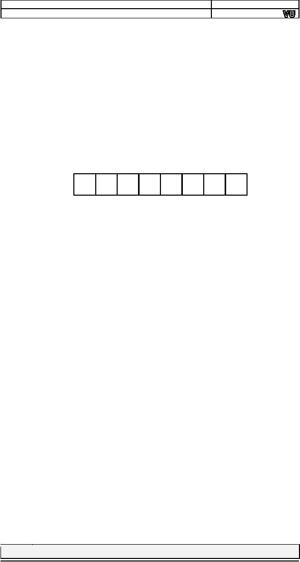
7
6
5
4
3
2
1
0
7
Blinking
of foreground character
6
Red
component of background
color
5
Green
component of background
color
4
Blue
component of background
color
3
Intensity
component of foreground
color
2
Red
component of foreground
color
1
Green
component of foreground
color
0
Blue
component of foreground
color
Display
Examples
Both DS
and ES can be used to access
the video memory. However
we
commonly
keep DS for accessing our
data, and load ES with the
segment of
video
memory. Loading a segment
register with an immediate operand is
not
allowed
in the 8088 architecture. We
therefore load the segment
register via a
general
purpose register. Other
methods are loading from a
memory location
and a
combination of push and
pop.
mov
ax,
0xb800
mov
es, ax
This
operation has opened a window to
the video memory. Now
the
following
instruction will print an `A' on the
top left of the screen in
white
color
on black background.
mov
word [es:0],
0x0741
The
segment override is used
since ES is pointing to the
video memory.
Since
the first word is written
to, the character will
appear at the top left
of
the
screen. The 41 that goes in
the lower byte is the
ASCII code for `A'.
The
07 that
goes in the higher byte is
the attribute with I=0, R=1,
G=1, B=1 for
the
foreground, meaning white
color in low intensity and
R=0, G=0, B=0 for
the
background meaning black
color and the most
significant bit cleared so
that
there is no blinking. Now consider
the following
instruction.
mov
word [es:160],
0x1230
This is
displayed 80 words after the
start and there are 80
characters in
one
screen row. Therefore this
is displayed on the first
column of the second
line.
The ASCII code used is
30, which represents a `0' while
the attribute
byte is
12 meaning green color on
black background.
We take
our first example to clear
the screen.
Example
6.1
73
Computer
Architecture & Assembly Language
Programming
Course
Code: CS401
CS401@vu.edu.pk
01
; clear the
screen
02
[org
0x0100]
03
mov ax,
0xb800
; load video base
in ax
04
mov es,
ax
; point es to video
base
05
mov di,
0
; point di to top left
column
06
07
nextchar:
mov
word [es:di],
0x0720
; clear next char on
screen
08
add
di, 2
;
move to next
screen location
09
cmp
di,
4000
;
has the
whole screen cleared
10
jne
nextchar
;
if no clear next
position
11
12
mov
ax,
0x4c00
; terminate
program
13
int
0x21
The
code for space is 20 while
07 is the normal attribute of
low
07
intensity
white on black with no blinking.
Even to clear the screen
or
put a
blank on a location there is a
numeric code.
08
DI is
incremented twice since each
screen location corresponds
to
two
byte in video memory.
09
DI is
compared with 80*25*2=4000. The
last word location
that
corresponds
to the screen is
3998.
Inside
the debugger the operation
of clearing the screen
cannot be
observed
since the debugger
overwrites whatever is displayed on
the screen.
Directly
executing the COM file from
the command prompt*, we can see
that
the
screen is cleared. The
command prompt that
reappeared is printed
after
the
termination of our application. This is
the first application that
can be
directly
executed to see some output
on the screen.
6.3.
HELLO WORLD IN ASSEMBLY
LANGUAGE
To
declare a character in assembly
language, we store its ASCII
code in a
byte.
The assembler provides us with
another syntax that doesn't
forces us to
remember
the ASCII code. The
assembler also provides a
syntax that
simplifies
declaration of consecutive characters,
usually called a string.
The
three
ways used below are
identical in their
meaning.
db
0x61, 0x61,
0x63
db
'a', 'b',
'c'
db
'abc'
When
characters are stored in any
high level or low level
language the
actual
thing stored in a byte is
their ASCII code. The
only thing the
language
helps
in is a simplified declaration.
Traditionally
the first program in higher
level languages is to print
"hello
world"
on the screen. However due
to the highly granular
nature of assembly
language,
we are only now able to
write it in assembly language. In
writing
this
program, we make a generic
routine that can print
any string on the
screen.
Example
6.2
01
; hello world in
assembly
02
[org
0x0100]
03
jmp
start
04
05
message:
db
'hello
world'
; string to be
printed
06
length:
dw
11
; length of the
string
07
08
; subroutine to clear the
screen
09
clrscr:
push
es
10
push
ax
11
push
di
Remember
that if this example is run in a
DOS window on some
newer
*
operating
systems, a full screen DOS
application must be run before
this
program
so that screen access is
enabled.
74
Computer
Architecture & Assembly Language
Programming
Course
Code: CS401
CS401@vu.edu.pk
12
13
mov
ax,
0xb800
14
mov
es, ax
; point es to video
base
15
mov
di, 0
; point di to top left
column
16
17
nextloc:
mov
word [es:di],
0x0720
; clear next char on
screen
18
add
di, 2
;
move to next
screen location
19
cmp
di,
4000
;
has the
whole screen cleared
20
jne
nextloc
;
if no clear next
position
21
22
pop
di
23
pop
ax
24
pop
es
25
ret
26
27
; subroutine to print a string
at top left of screen
28
; takes address of
string and its length as
parameters
29
printstr:
push
bp
30
mov bp,
sp
31
push
es
32
push
ax
33
push
cx
34
push
si
35
push
di
36
37
mov
ax,
0xb800
38
mov
es,
ax
;
point es to video
base
39
mov
di,
0
;
point di to top left
column
40
mov
si,
[bp+6]
;
point si to
string
41
mov
cx,
[bp+4]
;
load length of string in
cx
42
mov
ah,
0x07
;
normal attribute fixed in
al
43
44
nextchar:
mov
al, [si]
;
load next char of
string
45
mov
[es:di], ax
;
show this char on
screen
46
add
di, 2
;
move to next
screen location
47
add
si, 1
;
move to next char
in string
48
loop
nextchar
;
repeat the operation cx
times
49
50
pop
di
51
pop
si
52
pop
cx
53
pop
ax
54
pop
es
55
pop
bp
56
ret
4
57
58
start:
call clrscr
; call the clrscr
subroutine
59
60
mov
ax,
message
61
push
ax
; push
address of message
62
push
word
[length]
; push
message length
63
call
printstr
; call the printstr
subroutine
64
65
mov
ax,
0x4c00
; terminate
program
66
int
0x21
The
string definition syntax
discussed above is used to
declare a
05-06
string
"hello world" of 11 bytes
and the length is stored in
a separate
variable.
09-25
The
code to clear the screen
from the last example is
written in the
form of
a subroutine. Since the
subroutine had no parameters,
only
modified
registers are saved and
restored from the
stack.
29-35
The
standard subroutine format with
parameters received via
stack
and
all registers saved and
restored is used.
37-42
ES is
initialized to point to the
video memory via the AX
register.
Two
pointer registers are used;
SI to point to the string
and DI to
point
to the top left location of
the screen. CX is loaded with
the
length
of the string. Normal
attribute of low intensity white on
black
with no
blinking is loaded in the AH
register.
44-45
The
next character from the
string is loaded into AL.
Now AH holds
the
attribute and AL the ASCII
code of the character. This
pair is
75
Computer
Architecture & Assembly Language
Programming
Course
Code: CS401
CS401@vu.edu.pk
written
on the video memory using DI
with the segment
override
46-47
prefix
for ES to access the video
memory segment.
The
string pointer is incremented by
one while the video
memory
pointer
is incremented by two since one
char corresponds to a
word
48
on the
screen.
The
loop instruction used is
equivalent to a combination of "dec
cx"
50-56
and
"jnz nextchar." The loop is
executed CX times.
The
registers pushed on the
stack are recovered in
opposite order
and
the "ret 4" instruction
removes the two parameters
placed on
the
stack.
62
Memory
can be directly pushed on
the stack.
When
the program is executed,
screen is cleared and the
greetings is
displayed
on the top left of the
screen. This screen location
and the attribute
used
were hard coded in the
program and can also be
made variable. Then
we will be
able to print anywhere on
the screen.
6.4.
NUMBER PRINTING IN
ASSEMBLY
Another
problem related to the
display is printing numbers.
Every high
level
language allows some simple
way to print numbers on the
screen. As we
have
seen, everything on the
screen is a pair of ASCII
code and its
attribute
and a
number is a raw binary number
and not a collection of
ASCII codes.
For
example a 10 is stored as a 10 and
not as the ASCII code of 1
followed by
the
ASCII code of 0. If this 10 is
stored in a screen location,
the output will
be
meaningless, as the character
associate to ASCII code 10 will be
shown on
the
screen. So there is a process
that converts a number in
its ASCII
representation.
This process works for
any number in any base. We
will
discuss
our examples with respect to the
decimal base and later
observe the
effect
of changing to different
bases.
Number
Printing Algorithm
The
key idea is to divide the
number by the base number,
10 in the case of
decimal.
The remainder can be from
0-9 and is the right
most digit of the
original
number. The remaining digits
fall in the quotient. The
remainder can
be
easily converted into its
ASCII equivalent and printed
on the screen. The
other
digits can be printed in a
similar manner by dividing
the quotient again
by 10 to
separate the next digit
and so on.
However
the problem with this
approach is that the first
digit printed is the
right
most one. For example
253 will be printed as 352.
The remainder after
first
division was 3, after second
division was 5 and after
the third division
was 2. We
have to somehow correct the
order so that the actual
number 253
is
displayed, and the trick is
to use the stack since
the stack is a Last
In
First
Out structure so if 3, 5, and 2 are
pushed on it, 2, 5, and 3 will
come
out in
this order. The steps of our
algorithm are outlined
below.
· Divide
the number by base (10 in
case of decimal)
· The
remainder is its right most
digit
· Convert
the digit to its ASCII
representation (Add 0x30 to
the
remainder
in case of decimal)
· Save
this digit on stack
· If
the quotient is non-zero
repeat the whole process to
get the next
digit,
otherwise stop
· Pop
digits one by one and
print on screen left to
right
DIV
Instruction
The
division used in the process
is integer division and not
floating point
division.
Integer division gives an
integer quotient and an
integer remainder.
A
division algorithm is now needed.
Fortunately or unfortunately there is
a
76
Computer
Architecture & Assembly Language
Programming
Course
Code: CS401
CS401@vu.edu.pk
DIV
instruction available in the
8088 processor. There are
two forms of the
DIV
instruction. The first form
divides a 32bit number in DX:AX by
its 16bit
operand
and stores the 16bit
quotient in AX and the 16bit
remainder in DX.
The
second form divides a 16bit
number in AX by its 8bit
operand and stores
the
8bit quotient in AL and the
8bit remainder in AH. For
example "DIV BL"
has an
8bit operand, so the implied
dividend is 16bit and is
stored in the AX
register
and "DIV BX" has a 16bit
operand, so the implied
dividend is 32bit
and is
therefore stored in the
concatenation of the DX and AX
registers. The
higher
word is stored in DX and the
lower word in AX.
If a
large number is divided by a
very small number it is
possible that the
quotient
is larger than the space
provided for it in the
implied destination. In
this
case an interrupt is automatically
generated and the program is
usually
terminated
as a result. This is called a
divide overflow error; just
like the
calculator
shows an E when the result
cannot be displayed. This
interrupt
will be
discussed later in the
discussion of interrupts.
DIV
(divide) performs an unsigned
division of the accumulator
(and its
extension)
by the source operand. If
the source operand is a
byte, it is
divided
into the two-byte dividend
assumed to be in registers AL and AH.
The
byte
quotient is returned in AL,
and the byte remainder is
returned in AH. If
the
source operand is a word, it is
divided into the two-word
dividend in
registers
AX and DX. The word quotient
is returned in AX, and the
word
remainder
is returned in DX. If the quotient
exceeds the capacity of
its
destination
register (FF for byte
source, FFFF for word
source), as when
division
by zero is attempted, a type 0
interrupt is generated, and
the
quotient
and remainder are
undefined.
Number
Printing Example
The
next example introduces a
subroutine that can print a
number
received
as its only argument at the
top left of the screen
using the algorithm
just
discussed.
Example
6.3
001
; number printing
algorithm
002
[org
0x0100]
003
jmp
start
004
005-022
;;;;; COPY LINES
008-025 FROM EXAMPLE 6.2 (clrscr)
;;;;;
023
024
; subroutine to print a
number at top left of screen
025
; takes the number
to be printed as its parameter
026
printnum:
push
bp
027
mov bp,
sp
028
push
es
029
push
ax
030
push
bx
031
push
cx
032
push
dx
033
push
di
034
035
mov
ax,
0xb800
036
mov
es,
ax
;
point es to video
base
037
mov
ax,
[bp+4]
;
load number in
ax
038
mov
bx,
10
;
use
base 10 for division
039
mov
cx,
0
;
initialize count of
digits
040
041
nextdigit:
mov
dx, 0
;
zero upper half of
dividend
042
div
bx
;
divide by
10
043
add
dl,
0x30
;
convert digit into ascii
value
044
push
dx
;
save ascii value
on stack
045
inc
cx
;
increment count of
values
046
cmp
ax, 0
;
is the quotient
zero
047
jnz
nextdigit
;
if no divide it
again
048
049
mov
di, 0
; point di to top left
column
050
77
Computer
Architecture & Assembly Language
Programming
Course
Code: CS401
CS401@vu.edu.pk
051
nextpos:
pop
dx
;
remove a digit
from the stack
052
mov dh,
0x07
;
use normal
attribute
053
mov [es:di],
dx
;
print char on
screen
054
add di,
2
;
move to next
screen location
055
loop
nextpos
;
repeat for all digits on
stack
056
057
pop
di
058
pop
dx
059
pop
cx
060
pop
bx
061
pop
ax
062
pop
es
063
pop
bp
064
ret
2
065
066
start:
call
clrscr
; call the clrscr
subroutine
067
068
mov ax,
4529
069
push
ax
; place number on
stack
070
call
printnum
; call the printnum
subroutine
071
072
mov ax,
0x4c00
; terminate
program
073
int
0x21
The
registers are saved as an
essential practice. The only
parameter
026-033
received
is the number to be
printed.
ES is
initialized to video memory. AX
holds the number to
be
035-039
printed.
BX is the desired base, and
can be loaded from a
parameter.
CX
holds the number of digits
pushed on the stack. This
count is
initialized
to zero, incremented with every
digit pushed and is
used
when
the digits are popped
one by one.
DX must be
zeroed as our dividend is in AX and we
want a 32bit
041-042
division.
After the division AX holds
the quotient and DX holds
the
remainder.
Actually the remainder is
only in DL since the
remainder
can be
from 0 to 9.
The
remainder is converted into
its ASCII representation and
saved
043-045
on the
stack. The count of digits
on the stack is incremented as
well.
If the
quotient is zero, all digits
have been saved on the
stack and if
046-047
it is
non-zero, we have to repeat
the process to print the
next digit.
DI is
initialized to point to the
top left of the screen,
called the cursor
049
home.
If the screen location is to
become a parameter, the
value
loaded
in DI will change.
A digit
is popped off the stack,
the attribute byte is
appended to it
051-053
and it
is displayed on the
screen.
The
next screen location is two
bytes ahead so DI is incremented
by
054-055
two.
The process is repeated CX
times which holds the number
of
digits
pushed on the stack.
We pop
the registers pushed and
"ret 2" to discard the
only
057-064
parameter
on the stack.
The
main program clears the
screen and calls the
printnum
066-070
subroutine
to print 4529 on the top
left of the screen.
When
the program is executed 4529
is printed on the top left
of the screen.
This
algorithm is versatile in that
the base number can be
changed and the
printing
will be in the desired base.
For example if "mov bx, 10"
is changed to
"mov
bx, 2" the output will be in binary as
001000110110001. Similarly
changing
it to "mov bx, 8" outputs the
number in octal as 10661.
Printing it
in
hexadecimal is a bit tricky, as the
ASCII codes for A-F do
not consecutively
start
after the codes for
0-9. Inside the debugger
observe the working of
the
algorithm
is just as described in the
above illustration. The
digits are
78
Computer
Architecture & Assembly Language
Programming
Course
Code: CS401
CS401@vu.edu.pk
separated
one by one and saved on
the stack. From bottom to
top, the stack
holds
0034, 0035, 0032, and
0039 after the first
loop is completed. The
next
loop
pops them one by one and
routes them to the
screen.
6.5.
SCREEN LOCATION
CALCULATION
Until now our
algorithms used a fixed
attribute and displayed at a
fixed
screen
location. We will change that to
use any position on the
screen and
any
attribute. For mapping from
the two dimensional coordinate
system of
the
screen to the one
dimensional memory, we need to
multiply the row
number
by 80 since there are 80
columns per row and add
the column
number
to it and again multiply by two
since there are 2 bytes
for each
character.
For
this purpose the
multiplication routine written
previously can be
used.
However
we introduce an instruction of the
8088 microprocessor at this
time
that
can multiply 8bit or 16bit
numbers.
MUL
Instruction
MUL
(multiply) performs an unsigned
multiplication of the source
operand
and
the accumulator. If the
source operand is a byte,
then it is multiplied by
register
AL and the double-length
result is returned in AH and
AL. If the
source
operand is a word, then it is
multiplied by register AX, and
the
double-length
result is returned in registers DX
and AX.
String
Printing at Desired Location
We
modify the string printing
program to take the
x-position, the y-
position,
and the attribute as
parameters. The desired
location on the
screen
can be
calculated with the following
formulae.
location = ( hypos
* 80 + epos ) * 2
Example
6.4
01
; hello world at
desired screen location
02
[org
0x0100]
03
jmp
start
04
05
message:
db
'hello
world'
; string to be
printed
06
length:
dw
11
; length of the
string
07
08-25
;;;;; COPY LINES
008-025 FROM EXAMPLE 6.2 (clrscr)
;;;;;
26
27
; subroutine to print a string
at top left of screen
28
; takes x position, y position,
string attribute, address of string
29
; and its length
as parameters
30
printstr:
push
bp
31
mov bp,
sp
32
push
es
33
push
ax
34
push
cx
35
push
si
36
push
di
37
38
mov
ax,
0xb800
39
mov
es, ax
; point es to video
base
40
mov
al, 80
; load al with
columns per row
41
mull
byte
[bp+10]
; multiply with y
position
42
add
ax, [bp+12]
; add x
position
43
shl
ax, 1
; turn into byte
offset
44
mov
dial
; point di to required
location
45
mov
si, [bp+6]
; point si to
string
46
mov
cx, [bp+4]
; load length of string in
cx
47
mov
ah, [bp+8]
; load attribute in
ah
48
49
nextchar:
mov
al, [si]
; load next char of
string
50
mov
[es:di], ax
; show this char
on screen
51
add
di, 2
; move to next
screen location
79
Computer
Architecture & Assembly Language
Programming
Course
Code: CS401
CS401@vu.edu.pk
52
add si,
1
; move to next
char in string
53
loop
nextchar
; repeat the operation cx
times
54
55
pop
di
56
pop
si
57
pop
cx
58
pop
ax
59
pop
es
60
pop
bp
61
ret
10
62
63
start:
call clrscr
; call the clrscr
subroutine
64
65
mov
ax, 30
66
push
ax
; push x
position
67
mov
ax, 20
68
push
ax
; push y
position
69
mov
ax, 1
; blue on black
attribute
70
push
ax
; push
attribute
71
mov
ax,
message
72
push
ax
; push
address of message
73
push
word
[length]
; push
message length
74
call
printstr
; call the printstr
subroutine
75
76
mov
ax,
0x4c00
; terminate
program
77
int
0x21
Push
and pop operations always
operate on words; however
data
41
can be
read as a word or as a byte.
For example we read the
lower
byte of
the parameter y-position in
this case.
Shifting
is used for multiplication by
two, which should always
be
43
the
case when multiplication or division by a
power of two is desired.
The
subroutine had 5 parameters so
"ret 10" is used.
61
The
main program pushes 30 as x-position, 20
as y-position
65-74
meaning
30th column on 20th row. It
pushes 1 as the
attribute
meaning
low intensity blue on black with no
blinking.
When
the program is executed
hello world is displayed at
the desired
screen
location in the desired
color. The x-position,
y-position, and
attribute
parameters
can be changed and their
effect be seen on the
screen. The
important
difference in this example is
the use of MUL instruction
and the
calculation
of screen location given the
x and y positions.
EXERCISES
1.
Replace the following valid
instruction with a single instruction
that
has
the same effect. Don't
consider the effect on
flags.
dec
cx
jnz L3
2.
Write an infinite loop that
shows two asterisks moving
from right and
left
centers of the screen to the
middle and then back.
Use two empty
nested
loops with large counters to
introduce some delay so that
the
movement
is noticeable.
3.
Write a function "printaddr"
that takes two parameters,
the segment
and
offset parts of an address,
via the stack. The
function should
print
the physical address
corresponding to the segment
offset pair
passed
at the top left of the
screen. The address should
be printed in
hex
and will therefore occupy
exactly five columns. For
example,
passing
5600 and 7800 as parameters
should result in
5D800
printed
at the top left of the
screen.
4.
Write code that treats an
array of 500 bytes as one of
4000 bits and
for
each blank position on the
screen (i.e. space) sets
the
corresponding
bit to zero and the rest to
one.
80

Computer
Architecture & Assembly Language
Programming
Course
Code: CS401
CS401@vu.edu.pk
5.
Write a function "drawrect"
that takes four parameters
via the stack.
The
parameters are top, left,
bottom, and right in this
order. The
function
should display a rectangle on
the screen using
the
characters
+ - and |.
81
Table of Contents:
- Introduction to Assembly Language Programming
- Addressing Modes: Data Declaration, Direct, Register Indirect , Offset Addressing
- Branching: Comparison and Conditions, Conditional ,Unconditional Jump
- Manipulations: Multiplication Algorithm, Shifting and Rotations, Bitwise Logical Operations
- Subroutines: Program Flow, Stack, Saving and Restoring Registers
- Display Memory: ASCII Codes, Display Memory Formation, Assembly Language
- String Instructions: String Processing, Clearing Screen, String Printing, Length
- Software Interrupts: Hooking an Interrupt, BIOS and DOS Interrupts
- Real Time Interrupts and Hardware Interfacing
- Debug Interrupts: Debugger using single step interrupt, breakpoint interrupt
- Multitasking: Concept, Elaborate, Multitasking Kernel as TSR
- Video Services: BIOS Video Services, DOS Video Services
- Secondary Storage: Storage Access Using BIOS, DOS, Device Drivers
- Serial Port Programming: Serial Communication
- Protected Mode Programming: VESA Linear Frame Buffer, Interrupt Handling
- Interfacing with High Level Languages: Calling Conventions, Calling C from Assembly
- Comparison: Motorolla 68K Processors, Sun SPARC Processor