 |
Advanced Computer
Architecture-CS501
________________________________________________________
Advanced
Computer Architecture
Lecture
No. 43
Reading
Material
Vincent
P. Heuring & Harry F. Jordan
Computer
Systems Design and Architecture
Patterson,
D.A. and Hennessy,
J.L.
Chapter
8
Computer
Architecture - A Quantitative
Approach
Summary
·
Introduction
to computer network
·
Difference
between distributed computing and
computer networks
·
Classification
of networks
·
Interconnectivity
in WAN
·
Performance
Issues
·
Effective
bandwidth versus Message
size
·
Physical
Media
Introduction
to Computer Networks
A
computer architect should
know about computer networks
because of the two
main
reasons:
1.
Connectivity
Connection
of components with in a single
computer follows the same
principles used for
the
connection of different computers. It is
important for the computer
architect to know
about
connectivity for better
sharing of bandwidth
Sharing
of resources
Consider
a lab with 50 computers and 2
printers using a network,
all these 50
computers
can share
these 2 printers.
Protocol
A set of
rules followed by different
components in a network. These rules
may be defined
for
hardware and software.
Host
It is a
computer with a modem, LAN card and
other network interfaces.
Hosts are also
called
nodes or end points. Each node is a
combination of hardware and software and
all
nodes
are interconnected by means of
some physical media.
Difference
between Distributed Computing and
Computer Networks
Page
373
Last
Modified: 01-Nov-06
Advanced Computer
Architecture-CS501
________________________________________________________
In
distributed computing, all
elements which are
interconnected operate under
one
operating
system. To a user, it appears as a
virtual uni-processor
system.
In a
computer network, the user
has to specify and log in on a
specific machine. Each
machine
on the network has a
specific address. Different
machines communicate by
using
the network which exists
among them.
Classification of
Networks
We can
classify a network based on
the following two
parameters:
· The
number and type of machines to be
interconnected
· The
distance between these
machines
Based on
these two parameters, we have
the following type of
networks:
SAN
(System/Storage Area Network)
It refers
to a cluster of machines where
large disk arrays are
present. Typical distances
could be
tens of meters.
LAN
(Local Area
Network)
It refers
to the interconnection of machines in a
building or a campus. Distances could
be
in
Kilometers.
WAN
(Wide Area
Network)
It refers
to the interconnection between
LANs.
Interconnectivity
in WAN
Two
methods are used to
interconnect WANs:
1.
Circuit switching
It is
normally used in a telephone
exchange. It is not an efficient
way.
2. Packet
switching
A block
(an appropriate number of bits) of
data is called a packet. Transfer of
data in
the
form packets through
different paths in a network is called
packet switching.
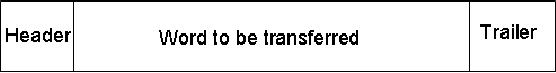
Additional
bits are usually associated
with each packet. These bits
contain
information
about the packet. These additional
bits are of two types:
header and
trailer.
As an example, a packet may have
the form shown
below:
If we use
a 1- bit header, we may have
the following
protocol:
Header = 0, it
means it is a request
Header = 0,
Reply
By
reading these header bits, a
machine becomes able to receive
data or supply data.
To
transfer data by using
packets through hardware is
very difficult. So all the
transfer is
done by
using software. By using
more number of bits, in a header, we can
send more
messages.
For example if n bits are
used as header then 2n is the number of messages
that
can be
transmitted over a network by
using a single header.
For a 2
bit header: we may have 4
types of messages:
Page
374
Last
Modified: 01-Nov-06
Advanced Computer
Architecture-CS501
________________________________________________________
00=
Request
01=
Reply
10=
Acknowledge request
11=
Acknowledge reply
Error
detection
The
trailer can be used for
error detection. In the above
example, a 4 bit checksum can
be
used to
detect any error in the packet.
The errors in the message
could be due to the
long
distance
transmission. If the error is
found in some message, then
this message will be
repeated.
For a reliable data
transmission, bit error rate
should be minimum.
Software
steps for sending a
message:
·
Copy
data to the operating system
buffer.
·
Calculate
the checksum, include in
trailer and star timer.
·
Send
data to the hardware for
transmission.
Software
steps for message
reception:
·
Copy
data to the operating system
buffer.
·
Calculate
the checksum; if same, send
acknowledge and copy data to
the user area
otherwise
discard the message.
Response
of the sender to acknowledgment:
·
If
acknowledgment arrives, release
copy of message from the
system buffer.
·
When
timer expires, resend data
and restart the time.
Performance
Issues
1.
Bandwidth
It is the
maximum rate at which data
could be transmitted through
networks. It is
measured
in bits/sec.
2.
Latency
In a LAN,
latency (or delay) is very
low, but in a WAN, it is significant and
this is
due to
the switches, routers and
other components in the
network
3.
Time of flight
It is the
time for first bit of
the message to arrive at the
receiver including
delays.
Time of
the flight increases as the
distance between the two
machines increases.
4. Transmission
time
The
time for the message to
pass through the network,
not including the time
of
flight.
5.
Transport latency
Transport
latency= time of flight +
transmission time
6.
Sender overhead
Page
375
Last
Modified: 01-Nov-06
Advanced Computer
Architecture-CS501
________________________________________________________
It is the
time for the processor to
inject message in to the
network.
7. Receiver
overhead
It is the
time for the processor to
pull the message from
the network.
8.
Total latency
Total
latency = Sender overhead + Time of
flight + Message size/Bandwidth +
Receiver
overhead
9.
Effective bandwidth
Effective
bandwidth = Message size/Actual
Bandwidth
Actual
bandwidth may be larger than
the effective
bandwidth.
Example#1
Assume a
network with a bandwidth of
1500Mbits/sec. It has a sending
overhead of
100µsec
and a receiving overhead of 120µsec.
Assume two machines
connected together.
It is
required to send a 15,000
byte message from one
machine to the other
(including
header), and
the message format allows
15, 00 bytes in a single
message. Calculate
the
total
latency to send the message
from one machine to another
assuming they are
20m
apart (as
in a SAN). Next, perform the
same calculation but assume
the machines are
700m
apart (as in a LAN). Finally,
assume they are 1000Km apart
(as in a WAN).
Assume
that signals propagate at
66% of the speed of light in
a conductor, and that
the
speed of
light is 300,000Km/sec.
Solution
By using
the assumption, we
get:
Distance
between two machines in
Km
Time of
flight =
--------------------------------------------------
2/3 x
300,000Km/sec
Total
Latency = Sender overhead +
Time of flight + Message
size/bandwidth
+
Receiver overhead
For
SAN:
Total
latency = 100µsec
+
(0.020Km/(2/3 x 300,000Km/sec))
+
15,000bytes/ 1500Mbits/sec
+
120µsec
= 100µsec
+ 0.1µsec + 80µsec +
120µsec
=
300.1µsec
For
LAN
Total
latency = 100µsec
+
(0.7Km/(2/3 x 300,000Km/sec))
+
15,000bytes/ 1500Mbits/sec +
120µsec
= 100µsec
+ 3.5µsec + 80µsec +
120µsec
Page
376
Last
Modified: 01-Nov-06
Advanced Computer
Architecture-CS501
________________________________________________________
=
303.1µsec
For
WAN
Total
latency = 100µsec
+
(1000Km/(2/3 x 300,000Km/sec))
+
15,000bytes/ 1500Mbits/sec
+
120µsec
= 100µsec
+ 5000µsec + 80µsec +
120µsec
=
5300µsec
Effective
bandwidth versus Message
size
Effective
bandwidth is always less
than the raw bandwidth. If
the effective bandwidth
is
closer to
the raw bandwidth, the size
of the message will be larger. If
the message size is
larger
then network will be more
effective.
If large
number of the messages are
present then a queue will be formed, and
the user has
to face
delay. To minimize the
delay, it is better to use
packets of small
size.
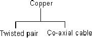
Physical
Media
Twisted
pair does not provide good
quality of transmission and has
less bandwidth. To
get high
performance and larger bandwidth, we
use co-axial cable. For
increased
performance,
better performance, we use
fiber optic cables, which
are usually made of
glass. Data
transmits through the fiber
in the form of light pulses.
Photo diodes and
sensors
are used to produce and
receive electronic pulses.
Page
377
Last
Modified: 01-Nov-06
Table of Contents:
- Computer Architecture, Organization and Design
- Foundations of Computer Architecture, RISC and CISC
- Measures of Performance SRC Features and Instruction Formats
- ISA, Instruction Formats, Coding and Hand Assembly
- Reverse Assembly, SRC in the form of RTL
- RTL to Describe the SRC, Register Transfer using Digital Logic Circuits
- Thinking Process for ISA Design
- Introduction to the ISA of the FALCON-A and Examples
- Behavioral Register Transfer Language for FALCON-A, The EAGLE
- The FALCON-E, Instruction Set Architecture Comparison
- CISC microprocessor:The Motorola MC68000, RISC Architecture:The SPARC
- Design Process, Uni-Bus implementation for the SRC, Structural RTL for the SRC instructions
- Structural RTL Description of the SRC and FALCON-A
- External FALCON-A CPU Interface
- Logic Design for the Uni-bus SRC, Control Signals Generation in SRC
- Control Unit, 2-Bus Implementation of the SRC Data Path
- 3-bus implementation for the SRC, Machine Exceptions, Reset
- SRC Exception Processing Mechanism, Pipelining, Pipeline Design
- Adapting SRC instructions for Pipelined, Control Signals
- SRC, RTL, Data Dependence Distance, Forwarding, Compiler Solution to Hazards
- Data Forwarding Hardware, Superscalar, VLIW Architecture
- Microprogramming, General Microcoded Controller, Horizontal and Vertical Schemes
- I/O Subsystems, Components, Memory Mapped vs Isolated, Serial and Parallel Transfers
- Designing Parallel Input Output Ports, SAD, NUXI, Address Decoder , Delay Interval
- Designing a Parallel Input Port, Memory Mapped Input Output Ports, wrap around, Data Bus Multiplexing
- Programmed Input Output for FALCON-A and SRC
- Programmed Input Output Driver for SRC, Input Output
- Comparison of Interrupt driven Input Output and Polling
- Preparing source files for FALSIM, FALCON-A assembly language techniques
- Nested Interrupts, Interrupt Mask, DMA
- Direct Memory Access - DMA
- Semiconductor Memory vs Hard Disk, Mechanical Delays and Flash Memory
- Hard Drive Technologies
- Arithmetic Logic Shift Unit - ALSU, Radix Conversion, Fixed Point Numbers
- Overflow, Implementations of the adder, Unsigned and Signed Multiplication
- NxN Crossbar Design for Barrel Rotator, IEEE Floating-Point, Addition, Subtraction, Multiplication, Division
- CPU to Memory Interface, Static RAM, One two Dimensional Memory Cells, Matrix and Tree Decoders
- Memory Modules, Read Only Memory, ROM, Cache
- Cache Organization and Functions, Cache Controller Logic, Cache Strategies
- Virtual Memory Organization
- DRAM, Pipelining, Pre-charging and Parallelism, Hit Rate and Miss Rate, Access Time, Cache
- Performance of I/O Subsystems, Server Utilization, Asynchronous I/O and operating system
- Difference between distributed computing and computer networks
- Physical Media, Shared Medium, Switched Medium, Network Topologies, Seven-layer OSI Model