 |
Work Breakdown Structure (WBS) |
| << Characteristics of a High-Quality WBS |
| WBS- Major Steps, WBS Implementation, high level WBS tasks >> |

Software
Project Management
(CS615)
LECTURE
# 35
7.
Work Breakdown Structure
7.5
WBS-
A Mandatory Management
Tool
iv.
Sample
WBS
Sample 1:
These
two graphics illustrate
approaching the WBS as a parts
list or as a
process
list
254
Software
Project Management
(CS615)
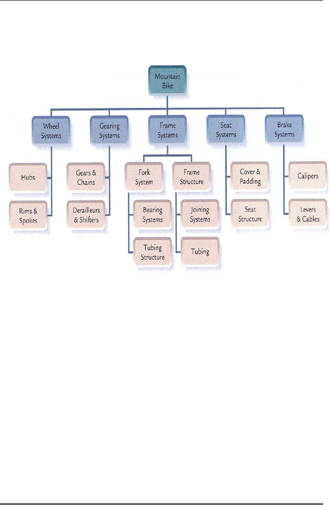
Sample 2:
WBS of
Manufacturing of a Mountain
Bike
255

Software
Project Management
(CS615)
Sample 3:
This
illustrates an example of Ordnance
System WBS
256

Software
Project Management
(CS615)
The
list of activities is often
called a Work Breakdown
Structure (WBS). The goal is
to
integrate
the WBS, the schedule, and
the budget into a written
plan.
The
WBS reflects activities
associated with overall
project management,
requirements,
design,
implementation, transition management,
testing, training, installation,
and
maintenance.
The project manager is responsible
for defining all top
level tasks
associated
with a project and then
further decomposing them as planning
continues.
An
activities list is typically
shown in one of two ways. It can be
shown as an outline or
it can be
graphically presented. Two samples of an
activities list (WBS) are
shown
below.
1.0
MANAGEMENT
1.1
Plan
Project
1.1.1
Develop
Project Plan
1.1.2
Update
Project Plan
1.2
Track
Project
1.2.1
Prepare
status reports
1.2.2
Collect/analyze
project metrics
1.3
Perform
Quality Activities
1.3.1
Prepare
QA Plan
1.3.2
Conduct
Reviews
1.3.3
Conduct
Audits
1.4
Perform
Configuration Management
1.4.1
Prepare
CM Plan
1.4.2
Develop
Project Library
1.4.3
Manage
Change Board
1.4.4
Maintain
Configuration Items
2.0
DESIGN
2.1
Prepare
Preliminary Design
2.1.1
Develop
Enterprise Architecture
2.1.2
Prepare
Data Flow Diagrams
2.1.3
Prepare
Logical Data Model
2.2
Prepare
Detailed Design
2.2.1
Prepare
Physical Data Model
2.2.2
Prepare
Data Dictionary
2.3
Document
Design
2.3.1
Develop
Design Specification
2.4
Review
Design
257
Software
Project Management
(CS615)
3.0
DEVELOPMENT/INTEGRATION
3.1
Develop
Software
3.1.1
Develop
Server Application
3.1.2
Develop
User Interface
3.1.3
Develop
XYZ Interface
3.2
Procure
Hardware
3.2.1
Procure
Server
3.2.2
Procure
Workstations
3.3
Procure
Software Packages
3.3.1
Procure
Database
3.3.2
Procure
User Interface Building
Tool
3.3.3
Procure
Operating System
3.4
Perform
Integration Testing
3.5
Convert
Data
3.5.1
Develop
Conversion Plan
3.6
Develop
User Manual
3.7
Transition
Management
4.0
ACCEPTANCE TESTING
4.1
Plan
Acceptance Test
4.2
Conduct
Acceptance Test
4.3
Develop
Test Report
5.0
INSTALLATION
5.1
Develop
Installation Plan
5.2
Site
Preparation
5.3
Install
at Locations
5.3.1
Headquarters
5.3.2
Site
1
6.0
MAINTENANCE
6.1
Hardware
Maintenance
6.2
Software
Maintenance
258
Software
Project Management
(CS615)
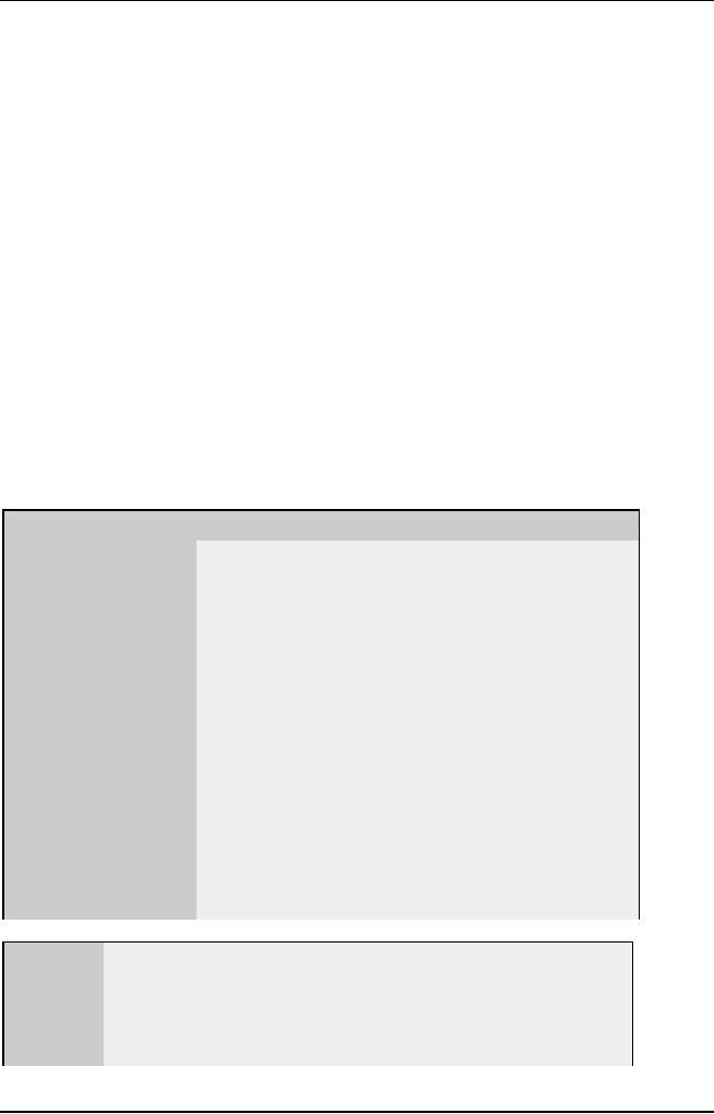
Sample
4:
Sometimes, instead of depicting the WBS
as an outline, it is shown
graphically,
as below:
WBS
Work
Breakdown
Schedule
(WBS)
Development/
Acceptance
Management
Design
Installation
Maintenance
Integration
Testing
Prepare
Develop
Plan
Acceptance
Develop
Hardware
Preliminary
Plan
Project
Software
Test
Installation
Plan
Maintenance
Design
Develop
Enterprise
Develop
Server
Develop
Project Plan
Conduct
Software
Architecture
Application
Site
Preparation
Update
Project Plan
Acceptance
Test
Maintenance
Prepare
Data
Develop
User
Flow
Diagrams
Interface
Track
Project
Develop
Test
Install
at
Develop
XYZ
Prepare
Logical
Report
Locations
Interface
Data
Model
Prepare
status report
Procure
Headquarters
Prepare
Detailed
Collect/analyze
Hardware
project
metrics
Design
Site
One
Procure
Server
Prepare
Physical
Perform
Quality
Procure
Workstations
Data
Model
Activities
Prepare
Data
Procure
Software
Dictionary
Prepare
QA Plan
Packages
Conduct
Reviews
Document
Procure
Databases
Conduct
Audits
Design
Procure
User Interface
Building
Tool
Develop
Design
Perform
CM
Procure
Operating
Specification
System
Prepare
CM Plan
Perform
Review
Design
Develop
Project Library
Integration
Testing
Manage
Change Board
Maintain
Configuration
Items
Convert
Data
Develop
Conversation
Plan
Develop
User
Manual
Transition
Management
259
Software
Project Management
(CS615)
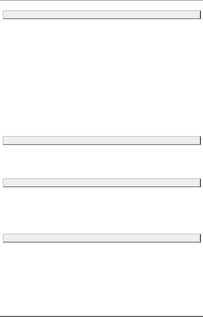
Sample
4:
Chart WBS
00
Retail
Web
Site
4.
5.0
1.0
2.
3.
0
0
0
Project
Requiremen
Design
and
Site
Software
Managemen
ts
Analysis
Development
HTML
Graphics
and
Content
Backend
Design
Interface
Creation
Software
4.4
4.3
4.
4.
1
2
Database
Security
Catalog
Transaction
Implementat
Subsystems
Engine
Processing
4.2.4
4.2.1
4.2.2
4.2.3
Sample
WBS - Outline
Example-1
0.0
Retail Web Site
1.0
Project Management
2.0
Requirements Gathering
3.0
Analysis & Design
4.0
Site Software Development
4.1
HTML Design and Creation
4.2
Backend Software
4.2.1
Database Implementation
4.2.2
Middleware Development
4.2.3
Security Subsystems
4.2.4
Catalog Engine
4.2.5
Transaction Processing
4.3
Graphics and Interface
4.4
Content Creation
5.0
Testing and Production
260

Software
Project Management
(CS615)
Sample
WBS - Outline
Example-2
1.10
MANAGEMENT
1.1
Plan
Project
1.1.1
Develop Project
Plan
1.1.2
Update Project
Plan
1.2
Track
Project
1.2.1
Prepare status reports
1.2.2
Collect/analyze project
metrics
1.3
Perform
Quality Activities
1.3.1
Prepare QA Plan
1.3.2
Conduct Reviews
1.3.3
Conduct Audits
1.4
Perform
Configuration Management
1.4.1
Prepare CM Plan
1.4.2
Develop Project
Library
1.4.3
Manage Change Board
1.4.4
Maintain Configuration
Items
2.0
DESIGN
2.1
Prepare
Preliminary Design
2.1.1
Develop Enterprise
Architecture
2.1.2
Prepare Data Flow
Diagrams
2.1.3
Prepare Logical Data
Model
2.2
Prepare
Detailed Design
2.2.1
Prepare Physical Data
Model
2.2.2
Prepare Data Dictionary
2.3
Document
Design
2.3.1
Develop Design
Specification
2.4
Review
Design
3.0
DEVELOPMENT/INTEGRATION
3.1
Develop
Software
3.1.1
Develop Server
Application
3.1.2
Develop User
Interface
3.1.3
Develop XYZ Interface
3.2
Procure
Hardware
3.2.1
Procure Server
3.2.2
Procure Workstations
3.3
Procure
Software Packages
3.3.1
Procure Database
3.3.2
Procure User Interface
Building Tool
3.3.3
Procure Operating
System
3.4
Perform
Integration Testing
3.5
Convert
Data
261
Software
Project Management
(CS615)
3.5.1
Develop Conversion
Plan
3.6
Develop
User Manual
3.7
Transition
Management
4.0
ACCEPTANCE
TESTING
4.1
Plan
Acceptance Test
4.2
Conduct
Acceptance Test
4.3
Develop
Test Report
5.0
INSTALLATION
5.1
Develop
Installation Plan
5.2
Site
Preparation
5.3
Install
at Locations
5.3.1
Headquarters
5.3.2
Site 1
6.0
MAINTENANCE
6.1
Hardware
Maintenance
6.2
Software
Maintenance
Sample
WBS - Outline
Example-3
Step
Description
Estimate
1.
Preparation
TBD
1.1.
Developer
orientation
1.2.
Requirements
gathering
TBD
1.2.A.
Use
Cases
TBD
1.2.B.
Changes
to data model
TBD
1.2.C.
Non-functional
requirements
TBD
1.2.D.
Requirements
validation
1.3.
Design
TBD
1.3.A.
Software
architecture
TBD
1.3.B.
User
interface design
TBD
1.4.
Development
tools
2.
Construction
2.1.A.
System
implementation
TBD
2.1.A.1
Unit
tests
TBD
2.1.A.2
Production
code
262
Software
Project Management
(CS615)
TBD
2.1.
A.3.
Integrate
Components
(mostly
done during component
implementation)
TBD
2.1.B.
Maintenance
documentation
TBD
2.1.C.
User
documentation
3.
Quality
assurance
TBD
3.1.
Fixing
defects reported by
users
3.2.
Testing
TBD
3.2.
D.1.
Test
planning
TBD
3.2.
D.2.
Test
implementation
TBD
3.2.
D.3.
Test
execution
TBD
3.3.
Reviews
of design and code
TBD
3.4.
Fixing
defects found by testing and
review
4.
Transition
TBD
4.A.
Release
packaging
TBD
4.B.
Documentation
for other groups
5.
Reflection
TBD
5.1.
Postmortem
report
Total
fixed costs
TBD
·
Tasks
shown as blue are fixed
costs of the project. These
should be
estimated
soon.
·
Tasks
shown as black are
proportional to the size of the
requirements. A
more
detailed work breakdown
structure will be produced
for these tasks
when
the requirements are better
known.
·
Tasks
shown as red depend on the
defect rate in the delivered
code. These
will
be estimated after 12 months
experience.
TIP: Label each step uniquely
to show its position in the WBS, e.g.,
Step 1.1.4.A. Use numbers for
steps that you intend to do in
sequence, and use letters for
steps that you intend to do in parallel.
E.g., Step 1.1 comes before
Steps 1.2.A and 1.2.B, but those two
steps may be done in
parallel, and Step 1.3 will be done after all 1.2.*
steps have been finished.
Don't worry about renumbering if you delete
a step.
263

Software
Project Management
(CS615)
7.7
WBS-
Major Steps
a)
Project Decomposition
Many
complex objects can be viewed as a
collection of numerous simpler
objects.
An
appropriate example would be a
complex chemical compound
that is formed
by
various molecules, each of
which is formed by combining
various atoms. The
atom,
though itself divisible, can be
regarded as the smallest
particle of a
chemical
substance.
In a
similar way, a complex
project can be divided into
simpler components.
While
the full project may be
difficult to manage, each component will
be easier
to
handle. Software projects can be
decomposed into smaller
components in order
to
provide better estimates of
the amount of work involved,
or in order to monitor
the
activities of the various
development teams.
The
decomposition of a software project is
one of the software project
manager's
first
tasks. However, the method of
decomposition may differ,
depending on the
project
manager's actual objective. A
functional decomposition of a project
may
not be
the same as design decomposition. A
functional decomposition divides
the
project
into its basic components
from a user's perspective,
while design
decomposition
divides a project into its
basic programming components
or
modules.
Intuitively,
it would not appear reasonable to
attempt to identify all
project
components
in a single step. Clearly, an
iterative procedure that
would gradually
provide
more detail would be easier
to use. Iterative methods of
this kind are
called
stepwise refinement, as the decomposition
is further refined in
each
succeeding
step.
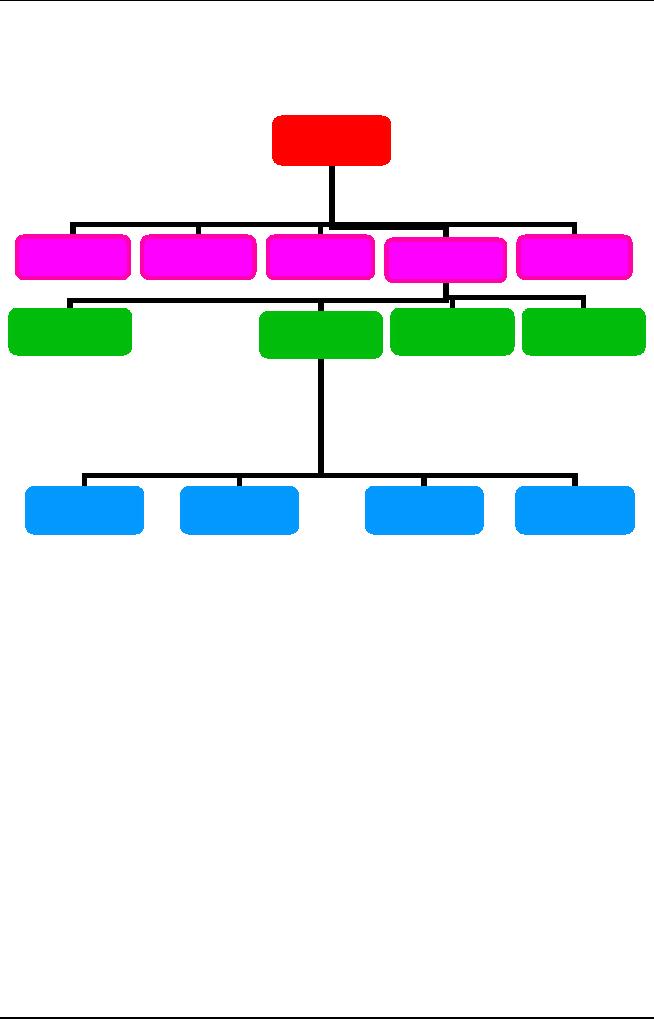
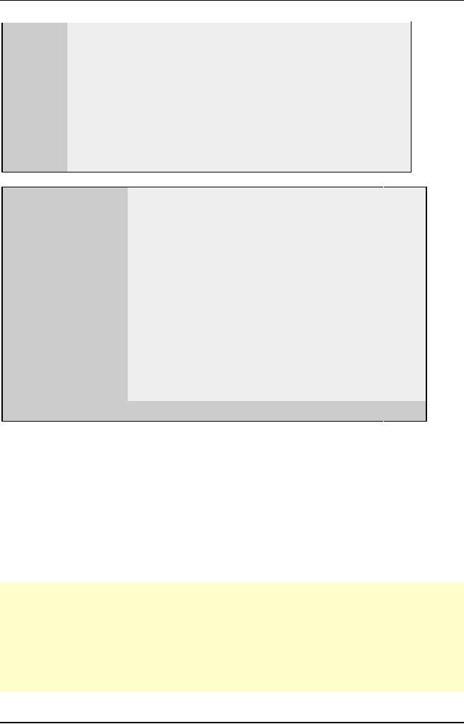
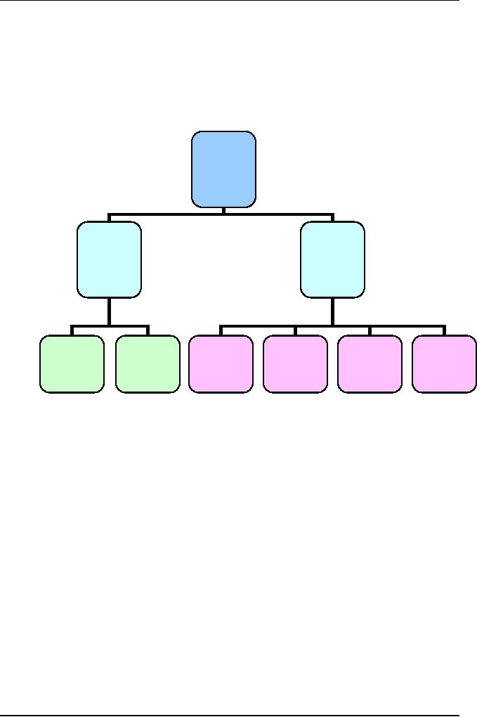
Figure 1
presents a general illustration of
stepwise refinement. The system
is
initially
divided into three top
level components. In turn
each top level
component
is
further divided into lower
level components, and so forth,
until the lowest
decomposition
level is reached.
In a stepwise
decomposition of a project, each
component decomposes into
the
components
directly below it, so that
each step of the
decomposition describes
the
full
system, but at a different
level of detail. In Fig.1,
components 1, 2 and 3
comprise
the complete system. For
more detail we take the next
decomposition
step, and
find that components 1.1,
1.2, 2.1, 2.2, 2.3,
3.1 and 3.2 now
represent
the
whole system.
264
Software
Project Management
(CS615)
System
System
Component
Component
Component
1
2
3
1.1
1.2
2.1
2.2
2.3
3.1
3.2
2.1.1
2.2.1
2.2.2
2.3.1
2.3.2
2.1.2
2.2.3
Figure
1: Software
decomposition by stepwise
refinement
A stepwise
refinement diagram looks
similar to a hierarchical system
chart.
However,
it is important to understand that
stepwise refinement is basically
different
because the diagram's building
blocks are different A
hierarchical
system
diagram describes the
hierarchical relationship between
components, so
that
each component in the
diagram actually corresponds to a real
component in
the
system. However, in a stepwise refinement
diagram, a higher level
component
is only a
name conveniently given to a group of
real components that
appear
below
it.
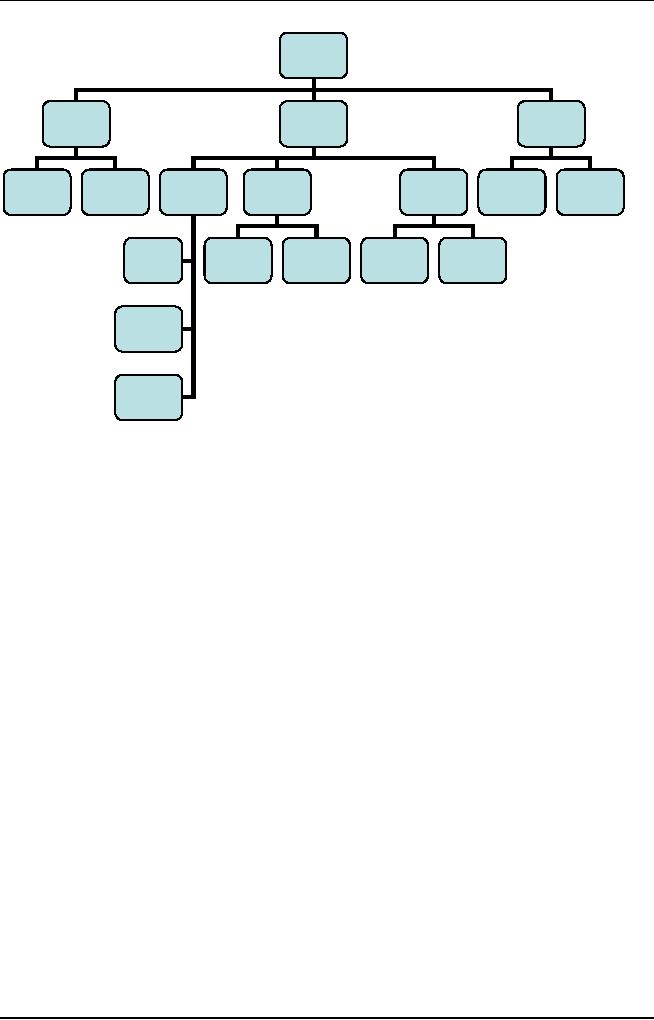
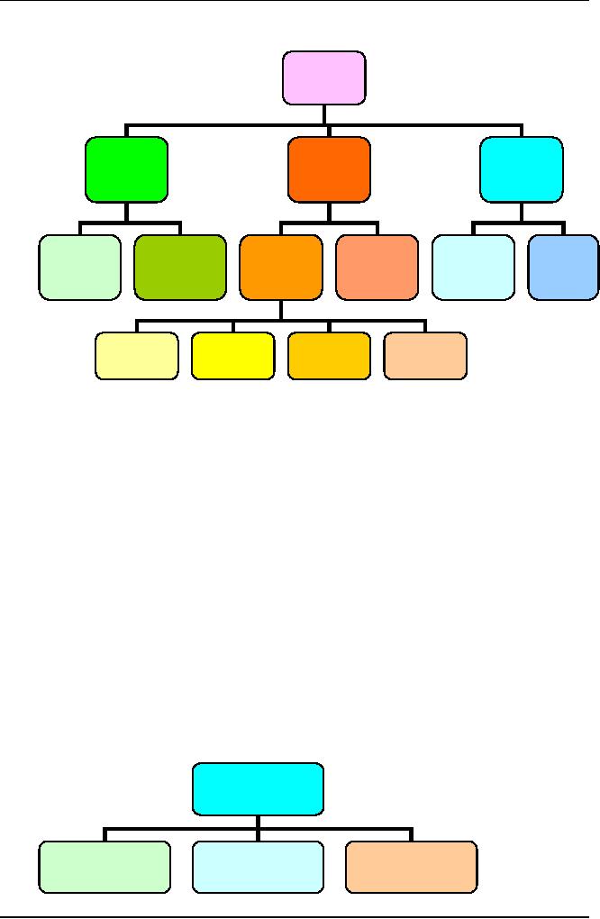
In Fig.
2(a) the Controlled access
system software has five
low level software
components:
Visitor
identification, Door lock-control,
Access file-manager, Illegal
access
identification
and Alarm activation. Each of
these five modules may
correspond
to an
actual software module1. The two high
level components, Access
control
and Alarm
system, do not exist as
actual software modules, and
only appear as
names
given to the two groups of
lower level
components.
Figure
2(b) describes the same
Controlled access system
software, but this time
it
is
represented as a hierarchical chart.
Here, each component in the
diagram
represents
a real software
component.
265
Software
Project Management
(CS615)
The
System executive main Loop
component calls three other
components:
Visitor
identification, Door lock
control and Alarm
activation: The
Visitor
identification
component calls two
components: Illegal
access identification and
Access
file manager.
Figure
2: (a)
Decomposition
of high level components
into low level components;
(b) a
hierarchical
structure chart
Controlled
(a)
Access
system
Software
Access
Alarm
Control
System
Illegal
Visitor
Door
lock
Access
Access
Alarm
File
Identification
Control
Identification
Activation
Manager
(b)
System
Executive
Main
loop
Visitor
Door
lock
Alarm
Identification
Control
Activation
Illegal
Access
Access
File
Identification
Manager
266

Software
Project Management
(CS615)
Just like
any other large complex
task, the development of a
software project is
more
easily managed with the
divide and conquer approach.
Stepwise
refinement, when applied to a
software project, produces all
the low
level
work tasks and
includes
development
tasks
managerial
tasks
support
tasks and
administrative
tasks
The
WBS list of project tasks is
derived from the project's
statement of work
(the
SOW)
that defines the scope of
the project. The SOW is
usually prepared
before
the
official launching of the
project, and is often part of
the project contract
between
the customer and the
developer.
For
internal projects, when an
organization is funding its
own development work,
the
SOW becomes synonymous with
the Project definition
specification or a
similar
document that defines the
scope of work for the
software project manager.
b)
Functional Decomposition
The
functional decomposition of a software
project is a division of the
system into
its
operational components as they
are seen by the user.
Functional decomposition
is part
of the requirements phase of a
project. The objective of
this phase is to
define
air the characteristics of
the system from the
user's perspective.
Let us
consider an automatic bank
teller system. The ability
to communicate on-
line
between the remote automatic
tellers and the bank's central
computer in order
to
provide updated account information is a
functional characteristic or
the
system.
This will
usually be defined during
the requirements phase of
the development
cycle.
However, the method of
transmission between the
automatic teller and
the
central
computer is not a functional
characteristic of the system, as
this is internal
to the
design and implementation of the system
and is not apparent to the
user.
The
method of transmission, including
the communications protocol, will
usually
be
defined during the design
phase of the development of
the system.
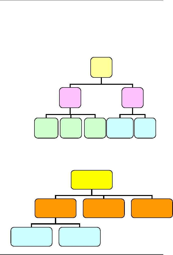
Figure 3
presents an example of the
functional decomposition of an
automatic
bank
teller system into lower
levels of functional components. In
Fig. 3 we have
determined
that there will be a customer
data base, which could be
viewed as a
design
decision.
267
Software
Project Management
(CS615)
This is
unavoidable. The functional
decomposition is rarely completely
devoid of
all
design considerations. As we will see,
the functional decomposition is
often a
starting
point for the initial design
of the system.
Automatic
Bank
teller
System
Automatic
Central
Teller
Computer
Services
Services
Central
Teller
User
Computer
Machine
Report
Customer
Operator
Query
and
Interface
Data
base
Services
Generator
Services
Update
Functions
Manager
Figure
3: Automatic
teller system - functional
decomposition diagram
Just as
the requirements phase
precedes the design phase, so
the functional
decomposition
of a software system will usually
precede the design
decomposition.
The
functional decomposition will often
provide much of the
information
necessary
for the subsequent division of
the system into the
implementation
components.
In fact,
the functional decomposition is
often a good place to start when
designing
a
software system, as the
major functional components of a
system will often
correspond
to the initial division of
the system into subsystems or
high level
components.
268

Software
Project Management
(CS615)
c)
Design Decomposition
The
design decomposition of a software system
is a division of the system
into
lower
level components that
coincide with the actual
software components of
the
system.
In a full design decomposition of a software
system, the lowest
components
correspond to programming modules
(usually procedures,
subroutines
or program functions).
The
work breakdown structure
(WBS) is the decomposition of a
software project
into
low level work
tasks.
An
important point to remember is
that in design decomposition, only
the lower
level
components are actually
implemented. Higher level
components represent a
group of
lower level
components.
Design
decomposition basically produces two
types of system
component:
·
high
level components and
·
low
level modules
Different
software development standards
use different terminology to
identify
the
various levels of
decomposition.
Figure 4
presents an example of the design
decomposition of an automatic
bank
teller
system into lower levels of
design components. On the third
level, the
Automatic
teller component decomposes
into the Hardware
interfaces, and the
Teller
logic. The next level
may then decompose the
Hardware interfaces into
the
Keyboard
driver, the Display driver,
the Printer, driver and the
Beeper. At this
level,
these drivers may represent
actual software
modules.
269
Software
Project Management
(CS615)
Automatic
Bank
teller
System
Wide
area
Automatic
Central
Network
Teller
Computer
Interface
Teller
Central
Customer
Teller
Communications
Computer
Hardware
Teller
Data
base
Interface
Communications
Interface
Interfaces
Logic
Manager
Logic
Interface
Keyboard
Display
Printer
Beeper
Driver
Driver
Driver
Driver
Figure
4: Automatic
teller system -design
decomposition diagram
A fully
decomposed system, with all
its low level components, is
not always easy
to grasp.
This is especially true
during the presentation of
the system at a
project
review,
when the system needs to be
quickly understood by people who
have not
been
involved in its design.
On such
occasions, the stepwise refinement
technique is a convenient method
for
gradually
presenting progressive detail by
initially showing the
first
decomposition
level, and then slowly
revealing subsequent levels. This
is
demonstrated in
figure 5.
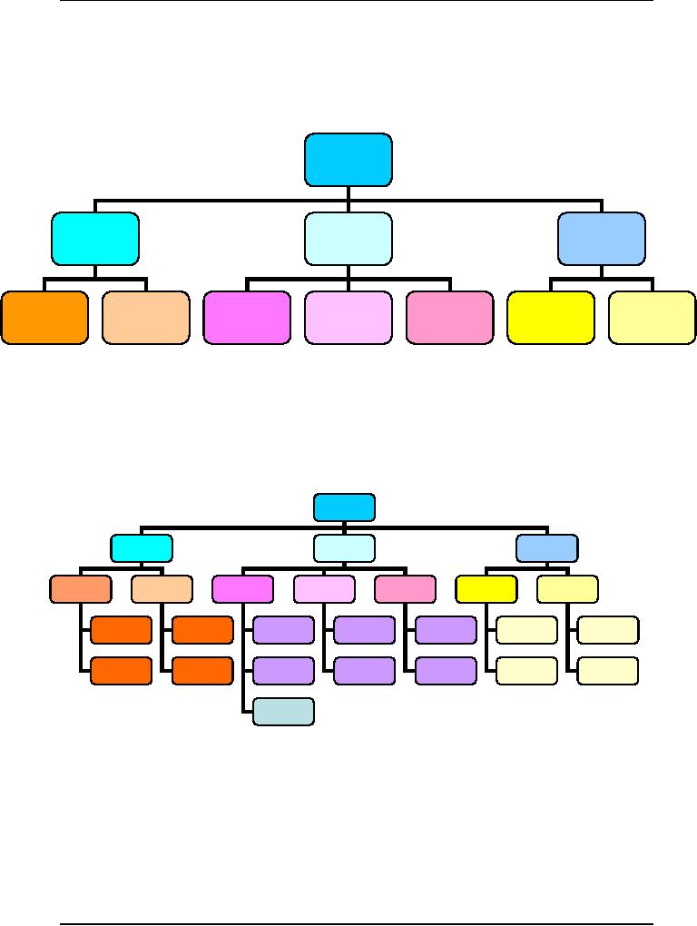
At a
convenient intermediate decomposition
step we can divide the design in
two:
the
upper levels and the lower
levels. This is used
particularly when the
design
phase is
implemented in two distinct
stages: top level design and
detailed design
(see
Fig.5).
System
Component
Component
Component
3
1
2
270
Software
Project Management
(CS615)
Initial
top level decomposition
System
Component
Component
Component
2
3
1
1.1
1.2
2.1
2.2
2.3
3.1
3.2
Intermediate
level decomposition top level
design
System
Component
Component
Component
1
2
3
1.1
1.2
2.1
2.2
2.3
3.1
3.2
Low
level decomposition detailed
design
Figure
5: Software
decomposition by stepwise
refinement
271

Software
Project Management
(CS615)
d)
Develop Project
Tasks
WBS
tasks are developed by
asking, "What tasks need to
be done to accomplish
the
project objective?" The
choice of WBS structure is
subjective and reflects
the
preferences and
judgment of the project
manager.
As levels
of the WBS become lower,
the scope, complexity, and cost of
each
subtask
become smaller. The lowest
level tasks, or work packages,
are
independent,
manageable units that are
planned, budgeted, scheduled, and
controlled
on their own.
As
efforts of similar scope and
type are planned, the
basic WBS tasks
remain
fairly
similar, but each project
requires a specific set of
tasks that address
the
uniqueness
of the project's requirements.
Certain top level elements,
such as
project
management, are included in
the WBS of every project,
regardless of its
type,
size, or complexity. Other
items, like installation,
may not apply to
every
project.
The
initially developed WBS
evolves over the course of
the planning. It is
highly
probable
that it will look quite
different as the scheduling,
estimation, and
resource
allocation portions of the
plan are completed.
One of
the difficult parts of talking
about IT projects generically is
the wide range
of such
projects. Typically, in a small
project, there is a single
project
development
phase.
In large
or complex systems, however, there
are often multiple
development
phases,
where different functional
requirements are met.
Sometimes
these phases are driven by
the need to achieve certain
levels of
functionality
prior to the availability of
the complete system.
Other
times, the phases are
defined to partition the
development effort and to
reduce
the risks associated with
larger project
efforts.
272
Table of Contents:
- Introduction & Fundamentals
- Goals of Project management
- Project Dimensions, Software Development Lifecycle
- Cost Management, Project vs. Program Management, Project Success
- Project Managements nine Knowledge Areas
- Team leader, Project Organization, Organizational structure
- Project Execution Fundamentals Tracking
- Organizational Issues and Project Management
- Managing Processes: Project Plan, Managing Quality, Project Execution, Project Initiation
- Project Execution: Product Implementation, Project Closedown
- Problems in Software Projects, Process- related Problems
- Product-related Problems, Technology-related problems
- Requirements Management, Requirements analysis
- Requirements Elicitation for Software
- The Software Requirements Specification
- Attributes of Software Design, Key Features of Design
- Software Configuration Management Vs Software Maintenance
- Quality Assurance Management, Quality Factors
- Software Quality Assurance Activities
- Software Process, PM Process Groups, Links, PM Phase interactions
- Initiating Process: Inputs, Outputs, Tools and Techniques
- Planning Process Tasks, Executing Process Tasks, Controlling Process Tasks
- Project Planning Objectives, Primary Planning Steps
- Tools and Techniques for SDP, Outputs from SDP, SDP Execution
- PLANNING: Elements of SDP
- Life cycle Models: Spiral Model, Statement of Requirement, Data Item Descriptions
- Organizational Systems
- ORGANIZATIONAL PLANNING, Organizational Management Tools
- Estimation - Concepts
- Decomposition Techniques, Estimation Tools
- Estimation Tools
- Work Breakdown Structure
- WBS- A Mandatory Management Tool
- Characteristics of a High-Quality WBS
- Work Breakdown Structure (WBS)
- WBS- Major Steps, WBS Implementation, high level WBS tasks
- Schedule: Scheduling Fundamentals
- Scheduling Tools: GANTT CHARTS, PERT, CPM
- Risk and Change Management: Risk Management Concepts
- Risk & Change Management Concepts
- Risk Management Process
- Quality Concept, Producing quality software, Quality Control
- Managing Tasks in Microsoft Project 2000
- Commissioning & Migration