 |
TEMPLATE BASED SYNTHESISSynthesis, Mechanism and Pathway |
| << SOL-GEL TECHNIQUES:DEFINITIONS, GENERAL MECHANISM, INORGANIC ROUTE |
| MICROEMULSION TECHNIQUES:Significance of Packing Parameter >> |
Chapter
- 6
TEMPLATE
BASED SYNTHESIS
B.Kuppan
INTRODUCTION
To
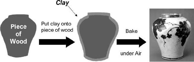
make a jar, a piece of wood of
the desired shape is first
fabricated, and layer of
clay
is applied to the wood. Heat
treatment of the clay/wood
composite at high
temperature
generates a ceramic jar.
During the heat treatment,
clay is transformed to
a
ceramic material and the
wood is burned off leaving
the empty space in
the
resulting
jar. When this process is
scale down to nanometer
regime, it is basically
the
template
synthesis process
[1].
Fig.
6.1. Schematic representation of
template synthesis (reproduced
from ref. 1)
One
class of templates are
surfactants that are used to
produce mesoporous materials.
It
is true to say one of the
most exciting discoveries in the
field of material
synthesis
over
the last 15 years is the
formation of mesoporous silicate and
alumino silicate
molecular
sieves with liquid crystal
templates. This family
materials generally
called
as
M41S family (MCM-41, MCM-48
and MCM-50) [2].
These
M41S family
materials
can be prepared by using cationic
surfactants as the templates, and
other
kind
of mesoporous materials also can be prepared by
using non-ionic surfactants
as
the
templates. These family materials
are called as SBA-n family
[3].
The
above mentioned mesoporous molecular
sieves also can be used as
templates
to
prepare ordered mesoporous carbon by
using sucrose as the carbon
precursors.
These
mesoporous silicates, aluminosilicates and mesoporous
carbon materials are
6.2
Template
Based Synthesis
more
important in the field of
catalysis because of its
high surface area, narrow
pore
size
distribution and large number of
surface functional groups.
The surfaces of these
materials
can also be tuned depending on the
applications.
Another
kind of template based
synthesis is to prepare freestanding,
non-oriented
and
oriented nanowires, nanorods or
nanotubes. The fabrication of
metal nanowires
had
potential applications in the
microelectronic industry and in
particular, for
interconnection
in electronic circuits. The
procedure is based on metal
displacement
reaction
leading to the growth of
metal nanowires into the
pores. The galvanic
displacement
reaction for the synthesis
of core /sheet nanostructured materials
has
been
investigated in the literature
[4].
Nanostructured
materials have attracted
much interest because of
their unique
properties.
In fact, due to their structure
features and size effects, they
show physical
properties
that are different from
bulk materials. Many methods
have been developed
for
the fabrication of nanowires.
Among these methods template
synthesis is
considered
as quite useful, because it can be
used for the preparation of
different
types
of nanostructures. The high
order degree of porous
structure of anodic
alumina
membrane
(AAM) (consisting in a close packed array
of columnar hexagonal
cells,
each
containing a central cylindrical pore
normal to the surface),
makes it an ideal
template
for the fabrication of
nanostructured materials, suitable
for applications in
optoelectronics,
sensors, magnetic memories and
electronic circuits
[5].
Synthesis,
Mechanism and Pathway
A
large number of studies have
been carried out to
investigate the formation
and
assembly
of mesostructures on the basis of
surfactant self-assembly. The
initial liquid
crystal
template mechanism first
proposed by Mobil's scientists is
essentially always
"true"
because the pathways
basically include almost all
possibilities. Two main
pathways
that is cooperative self
assembly and "true" liquid
crystal templating
process,
seems to be effective in the
synthesis of ordered
mesostructures.
Surfactants
for the formation of
templates
The
term surfactant is a blend of
"surface acting agent"
surfactants are
usually
organic
compounds that are
amphophilic in nature. Amphophilic
means they contain
Synthetic
Strategies in Chemistry
6.3
both
hydrophobic groups (tails) and
hydrophilic groups (heads). Therefore
they are
soluble
in both organic solvents and
water.
Generally
a clear homogeneous solution of
surfactants in water is required to
get
ordered
mesostructures. Frequently used
surfactants can be classified into
cationic,
anionic
and non-ionic surfactants.
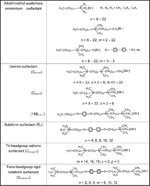
Table
6.1. Cationic
surfactants
(Reproduced
from ref.7)
6.4
Template
Based Synthesis
Quaternary
cationic surfactants, CnH2n+1N (CH3)3Br
(n = 8-22), are generally
efficient
for
the synthesis of ordered mesoporous
silicate materials. Commercially
available
CTAB
(cetyltrimethylammonium bromide) is often
used. Gemini
surfactants,
multiheadgroup
surfactants, and recently reported
cationic fluorinated surfactants
can
also
be used as templates to prepare
various mesostructures. Frequently
used cationic
quaternary
ammonium surfactants are
shown in the table
below
First
reports of mesoporous silica from
Mobil's company, cationic
surfactants
were
used as structure directing
agents (SDAs). Cationic
surfactants have
excellent
solubility,
have high critical micelle
temperature (CMT) values and can be
widely
used
in acidic and basic media. But
they are toxic and
expensive.
Anionic
surfactants include carboxilates,
sulphates, sulfonates, and
phosphates;
recently
a kind of lab-made anionic
surfactant terminal carboxylic
acids is used to
template
the synthesis of mesoporous silicas
with the assistance of
aminosilanes or
quaternary
aminosilanes
such
as
3-aminoprpoyltrimethoxysilane
(APS)
N-
trimethoxylsilylpropyl-N,
N, N-trimethylammonium chloride (TMAPS)
as co-
structure
directing agents
(CSDAs).
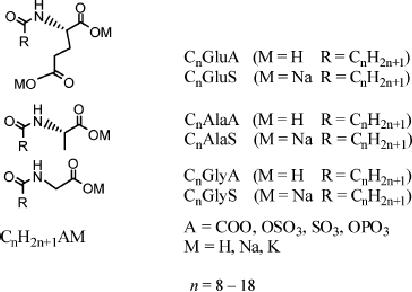
Anionic
surfactants
Fig.
6.2. Representation of anionic
surfactants (reproduced from
ref. 7)
Synthetic
Strategies in Chemistry
6.5
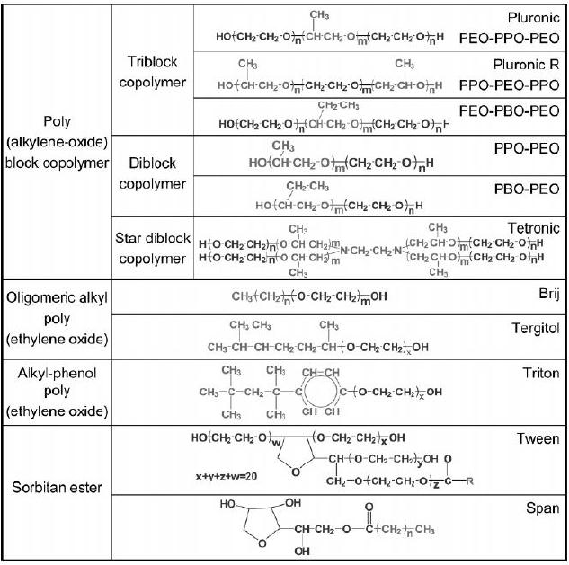
Table
6.2. Non-ionic surfactants
(reproduced from ref.
7)
Non-ionic
surfactants are available in a
wide variety of different
chemical structures.
They
are widely used in industry
because of attractive characteristics
like low price,
nontoxicity,
and biodegradability. In addition the
self assembling of
non-ionic
surfactants
products mesophase with
different geometries and arrangements.
They
become
more and more popular and
powerful in the syntheses of mesoporous
solids.
The
syntheses that largely promote
the development of mesoporous materials
are
simple
and reproducible. A family of mesoporous
silica materials has been
prepared
with
various mesoporous packing symmetries and
well defined pore
connectivity.
6.6
Template
Based Synthesis
Cooperative
Self-Assembly of Surfactant and
Silica Source to Form
Mesostructure
This
pathway is established on the basis of
the interaction between the
silicates
surfactants
to from inorganic-organic mesostructure
composites.
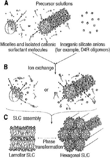
Cooperative
Self-Assembly Mechanism
Fig.
6.3. schematic diagram of
the co-operative self
assembly of silicate-surfactant
mesophase.
(reproduced from ref.
6)
A
layer to hexagonal mechanism
(folded sheet mechanism) was
postulated by Kuroda
and
co-workers, according to which
the mesostructure is created
from a layer
kanemite
precursors. Silicate polyanions
such as silicate oligomers
interact with
positively
charged groups in cationic surfactants
driven by Coulomb forces.
The
silicate
species at the interface
polymerized and cross-link and further
change the
Synthetic
Strategies in Chemistry
6.7
charge
density of the inorganic
layers. With the proceeding of
the reaction, the
arrangement
of the surfactants and the charge
density between inorganic and
organic
species
influence each other. Hence
the compositions of the
inorganic-organic
hybrids
differ to some degree. It is
the matching of charge density at
the
surfactants/inorganic
species interfaces that
govern the assembly process.
The final
mesosphere
is the ordered 3D arrangement with
the lowest interface energy.
The
transformation
of the isotropic micellar
solutions of CTAB into
hexagonal or lamellar
phase
when mixed with anionic
silicate oligomers in highly
alkaline solutions
were
indeed
detected through a combination of
correlated solution state
2H,
13
29
C,
and
Si
nuclear
magnetic resonance (NMR)
spectroscopy, small angle
x-ray scattering
(SAXS),
and polarized optical microscopic
measurements. The mechanism in
different
surfactant systems has been
studied using NMR
technique.
This
cooperative formation mechanism in
non-ionic surfactant system
was
investigated
by in-situ
techniques.
Goldfarb and co-workers investigated
the
formation
mechanism of mesoporous silica SBA-15,
which are templated by
triblock
copolymer
P123 (EO20PO20EO20)
by
using direct imaging and
freeze-fracture
replication
cryo-TEM techniques, in
situ electron
paramagnetic resonance (EPR)
spectroscopy,
and electron spin-echo envelope
modulation (ESEEM)
experiments.
They
found a continuous transformation
from speriodial micelles
into threadlike
micelles.
Bundles were then formed
with dimension that are
similar to those found in
the
final materials. The
elongation of micelles in a consequence of
the reduction of
polarity
and water contact within the
micelles due to the adsorption
and
polymerization
of silicate species. Before
the hydrothermal treatment,
the majority of
PEO
chains insert into silicate
frameworks, which generates
micropores after
removal
of
templates. Moreover they
found that the extent of
the PEO chains located
within
the
silica micropores depended on
the hydrothermal aging
temperature and Si/P123
molar
ratio. The formation
dynamics of SBA-15 studied by
Flodstrom et al. on
the
basis
of time-resolved in
situ 1H NMR and TEM
investigations. They observed
four
stages
during the cooperative
assembly, which are the
adsorption of silicates on
globular
micelles, the association of globular
micelles into floes, the
precipitation of
floes,
and the micelle-micelle coalescence.
Khodakov et al. proposed a
structure with
6.8
Template
Based Synthesis
a
hydrophobic PPO core and a PEO water
silicate corona in the
first stage. The
cylindrical
micelles pack into the
domains. At the same time,
solvents are replaced by
condensed
silicate species.
These
mechanisms consider the
interactions on the surfactants/inorganic
species
interfaces.
Monnier and Huo et al. gave a
formula of the free energy
in the whole
process.
G=
Ginter
+
Gwall
+
Gintra
+
Gsol
In
which
Ginter
associated
with interaction between the
inorganic walls and
Gwall
is the
structural free energy for
the inorganic
frameworks,
surfactant
micelles,
Gintra
is the
van der Waals force and
conformational energy of the
surfactant, and
Gsol
is the
chemical potential associated
with the species in solution
phase.
Gsol
can be
For
surfactant-templating assembly
mesostructured silicates,
regarded
as a constant in a given solution
system. Therefore, the key
factor is the
interaction
between surfactant and inorganic
species, such as the
matching of charge
density.
The more negative
Ginter
is, the
more easily the assembly
process can be
proceeded.
Elaborate
investigations on mesoporous materials
have been focused on
understanding
and utilizing the inorganic-organic
interactions. Table 6.3
lists the
main
synthesis routes and the
corresponding surfactants and classical
products.
Stucky
and co-workers proposed four
general synthetic routes,
which are S+I-,
S-
I+,
S+X-I+, and S-X+I- (S+ = surfactant cations, S- = surfactant anions, I+ = inorganic
precursors
cations, I- = inorganic precursors anions,
X+ = cationic counter ions,
and
X- =
anionic counterions). To yield mesoporous
materials, it is important to adjust
the
chemistry
of the surfactants headgroups, which can
fit the requirement of
the
inorganic
components. Under basic
conditions, silicate anions
(I-)
match with the
surfactant
cations (S+)
through Coulomb forces (S+I-).
The assembly of the
polyacid
anions
and surfactant cations to "salt"-like
mesostructures also belongs to S+I-
interaction.
In contrast to this, one of the
examples of S+I- interaction occurs
between
cationic
keggin ion (Al137+) and anionic surfactants
like dodecyl
benzenesulfonate
salt.
Synthetic
Strategies in Chemistry
6.9
The
organic-inorganic assembly of surfactants
and inorganic precursors with
the same
charge
is also possible. However, counter ion is
necessary. For example, in
the
syntheses
of mesoporous silicates by the S+X-I+ interaction,
S+ and I-
are
cationic
surfactants
and inorganic anionic precursors, and
X- can be
halogen ions (Cl-,
Br-, and
I-),
SO42-, NO3-,
etc. In strongly acidic
medium, the initial S+X-I+ interaction
through
Coulomb
forces or more exactly,
double-layer hydrogen bonding
interaction,
gradually
transforms to the (IX)-S+ one.
It was the first time that
the mesoporous
silica
was synthesized under a strongly
acidic condition. Here
anions affect the
structures,
regularity, morphologies, thermal
stability, and properties of
mesoporous
silicas.
The Hofmeister series of the
anions are one of the possible
reasons that
change
the hydrolysis rates of the
silicate precursors and the
micellar structures.
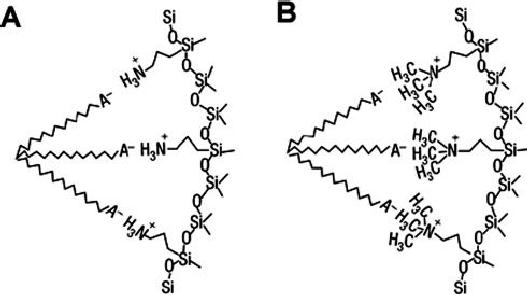
Schematic
illustration of the two
types of interactions between APS
(A) or TMAPS
(B)
and anionic surfactant headgroups.
Fig.
6.4. interactions between APS
(A) or TMAPS (B) and anionic
surfactant
headgroups
(reproduced from ref.
7)
Compared
with those cationic surfactants,
the repulsive interaction
between anionic
surfactants
and silicate species fails to
organize ordered mesostructures.
Concerning
the
charge matching effect, Che et al.
demonstrated a synthetic route to create
a
family
of mesoporous silica structures under
basic conditions by employing
anionic

6.10
Template
Based Synthesis
surfactants
as SDAs APS or TMAPS as CSDAs.
This route can be described as an
"S-
N+I-"
pathway, where N+ are cationic amino
groups of organoalkoxysilanes. Fig.
6.4
gives
the schematic illustration of
interactions between amino
groups and anionic
surfactant
head groups. The negatively
charged headgroups of the anionic
surfactants
interact
with the positively charged
ammonium sites of APS or TMAPS
electrostatic
ally
through neutralization. The
most efficient surfactant is
possibly terminal
carboxylic
acid. The co-condensation of
tetraethylorthosillane (TEOS) with APS
or
TMAPS
and assembly with surfactants
occur to form the silica
framework.
Table
6.3. Synthesis Routes to
Mesoporous Materials with
the Emphasis on Silicates
(reproduced
from ref.7)
route
interactions
symbols
conditions
classical
products
S+I-
S+,
cationic surfactants
electrostatic
basic
MCM-41,
MCM-48
I-,
anionic silicate
species
Coulomb
MCM-50,
SBA-6
force
SBA-2,
SBA-8
FDU-2,
FDU-11
FDU-
13
S-I+
S-,
anionic surfactants
electrostatic
aqueous
mesoporous
alumina
I+,
Transition metal ions
Coulomb
Force
S+X-I+
electrostatic
S+,
cationic surfactants
acidic
SBA-1,
SBA-2
I+,
cationic silicate
species
SBA-3
Coulomb
force,
double X-, Cl-,
Br-, I-,
SO4-, NO3-
layer
H bond
S-N+I-
electrostatic
S-,
anionic surfactants
basic
ASM-n
N+,
cationic amino groups
Coulomb
Synthetic
Strategies in Chemistry
6.11
I-,
anionic silicate
species
Force
S-X+I- electrostatic S-,
anionic phosphate
basic
W,
Mo oxides
Coulomb
surfactants
force,
double I-,
transition metal
ions,
layer
H bond X+,
Na+, K+,
Cr3+, Ni2+
SoIo
H
bond
So,
nonionic surfactants
neutral
HMS,
MSU,
disordered
(NoIo)
No,
organic amines
Worm-like
Io,
Silicate species,
aluminate
mesoporous
species
silicates
SoH+X-I+
electrostatic
So, nonionic
surfactants
acidic
SBA-n
(n=11,
Coulomb
12,
15, 16)
I+,
silicate species
FDU-n
(n=1, 5)
Force,
X-,
Cl-, Br-,
I-, SO42-,
NO3-1
KIT-5
and KIT-6
double,
layer
H
bond
No...I+
No,
organic amines
coordination
acidic
Nb,
Ta oxides
I+,
transition metal
bond
S+-I-
S+,
cationic surfactants
covalent
basic
mesoporous
I-,
silicate species
silica
bond
Liquid
Crystal Template
Pathway
In
this pathway true or
semi-liquid crystal mesophases
are involved in the
surfactant
assembly
to synthesize ordered mesoporous solids.
Attard and co-workers
synthesized
mesoporous silicas using high
concentrations of non-ionic surfactants
as
6.12
Template
Based Synthesis
templates.
The condensation of inorganic
precursors is improved owing to
the
confined
growth around the
surfactants and thus ceramic-like
frameworks are
formed.
After
the condensation, the
organic templates can be removed by
calciation,
extraction,
etc. The inorganic materials
"cast" the mesostuructures, pore sizes,
and
symmetries
from the liquid crystal
scaffolds. Direct templating of
microemulsion
liquid-crystal
mesophases were used to
synthesis mesoporous silicas from
butanol-
water-copolymer
silica ternary system
[6, 7].
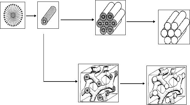
Silica/surfactant
= 1/0.27
calcination
As-synthesized
As-synthesized
MCM-41
(hexagonal
structure)
MCM-41
Silica/surfactant
=
1/0.60
calcination
MCM-48
As-synthesized
MCM-48
(cubic
structure)
Fig.
6.4. possible mechanism pathways
for the formation of M41S
family by liquid
crystal
template method (reproduced
from ref. 2).
Evaporation
Induced Self Assembling
Techniques (EISA)
Evaporation
induced self-assembly
mechanism
The
evaporation induced self
assembling technique is one of the
best techniques to
prepare
the nanomaterials. The
successful synthesis of mesoporous silica
films, the
EISA
method is engaged to prepare ordered
mesoporous polymer and carbon
materials.
The EISA method is strategy
that avoids the cooperative
assembling
Synthetic
Strategies in Chemistry
6.13
process
between the precursors and the
surfactant template. Therefore,
the cross-
linking
and thermopolymerization process of the
resols separate from the
assembly.
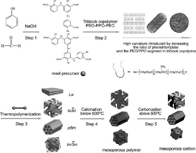
Fig.
6.5. Scheme for the
preparation of ordered mesoporous polymer resins
and
carbon
frameworks from the
surfactant templating process of
EISA. (reproduced
from
ref.
8)
Compare
to hydrothermal synthesis the
EISA method is easier and can
produce the
mesoporous
resins and carbon in a wider synthetic
range, including pH values,
surfactant
and phenol/template ratio.
The
choice of organic precursors is essential
for the EISA of the
organic organic
templating
process. The polymerization of
inorganic precursors should be low
enough
to
form a moldable inorganic-organic
framework at the initial
assembly stage of
inorganic
species with organic
surfactants. Highly ordered
mesostructures can be
formed.
The inorganic framework is
rigid. Therefore, the
mesophase can be
6.14
Template
Based Synthesis
solidified,
and the surfactant can be easily
removed by calcinations or extracted
with
ethanol.
The
synthesis procedure includes
five major steps (Fig.
6.5), which are
the
preparation
of resol precursors, the
formation of ordered hybrid mesophases
by
organic-organic
self assembly during the
solvent evaporation,
thermopolymerization
of
the resols around the
templates to solidify the ordered
mesophases, the removal
of
the
templates, and carbonization of the
resin polymer frameworks to
the homologous
carbons
[8].
Template
Synthesis of Metal
Nanostructures
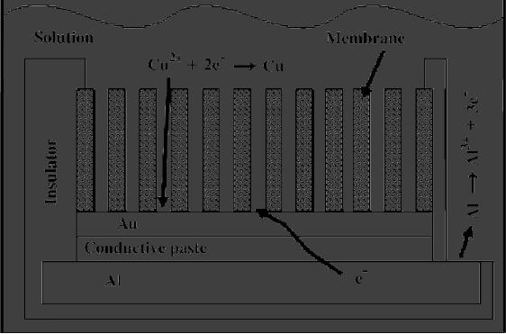
Fig.
6.6. Scheme of the
arrangement used for the
fabrication of copper nanowires
into
the AAM template (reproduced
from ref. 5)
Copper
nanowires are prepared by
using aluminium foil as
active metal having a
thickness
of 1.5 mm. In order to deposit copper
inside the channels of
anodic alumina
membrane
(AAM), prior to cementation a
thin conductive layer of Au
was sputtered
on
one side of the AAM using a
conventional sputter coater to make this
surface
electrically
conductive. A portion of AAM was mounted
onto the aluminum
support
by
means of a conductive paste and
delimited by an insulating film. Since
the
displacement
deposition process needs an
electrolytic contact of the
active metal
Synthetic
Strategies in Chemistry
6.15
surface,
a small area of the aluminum
support was exposed to the
deposition solution.
A
scheme of the arrangement
used for the fabrication of
copper nanowires is reported
in
Fig. 6.5. This arrangement
was placed horizontally in a beaker and
covered with
25
ml of a 0.2 M copper sulphate and 0.1 M
boric acid solution having pH 3.
The
experiments
were conducted at room
temperature. The surface
area of the AAM
exposed
to the deposition solution was of
the order of 1 cm2.
A fresh solution was
used
for each experiment.
Experiments were carried out
for different times
of
deposition
(from 7 h to 7 days)
[5].
Preparation
of Carbon Nanotubes
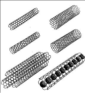
Fig.
6.7. Schematic representation of
carbon nanotubes (reproduced
from ref. 9)
Alumina
membrane is used as template
for the preparation of
carbon nanotubes; here
polyphenyl
acetylene is used as a carbon source
for the preparation of
carbon
nanotubes.
It
contains
only
carbon-hydrogen
bonds.
The
polyphenyl
acetylene/alumina
composite was prepared by adding 10 ml of
5% w/w polyphenyl
acetylene
in dichloromethane to the alumina
membrane applying vacuum from
the
bottom.
The entire polymer solution
penetrates inside the pores
of the membrane was
dried
in vacuum at 373 K for 10 min.
the composite was then
polished with fine
neutral
alumina powder to remove the
surface layers and ultrasonicated
for 20 min to
6.16
Template
Based Synthesis
remove
the residual alumina powder
used for polishing. The
composite was
carbonized
by heating in Ar atmosphere at 1173 K for
6 h at heating rate of 10 K/min.
This
resulted in the deposition of
carbon on the channel walls
of the membrane. The
carbon/alumina
composite was then placed in 48 % HF to
free the nanotubes.
The
nanotubes
were washed with distilled
water to remove HF
[9].
Preparation
of Porous Solids by Template
Method
Ordered
mesoporous carbon has been
prepared by using mesoporous silica as
the
template,
and this mesoporous silica can be
prepared by using CTAB,
P123,
surfactants
as the templates.
Mesoporous
silica SBA-15 is prepared by
the following method, P123
non-ionic
surfactant
was dissolved in 2 M HCl solution,
and it was stirred for 1 h
then TEOS
was
added as the silica source,
this mixture was stirred
until TEOS were
completely
dissolved.
The mixture was placed in oven at 373 K
for 48 h. The product was
filtered
and
washed with distilled water and
dried at 333 K for 6 h and then
SBA-15 was
calcined
at 823 K for 6 h in air
atmosphere.
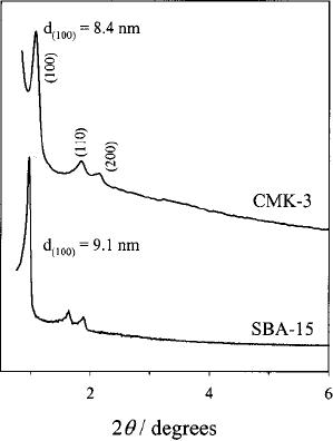
Fig.
6.8. XRD patterns of SBA-15
and CMK-3 (reproduced from
ref. 10)
Synthetic
Strategies in Chemistry
6.17
The
calcined SBA-15 was impregnated
with aqueous solution
sucrose containing
sulfuric
acid, this mixture was
heated to 373 k to 433 K for 24 h. then
the
carbonization
was completed by pyrolysis with
heating to typically 1173 K
under N2
atmosphere
for 6 h at the rate of 5 K/min.
the carbon-silica composite
obtained was
washed
with 1 M NaOH solution or 5 Wt %
hydrofluoric acid at room temperature,
to
remove
the silica template. The
template free carbon product
thus obtained was
filtered,
washed with ethanol and dried at 393
K.
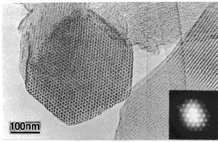
In
Fig. 6.9 the low
angle XRD conforms the
mesoporous structure and to support
this
mesoporous
structure the transition
electron microscopy images
shows the presence
of
ordered mesoporous structure [10].
Fig.
6.9 TEM and selected area
electron diffraction (SAED)
images of CMK-3
(reproduced
from ref.10)
SUMMARY
Strategy
aimed at the controllable synthesis
has been focused on the
control of micro,
meso
and macroscale, including synthetic
methods, architecture concepts,
and
fundamental
principles that govern the
rational design and synthesis. In this
chapter,
synthesis
mechanisms and the corresponding
pathways are first
demonstrated for the
synthesis
of mesoporous silicates from the
surfactant-templating approach.
Virtually
all
mesoporous silicates begin with an
understanding of the interaction
between
organic
surfactants and inorganic species, as
well as among
themselves.
6.18
Template
Based Synthesis
Soft
templating approach is one of the most
general strategies now
available for
crating
nanostructures. The assembly of
surfactants and silicates species is
normally
carried
in solutions or the interface to
allow the required driving
force for the
formation
of nanostructures. Relying on sol-gel,
solution and surface chemistry,
there
is
great potential to explore novel
strategies for mesostructures,
especially a strategy
that
can utilize interfacial tension.
Items that attract attention
also include the
control
of
weak interaction such as the
hydrophobic interaction between
the assembling
components.
In view of the fact that
surfactant self-assembly can occur
with
components
larger than 1 nm continuous to be
challenge and an interest in
condensed
matter
science.
REFERENCES
1.
J. Lee, J. Kim, T. Hyeon, Adv.
Mater.,
18 (2006) 2073.
2.
C. T. Kresge, M. E. Leonowicz, W. J. Roth, J. C.
Vartuli, J. S. Beck,
Nature,
359 (1992)
710.
3.
D. Zhao, J. Feng, Q. Huo, N. Elosh, G. H.
Fredirckson, B. F. Chemlka,
G.
D. Stucky, Science, 279
(1998)
548.
4.
G. Cao, D. Liu, Adv.
Colloid. Interface. Sci. 136
(2008) 45
5.
R. Inguanta, S. Piazza, C. Sunseri, Eleectrochem.
Commun., 10
(2008) 506
6.
A. Corma, Chem.
Rev. 97 (1997)
2373.
7.
Y. Wan, D. Zhao, Chem.
Rev. 107
(2007) 2821.
8.
Y. Meng, D. Gu, F. Zhang, Y.
Shi, L. Cheng, D. Feng, Z. Wu, Z.
Chen,
Y.
Wan, A. Stein, D. Zhao, Chem.
Mater.,
18 (2006) 4447.
9.
M. Sankaran, Ph.D Thesis,
Indian Institute of Technoloyg
Madras, 2007.
10.
S. Jun, S. Joo, R. Ryoo, M.
Kruk, M. Jaroniec, Z. Liu, T.
Ohsuna,
O.
Terasaki, J.
Am.Chem. Soc.,
122
(2000) 712.
Chapter
- 7
MICROEMULSION
TECHNIQUES
Ch.
Venkateswara Rao
The
main focus of this chapter
is to give brief introduction to
the microemulsion systems,
formation
of microemulsions, how those
microemulsions can be used for
the preparation of
various
types of nanoparticles and the
dominant factors that
influence the
nanoparticles
preparation
in the microemulsion.
INTRODUCTION
In
1943, Hoar and Schulman
first reported that oil can
be dissolved in bulk water or
water in
bulk
oil with the aid of
surfactant to produce a clear homogeneous
solution. The oil phases
are
simple
long-chain hydrocarbons and the
surfactants are long-chain
organic molecules with
a
hydrophilic
head (usually an ionic
sulfate or quarternary amine) and
lipophilic tail. The
generally
used
oil phases are cyclohexane,
decane, heptane and surfactants are
cetyltrimethylammonium
bromide
(CTAB), sodium bis(2-ethylhexyl)
sulfosuccinate (AOT).
The
clear homogeneous
solution
is called as microemulsion. According to
the nature of the bulk
solvent used in the
microemulsion,
they are designated as
water-in-oil or oil-in-water
microemulsions. The
microemulsion
is primarily distinguished from
the emulsion not by being
composed of smaller
droplets
but by being subjected to a
restrictive condition that it is
thermodynamically stable.
MICROEMULSION
FORMATION AND NANOPARTICLES PREPARATION
In
general, water and oil are
not miscible. But the
amphiphilic nature of the
surfactants such as
CTAB
makes them miscible. The
surfactant molecules form a
monolayer at the
interface
between
the oil and water, with
the hydrophobic tails of the
surfactant molecules dissolved in
the
oil
phase and the hydrophilic
head groups in the aqueous
phase. It leads to the
formation of
microemulsion.
So the microemulsion is defined as a
system of water, oil and
surfactant. This
system
is an optically isotropic and
thermodynamically stable. At macroscopic
scale, a
microemulsion
looks like a homogeneous
solution but at molecular
scale, it appears to be
heterogeneous.
Even though it is optically
isotropic; it cannot be properly
described as a solution.
The
internal structure of the
microemulsion at a given temperature is
determined by the ratio
of
its
constituents. The structure consists
either of nanospherical monosized
droplets or a
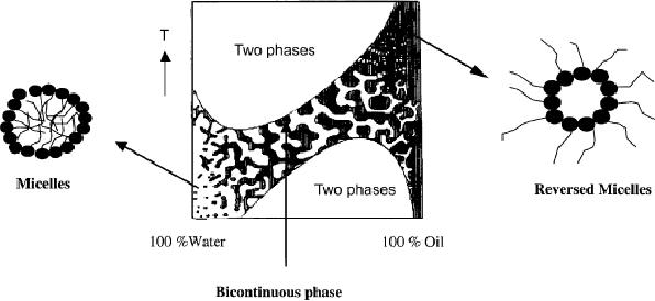
7.2
Microemulsion
Techniques
bicontinuous
phase. The different
structures of a microemulsion at a given
concentration of
surfactant
are shown in Fig 1. It
indicates that
(i)
At
high concentration of water,
the internal structure of
the microemulsion consists of
small
oil droplets in a continuous
water phase (micelles),
known as o/w
microemulsion.
(ii)
With
increased oil concentration, a
bicontinuous phase without
any defined shape is
formed.
(iii)
At
high oil concentration, the
bicontinuous phase is transformed
into a structure of
small
water droplets in a continuous
oil phase (reverse
micelles), known as a
w/o
microemulsion.
Depending
on the type of surfactant
used to form microemulsion, size of
the different
droplets
will be varied from 5-100
nm. It is also evident that
the microemulsion system
is
sensitive
to temperature. It can be seen in Fig.
7.1 that the increase in
temperature will
destroy
the oil droplets while
the decrease in temperature will
destroy the water
droplets.
Fig.
7.1 The microscopic
structure of a microemulsion at a given
concentration of surfactant as
function
of temperature and water concentration
(reproduced from ref.
20).
Significance
of Packing Parameter
The
shape of micellar aggregates and
the formation of microemulsion can be
understood from
the
packing parameter of surfactant molecule
used for the microemulsion
formation. Packing
The
Evolving Synthetic Strategies in
Chemistry
7.3
parameter
is defined as v/a.l, where
v
is
the volume of hydrocarbon of
the surfactant, a
is
the
polar
head area and l
is
the fully extended chain
length of the surfactant.
The packing parameter
value
can be 1, <1 and >1. When the
packing parameter value (or
ratio v/a.l) is greater
than 1, the
aggregate
curvature will be toward the
water. This corresponds to a situation
where the oil is
penetrating
the surfactant tails and/or
the electrostatic repulsion
between the charged head
group
is
low. When the packing
parameter value (or ratio v/a.l)
is less than 1, it corresponds to
a
situation
where the electrostatic
repulsion is larger and/or
the oil is not penetrating
the surfactant
tails.
It implies that (i) when
oil is solubilized in hydrophilic
micelles, one can observe the
formation
of o/w microemulsions for v/a.l<1; (ii)
when water is solubilized in
hydrophobic
micelles,
one can observe the formation of w/o
microemulsions for v/a.l>1.; and
(iii) When
v/a.l≈1,
lamellar phases or bicontinuous
microemulsions are observed.
Based
on the experimental results, it is
observed that the micelles will be in
spherical shape
when
the packing parameter is less
than 1/3. The packing
parameters for cylinders and
planar
bilayers
are 0.5 and 1, respectively. In
the case of reverse micellar
structures, the
packing
parameter
is greater than 2 for cylinders as
well as spherical micelles. It was
observed that
reverse
micelles will be in cylinder shape up to
v/a.l≤2
and spherical shape when v/a.l>3.
Oil-in-water
(o/w) microemulsions are monodisperse.
Water-in-oil (w/o)
microemulsion
solutions
are mostly transparent,
isotropic liquid media with
nanosized water droplets
that are
dispersed
in the continuous oil phase
and stabilized by surfactant molecules at
the water/oil
interface.
These surfactant-covered water pools
offer a unique microenvironment
for the
formation
of nanoparticles. They not
only act as micro-/nano-reactors for
processing reactions
but
also exhibit the process aggregation of
particles because the
surfactants could adsorb on
the
particle
surface when the particle
size approaches to that of the
water pool. As a result,
the
particles
obtained in such a medium
are generally uniform in size and
shape (i.e.,
monodisperse).
APPLICATIONS
OF MICROEMULSIONS
1.
Synthesis of Metal
Nanoparticles
Precipitation
of metal particles in the
Water-in-oil (w/o) microemulsion
solutions (reverse
micellar
system) has been found to be
the simple methodology for
the preparation of
nanoparticles.
7.4
Microemulsion
Techniques
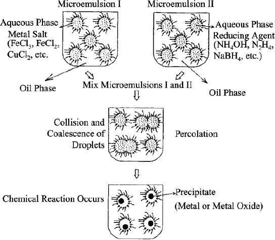
The
method of nanoparticle preparation
consists in mixing of two microemulsions
carrying the
appropriate
reactants (generally metal precursor and
reducing agent) in order to
obtain the
desired
particles. It is represented in Scheme
7.1.
Scheme
7.1. Proposed mechanism for
the formation of metal
particles by the
microemulsion
approach
(reproduced from ref.
24)
At
the beginning of reaction,
the attractive van der Waals
force and the repulsive
osmotic force
between
reverse micelles lead to collisions of
micelles. It results in the
interchange of the
reactants
(in general, metal ions and
reducing species) solubilized in
two different reverse
micelles
respectively. As a result, the
initial monomeric metal
nuclei begin to form and
grow.
When
the exchange of reactants is fast in
the water droplets, metal
ions reduce and the
metal
nuclei
grow quickly. It remains
unchanged when the particle
size reaches a certain size.
It
corresponds
to the thermodynamically stabilized
species in the presence of
microemulsion. Due
The
Evolving Synthetic Strategies in
Chemistry
7.5
to
the possible aggregation, the
final size of silver particles is
generally larger than that
of the
water
cores. Once the particles
attain the final size,
the surfactant molecules are
attached to the
surface
of particles and stabilize and protect
them against further growth.
The dynamic exchange
of
reactants such as metallic salts and
reducing agents between
droplets via the continuous
oil
phase
is strongly depressed due to the
restricted solubility of metal salts in
the oil phase. This is
a
reason
why the attractive interactions
(percolation) between droplets
play a dominant role in
the
particle
nucleation and growth in the
water-in-oil (w/o) microemulsion
reaction medium.
2.
Synthesis of Metal
Alloys
Various
metal alloys can be prepared in
the similar way as described
in scheme 1. It consists of
mixing
the reverse micelle containing
two or three metal precursors and
another reverse micelle
contain
reducing species. Example:
formation of Pt-Ru (1:1)
alloy. In order to prepare
the alloy
nanoparticles,
both Pt4+ and Ru3+
will be taken
in 1:1 atomic ratio to form
reverse microemulsion
I.
Reverse microemulsion II will be prepared by
using NaBH4 reducing agent. When both
the
reverse
microemulsions are mixed
together, reduction of Pt4+ and Ru3+
takes place by
BH4- ions
and
results in the formation of
Pt-Ru (1:1) nanoparticles
(Xiong and Manthiram, 2005). In
the
similar
way, Pt-Fe nanoparticles in different
ratios (1:1, 1:2 and 1:3)
can be prepared (Carpenter
et
al.,
2000). In the same manner,
various metal chalcogenides also can be
prepared by taking
two
micelle solutions containing
the desired ions prepared
separately and then rapidly
mixed.
In
conventional methods of preparation,
the reaction temperature
should be high to
promote
alloy
formation. As a result, the
formed particles will be large in
size. Moreover, the shape of
the
particle
cannot be controlled. Since the
reaction takes place inside
the micellar cores,
(i)
the enormous amount of heat
that is generated within the
micellar cores during the
reduction
process
is enough to form alloy of
desired composition.
and
(ii) both size, shape and
composition can be controlled.
3.
Synthesis of Metal
Oxides
The
synthesis of oxides from reverse
microemulsion relies on the
co-precipitation of one or more
metal
ions. It is almost similar in
many respects to the
precipitation of oxides from
aqueous
solutions.
But the precipitation occurs
within the micellar cores so
that particle size as well
as
shape
can be controlled. In a typical process,
precipitation of hydroxides is induced by
addition
of
a reverse micelle solution containing
dilute NH4OH
to a reverse micelle solution
containing
aqueous
metal ions at the micellar
cores. Alternatively, dilute
NH4OH can
simply be added

7.6
Microemulsion
Techniques
directly
to a micelle solution of the
metal ions. The
precipitation of the metal
hydroxides is
typically
followed by centrifugation and heating in
the presence of oxygen to
remove water
and/or
improve crystallinity. In general, it is
represented as follows:
A2+ +
2B2+ + OH-
(excess) → AB2O4 + xH2O↑
Where
A and B are metals.
In
this way, simple metal
oxides and multicomponent metal
oxides can be prepared. Some of
the
examples
of nanomaterials synthesized in w/o
microemulsions are given in
Table 7.1.
Table
7.1. Nanomaterials formed in
w/o microemulsions
Nanoparticle
system
Example
Reference
Pt
Metals/Metal
alloys
Rojas
et
al.,
2005
Pd
Boutonnet
et
al.,
1982
Ag
Taleb
et
al.,
1997
Au
Herrera
et
al.,
2005
Pt-Ru
Xiong
and Manthiram, 2005
Fe-Pt
Carpenter
et
al.,
2002
Pd-Co-Au
Raghuveer
et
al.,
2006
ZnS
Metal
chalcogenides
Khiew
et
al.,
2005
PbS
Eastoe
et
al.,
1995
RuSe
Venkateswara
Rao and Viswanathan, 2007
Pb2Ru2O7
Metal
oxides
Raghuveer
et
al.,
2002
CeO2
Bumajdad
et
al.,
2004
CoFe2O4
Liu
et
al.,
2003
LiNi0.8Co0.2O2
Lu
et
al.,
2000
Core-shell
nanoparticles
Fe3O4/SiO2
Tago
et
al.,
2002
Fe/Au
Zhou
et
al.,
2000
The
Evolving Synthetic Strategies in
Chemistry
7.7
4.
Synthesis of Core-Shell
Nanoparticles
Some
of the metallic nanoparticles
like Fe, Co, Ni are
susceptible to rapid oxidation.
This
problem
can be largely circumvented by coating
the nanoparticles with gold
or other inert
metals.
The technique for applying
gold coatings on metal
nanoparticles is reasonably
straightforward
and simply adds an additional
step to the reverse micelle
synthesis. In this
process,
a water-soluble gold salt
(HAuCl4)
is dissolved and dispersed in a separate
reverse
micelle
solution that is then added
to the metal-containing reverse micelle
solution that has
already
been reduced with an excess of
BH4-.
The aqueous AuCl4- ions encapsulate the
metal
particles
and are subsequently reduced by forming a
metallic gold shell around
the metal
particles.
8AuCl4- + 3
BH4- + 9H2O →
8Au + 3B(OH)3
+
21H+
+
32Cl-
The
preparation of core-shell type
structures is not limited to
metals as the core or
shell
materials.
Combinations of precipitation, reduction
and hydrolysis reactions can be
performed
sequentially
to produce oxides coated
with metals, oxides coated
with oxides, and so
forth.
EFFECTS
OF THE PARAMETERS ON THE FORMATION OF NANOPARTICLES
IN
MICROEMULSION
The
main parameters that
influence the size of
nanoparticle are molar
ratio, W =
[water]/[surfactant],
type of solvent employed,
surfactant or co-surfactants used
and
concentration
of reagents. Recent investigations
suggest that the particle
shape also can be
affected
by the influence of micellar
template, added anions and
molecular adsorption. But
a
general
method for controlling
nanocrystal shapes through
soft chemistry has not
yet been found.
The
major factors that influence
the formation of nanoparticles
are explained with
examples
below.
Water-to-Surfactant
Ratio, W
The
size of the metallic particle will
depend on the size of the
droplets in the microemulsion.
The
droplet
size will be influenced by the
water-to-surfactant ratio, W.
In
general, the volume of water
in microemulsions is proportional to the
cubic radius of the
water
core. And also the amount of
surfactant which is present as a film
around the water cores
is
proportional
to the surface area of the
micro/nanodroplets. So the molar
ratio of water to
surfactant
(W) has a linear
relationship with the radii
of the water cores (Rw). It
has been
observed
in AOT microemulsion system that
the water-pool radius
increases with the
water

7.8
Microemulsion
Techniques
content.
An increase of molar ratio, W at
constant concentration of surfactant will
increase the
average
diameter of the droplets.
Consequently, the obtained
nanoparticles will be large in
size.
Table
7.2. Characteristic of silver
particles obtained in w/o
microemulsion (data taken from
ref.
23)
W
Reducing
agent
Conc.
of reducing
Particle
size (nm)
agent
(M)
2.5
x 10-4
-
NaBH4
2
2.5
x 10-4
2.7
NaBH4
5
1.0
x 10-5
-
NaBH4
7.5
1.0
x 10-4
4.5
7.5
NaBH4
2.5
x 10-4
5.5
NaBH4
7.5
1.0
x 10-4
6.0
NaBH4
15
2.5
x 10-4
7.0
NaBH4
15
For
example, by dynamic light
scattering technique, it has
been confirmed that the
water core
radius,
Rw, is
coincident with the equation
Rw(nm) = 0.18W + 1.5 in a
wide range of alkanes. For
example
in the AOT-water-isooctane microemulsion
system, it was found that
the linear
relationship
between Rw and W was Rw
(Å) =
1.5W. Thus the linear
relationship may be
different
in
various systems. Generally, low
water content is favorable to
form smaller
microemulsion
droplets
(reverse micelles) which
yield fine nanoparticles
with a narrow size distribution. On
the
contrary,
high water content is
favorable to form bigger
microemulsion droplets which
are easy
to
fabricate larger particles.
The reason for the
behaviour is explained as follows:
Actually, at
low
water content, the water
solubilized in the polar core is
bound by the surfactant
molecules,
which
increases the boundary
strength and decreases the
intermicellar exchange rate. As a
result,
a
decrease in water content
induces formation of monodisperse
nanoparticles with small
particle
size.
However, the bound water
would turn into bulk
water with an increase in
water content,
which
is benefit for the water
pools to exchange their
contents by collisions and makes
the
chemical
reaction or co-precipitation between
compounds solubilized in two
different reverse
micelles
complete more quickly. Since
the nature of bulk water is
drastically different from
that
of
bound water, reactants would be
rapidly transferred from one
water core to another, and
thus

The
Evolving Synthetic Strategies in
Chemistry
7.9
the
resultant particle size is relatively
big and the size distribution
becomes relatively wide.
The
variation
of silver and Fe nanoparticles size with
W is given in Tables 7.2 and
7.3 respectively.
Table
7.3. Characteristic of iron
particles obtained in w/o
microemulsion (Data taken
from ref.
24)
[FeCl2]x104
[NaBH4]x103
Particle
size
S.
No
[AOT]
W
(mol/dm3)
(mol/dm3)
(nm)
3.9
3.5
7.5
22
0.1
1
4.1
0.68
1.6
22
0.1
2
2.5
0.35
0.93
10
0.05
3
1.9
24
48
5
0.025
4
2.5
24
48
9
0.025
5
3.3
24
48
13
0.025
6
4.3
24
48
18
0.025
7
4.7
24
48
22
0.025
8
5.4
24
48
26
0.025
9
5.8
24
48
31
0.025
10
Solvent
Effect
Particle
size is affected by solvent type.
This was shown initially by
Pileni (2003) in a study
on
silver
nanoparticles, in which larger
particles were seen (by
TEM) to be formed in isooctane
than
in
cyclohexane. This is probably due to
the significant difference in
intermicellar exchange rate
constant
between the two solvents - a
factor of 10.
The
change in growth rate has been
explained in the following
way:
(i)
Smaller
and less bulky solvent
molecules with lower
molecular volumes such
as
cyclohexane,
can penetrate between surfactant tails
and increase the
surfactant
curvature
and rigidity. The increased
rigidity at the interface
may lead to a slower
growth
rate.
Table of Contents:
- INTRODUCTION TO SYNTHETIC STRATEGIES IN CHEMISTRY:POROUS MATERIALS
- SYNTHETIC METHODS BASED ON ACTIVATING THE REACTANT:HALOGENATION OF BENZENE
- METHODS BASED ON ACTIVATING THE REACTING SUBSTANCE:Experimental method
- SYNTHESIS OF MATERIALS BASED ON SOLUBILITY PRINCIPLE
- SOL-GEL TECHNIQUES:DEFINITIONS, GENERAL MECHANISM, INORGANIC ROUTE
- TEMPLATE BASED SYNTHESISSynthesis, Mechanism and Pathway
- MICROEMULSION TECHNIQUES:Significance of Packing Parameter
- SYNTHESIS BY SOLID STATE DECOMPOSITION:DECOMPOSITION METHODS
- NEWER SYNTHETIC STRATERGIES FOR NANOMATERIALS:Nanostructured Materials
- THE ROLE OF SYNTHESIS IN MATERIALS TECHNOLOGY:The Holy Bible
- ELECTROCHEMICAL SYNTHESIS:FEATURES OF ELECTROCHEMICAL SYNTHESIS
- NEWER REACTIONS AND PROCEDURES: CATALYTIC AND NONCATALYTIC
- SYNTHETIC STRATEGIES - FROM LABORATORY TO INDUSTRY
- SYNTHESIS OF CHEMICALS FROM CARBON DIOXIDE:Carbon dioxide - Dry Ice
- CARBOHYDRATES TO CHEMICALS:MONOSACCHARIDES
- SOME CONCEPTUAL DEVELOPMENTS IN SYNTHESIS IN CHEMISTRY
- COMPUTATIONAL BASICS UNDERLYING SYNTHETIC STRATEGIES