 |
[IP
Telephony Cookbook] /
Setting Up Basic
Services
Setting
Up Basic Services ~
4
In
Chapter 2, the working of
H.323 and SIP protocols
was explained.This chapter explains
how
to
set up an infrastructure including
H.323 and/or SIP components
and gives real-world
examples
of configuration for popular equipment.The
focus will be on setting up
basic services,
meaning
the equipment that is necessary to
provide basic call services,
authentication and
billing.
~
4.1
General concepts
Before
giving examples on how to
set up SIP or H.323 zones
using equipment from
specific
vendors,
this section introduces the
general concepts.With these concepts in
mind, it will be
easier
to understand the vendor-specific
parts that follow.
~
4.1.1
Architecture
Chapter
2 introduced us to the architectures of
pure H.323 and SIP
environments. Basically,
there
is
one central server and
multiple telephony endpoints
registering with that
server.The server's
task,
among others, is to resolve a
dialled address to an IP target.
However, when we talk
about
real-world
set-ups, this server
infrastructure tends to be more
complicated.The reasons for this
are:
-
usage of redundant servers to
increase availability or provide load
balancing (see Section
4.1.2);
-
usage of multiple servers,
e.g., for branch
offices;
-
more than one signalling
protocol.
There
are two possibilities to
support multiple signalling
protocols within one zone:
have servers
with
built-in support for every
protocol or have dedicated servers
for each protocol and
signalling
gateways
between them.
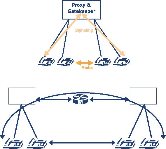
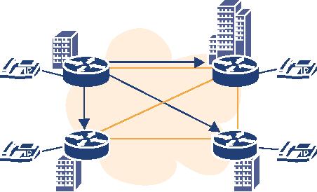
A
server that supports more
than one signalling protocol
(see Figure 4.1) is the
best solution. It is
easier
to manage since there is
just one configuration to take
care of and there will
not be any
problems
with server-to-server interaction.
Unfortunately,
there seems to be no equipment that
provides fully-featured SIP and
H.323
support
on the same machine.1
If
a zone includes both a SIP
Proxy as well as an H.323
Gatekeeper, then call
routing inside the
domain
becomes an issue. A signalling
gateway is required to enable an
H.323 endpoint to call a
SIP
endpoint and vice versa (see
Figure 4.2).
1.
Actually
there is a product that
claims support for both
SIP and H.323 protocols:
the Asterisk PBX.
See:
http://www.asterisk.org/. How well it
supports SIP and H.323 is
not yet known.
P.64
[IP
Telephony Cookbook] /
Setting Up Basic
Services
Figure
4.1 SIP/H.323 zone using a
multi-protocol server
Signalling
H.323
SIP-Proxy
Gatekeeper
Registration
Registration
Media
Figure
4.2 SIP/H.323 zone using a
signalling gateway
The
gateway is used to translate
signalling between the two
worlds.The media stream may
still be
exchanged
directly between the endpoints, but
eventually (see Section
5.1.4.4) the gateway
needs
to
transcode different codecs, even if both
endpoints support the same
codec.This problem might
occur
if either the gateway or the
entity calling the gateway (endpoint or
gatekeeper) does not
support
FastConnect (see Section
2.2.1.5.1).
An
architectural problem similar to the last
one is the use of servers
that feature a proprietary IP
Telephony
protocol and provide a SIP or an
H.323 interface that is
limited to basic call
functionality
without any supplementary
services or security features. An
example of this is
the
popular
Cisco CallManager.
~
4.1.1.1
PSTN gateways / PBX migration
The
most common scenario for
introducing IP Telephony systems is to
integrate them with
an
existing
PBX. On the technical side,
this usually involves a
gateway that translates
between H.323
or
SIP and QSIG or other
protocols over an S2M
interface.The services that
can be provided
between
the legacy PBX and
the IP world will depend on
the QSIG implementation of
the PBX
and
the gateway vendor.There is no
general advice here but to
test before buying.
P.65
[IP
Telephony Cookbook] /
Setting Up Basic
Services
Besides
technical aspects, organisational
aspects of PBX-VoIP integration call
for careful planning
and
analysis.The question is how to
integrate legacy and IP
Telephony equipment into the
dial
plan
of an organisation. Is it necessary that
the phone number reflects
whether the participant is a
VoIP
user or a PBX user.
Generally,
there are three
possibilities to explore, as explained
below.There are more details on
setting
up an IP Telephony gateway in Section
5.1.
4.1.1.1.1.
Routing based on a number
prefix
This
option requires that, in the
dial plan, there is a numberblock
available for IP Telephony
use.
This
is easy to implement on legacy
PBXs and IP Telephony
servers but the result is
new phone
numbers
for every user that
switches from legacy to IP
Telephony.
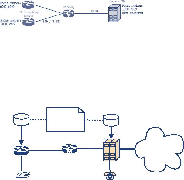
Figure
4.3 Routing based on number
prefix
In
this example, the PBX is
configured to forward every call
starting with the prefix 8
or 9 to the
gateway.The
gateway passes the call to
one of the IP Telephony
servers depending on the
prefix 8
or
9. Unknown target prefixes
are routed to the legacy
PBX. An IP Telephony server
only needs
to
route all internal calls
with unknown prefixes to the
gateway.
4.1.1.1.2.
Per-number routing, one
server: per-number routing on
the PBX.
When
migrating from a legacy PBX
towards IP Telephony, provision of
seamless migration is
often
required for users switching
over from the PBX to
the IP world, e.g., when a
user decides to
switch
to IP Telephony but wants to keep
his telephone number.
Database
Database
2972
-> PSTN
2973
-> IP
2974
-> IP
2975
-> PSTN
Legacy
PBX
Gateway
IP
telephony
PSTN
server
2973
2972
Figure
4.4 Per-number
routing
P.66
[IP
Telephony Cookbook] /
Setting Up Basic
Services
This
is quite easy to achieve by setting up a
database that stores the
information for
telephone
numbers
that belong to the PBX or
the IP world (see Figure
4.4).The IP Telephony server
and
the
PBX access the same
data to decide where to route a
call. Calls to external targets
are routed
to
the PBX and out
into the PSTN.
There
are variations to this
scenario. Indeed, it is quite unusual
that an IP Telephony server
uses
the
same database as the PBX,
unless they are from
the same manufacturer.Then
there are two
possibilities:
setting up a second database
suitable for the IP
Telephony server (and
risk
inconsistencies)
or let the IP Telephony server
route calls to unregistered
targets to the
PBX.The
latter
is easier to implement but prevents
the discarding of the PBX
and the use of IP
Telephony
providers
in the future.
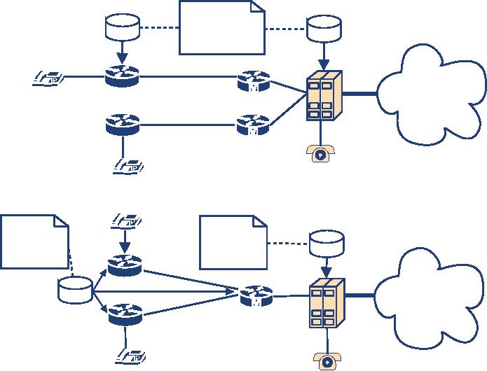
4.1.1.1.3.
Per-number routing: more
than one server
A
similar but more complex scheme is the
variant where there is more than
one IP Telephony
server
in the IP world, e.g., a
server for each signalling
protocol used. In this case,
there needs to
be
a database that contains not
only the information about
which number shall be reached on
the
PBX
and which in the IP world,
but also the information
about which IP server (and
signalling
protocol)
to use.
Database
(a)
Database
2972
-> PSTN
2973
-> IP A
2974
-> IP B
2975
-> PSTN
2974
Legacy
PBX
B
IP
telephony
PSTN
Gateway
server
A
2972
2973
(b)
Database
2974
2972
-> PSTN
2972
-> PSTN
2973
-> IP A
2973
-> IP A
2974
-> IP B
2974
-> IP B
2975
-> PSTN
2975
-> PSTN
Legacy
PBX
B
IP
telephony
server
PSTN
Database
Gateway
2973
2972
Figure
4.5 Per-number routing with
a) two gateways or b) one
gateway
P.67

[IP
Telephony Cookbook] /
Setting Up Basic
Services
The
first scenario uses two
gateways and thus allows
the PBX to decide where to
route a call to.
IP
Telephony servers route
calls they cannot resolve
locally through a dedicated gateway to
the
PBX
and let it make the routing
decision. If both IP Telephony servers
support the same
signalling
protocol, they may contact
each other directly (see
Section 4.1.1.2).
The
second scenario uses only
one gateway, so the PBX
does not need to know
which IP
Telephony
server to contact, but merely
needs to know the fact
that the call has an IP
target.
Components
in the IP world share a
common configuration database that
locates a specific
number
on server A (e.g., a SIP Proxy) or B
(e.g., an H.323 gatekeeper).This
allows any server or
gateway
component to make routing
decisions.
The
described scenario may vary
in many ways.The assumption
that all IP components use
the
same
routing database is often
difficult to achieve, especially if
products from different
manufacturers
are used, because there is
no common format for such
entries. In this case, it
might
well
be that a separate database is
maintained for each component,
leading to administrative
overhead
for their synchronisation
with a high risk of inconsistency.
~
4.1.1.2
Trunking
The
bigger an institution is,
the more complex its
organisational infrastructure.This may be
due
to
the need to support multiple
locations (sites) or because
certain organisational units
need to
administer
their own communication
solutions (and eventually do
not adhere the
institution's
standard
procedures). Either way, the
IP Telephony system probably
consists of more than
one
server,
all with the need to
share the same dialling
space.
4.1.1.2.1
Prefix-based trunking
One
possibility of connecting two or more networks is to
give each network a different
prefix
and
make routing decisions based
upon those prefixes.This works
best if the current PSTN
dial
plan
already provides these
prefixes, e.g., in the form
of area codes plus
subscriber prefixes.
PSTN
1000-4999
5000-6999
8000-9999
7000-7999
IP
Figure
4.6 Prefix-based
trunking
P.68
[IP
Telephony Cookbook] /
Setting Up Basic
Services
This
is the classic branch office
scenario that is based upon
the assumption that both
networks
have
different locations, and that
dialling prefixes already
exist in the PSTN.This is
the same
problem
as the one already addressed
in Section 4.1.1.1.1.
4.1.1.2.2
Static individual
routing
Prefix-based
routing fails to work if you
have more than one IP
Telephony server and a PBX,
all
of
them within the same
dialling address space, and
want to allow users to
change their legacy
PBX
phone for an IP phone
without switching to a new
phone number.
An
example of such a scenario is a
university that has no structure in its
PBX dial plan and
that
now
introduces IP Telephony, but has a computer
science faculty that runs
its own IP Telephony
server.
How does the system know
where to route a dialled
number?
Obviously,
a central database storing routing
information for each phone
number would be a
good
idea (see Figure 4.7).This
usually works, only if all
routing entities support the
same kind of
database,
meaning that the legacy
PBX and the new IP
Telephony server must share
the same
database.
Such a solution is most probably
only possible if the PBX
and the IP Telephony
server
come
from the same
vendor.
2972
-> A
2973
-> B
2974
-> C
2975
-> D
D
A
2975
2972
2974
2973
IP
C
B
Figure
4.7 Static individual
trunking
A
more likely solution is a model where a PBX `knows'
which numbers are located in
the IP
world
and the IP Telephony servers
use a shared database that
defines which number belongs
to
which
server. If there are different
types of IP Telephony servers, it
may be that they are
unable to
share
a common routing database in
which case each server has
its own database, resulting
in
administration
overhead and risk of
inconsistency.
P.69
[IP
Telephony Cookbook] /
Setting Up Basic
Services
4.1.1.2.3
Dynamic individual
routing
The
previously introduced possibilities
required some kind of static
configuration to bind a
number
to a specific server.These scenarios
usually end up using at
least one routing database,
but
often
more.The requirement for such a
burden presumably has its
roots in the classic
PBX
mentality
of static configuration. In the IP world,
the network offers the
possibility of carrying
information
from one server to another
so that IP Telephony protocols
provide the means to
dynamically
exchange routing information.The
mechanisms can generally be divided
into `Push'
and
`Pull' techniques.When using a
`Push' mechanism, a server
informs its peers of every
endpoint
that
registers or un-registers from
the server, thus allowing
its peer servers to
immediately make
routing
decisions if necessary. On the
other hand, care must be
taken that servers that
are
integrated
later, be synchronised.
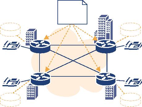
`Pull'
mechanisms are used when a
server asks its peer
servers for a target address
when it needs to
resolve
an external target address.The peer
giving a positive reply
receives the routed call
(see
Figure
4.8).
In
H.323, trunking is achieved by LRQ
messages (see Section
7.1.1). SIP has no extra
mechanism
for
address resolution but is able to
fan out a call to multiple
servers at the same time.
Both
signalling
protocols may use TRIP
(see Section 7.1.3) to distribute
numeric addresses, but
not
names.
D
A
2975
2972
2974
2973
IP
C
B
Figure
4.8 Dynamic individual
trunking
~
4.1.2.
Robustness
A
highly-available telephony infrastructure
must deal with the
fact that an IP Telephony
server
might
crash or be down for
administrative reasons.Telephony services
can be affected adversely
in
various
ways, when a server goes
down and another server
takes over.The following are
some
approaches
for implementing robustness in
the server
infrastructure.
P.70
[IP
Telephony Cookbook] /
Setting Up Basic
Services
1.The first
approach is to set up more than
one server for a zone
and treat each of them as
a
separate
router (see Section
4.1.1.2.3) that shares the
same configuration. In this case,
there is no
replication
of registration or call data
across multiple
servers.
If
the primary server fails, a
calling phone will not even
notice, at first, because the UDP
media
stream
is usually transmitted directly between
the two endpoints. But,
the TCP signalling
connections
do not survive such a crash
and so the first TCP message
sent afterwards leads to
an
error
and, very likely, to a call
clearing.
A
phone that is not currently in a
call has no way of detecting a
server crash in time. After
its
registration
period expires, it will try to
refresh its registration
with the primary server
and fail.
It
then needs to find a new IP
Telephony server. H.323
provides a mechanism called
`Alternate
gatekeeper'
which basically defines that
a gatekeeper registering an endpoint
informs it of
possible
secondary gatekeepers that
can be used alternatively.The
telephone stores this
information
and, in case of a server
failure, tries to contact
the other listed
gatekeepers.
Another
possibility that works for SIP
and H.323 is to configure a
prioritised list of H.323
Gatekeepers
or SIP proxies in a DNS SRV
record for the zone.This
requires that the
telephone
is
aware of its DNS domain and
is able to query DNS
servers, a concept that is
common in the
SIP
world, but seldom found in H.323
devices.
In
general, without synchronisation
between the replicated
servers the failure of one
server
normally
results in the loss of all
calls.The server loss is
discovered after the defined
registration
timeout,
which usually is measured in
minutes - but theoretically can also be
set to days. After
that
time, the phones should be
able to find an alternate IP
Telephony server to register
with.
2.
Another
approach is to use servers
that maintain replicated registration
data while only one
of
them
is the active server and
the other is the standby
server. If the active server
fails, the standby
server
detects this instantly and
can use the replicated
information about which
devices are
registered
to inform all endpoints
(phones) that it is now the
new active server. As a
result, the
outage
will be noticeable for only
a few seconds. Of course,
active calls will still be
cleared, and
definitely
not resumed.
3.
If the
previous approach is pushed a
bit further, both servers could
replicate every kind of
state
they
keep internally, down to the connection
layer. If the active server
crashes, the other
system
takes
over and can announce
(via ARP) the same MAC
address as the crashed
server.This kind
of
`Hot Standby Server' would
take over instantly and
seamlessly, allowing even ongoing
calls to
continue
without noticeable
interruption.
In
terms of server infrastructure,
this is the most advanced
and complicated solution a
manufacturer
could implement. It does not
require the phones to be
intelligent or support
any
kind
of robustness-mechanisms.The downside of
this approach is that the
rewriting-mechanisms
ARP
might not work in switched networks,
which would force both
servers to be in the
same
shared
network segment.
It
is hard to give general
advice on which kind of
robustness-mechanism to use.The
third
solution
allows the use of `dumb'
endpoints because operation of
the backup server is
completely
P.71
[IP
Telephony Cookbook] /
Setting Up Basic
Services
transparent
to them, reducing the cost
of endpoint equipment.The other two
solutions offer the
possibility
of putting the redundant
server into different buildings, allowing
the telephone system
to
operate even if one building
burns down. A general
observation is that telephones
having the
capability
to switch servers immediately
are not very common,
and servers supporting
Hot
Standby,
as described above, are
equally hard to obtain.
Every
manufacturer that offers IP
Telephony solutions implements some
robustness-mechanism.
One
should be aware of the endpoint
requirements that must be
met to take advantage of
the
mechanism
offered.
~
4.1.3
Management issues
When
setting up an IP Telephony
infrastructure, certain issues concerning
administration tasks
should
be considered ahead of
time.
~
4.1.3.1
Multiple account
databases
The
need to migrate legacy and IP
Telephony gives rise to the
problem of maintaining multiple
account
databases.The legacy PBX
already has a configuration that defines
valid numbers.The
same
usually applies to an IP Telephony
server (see Figure 4.4). A
shared configuration database
for
both the PBX and the IP
Telephony server is very
uncommon, unless they are of
the same
manufacturer
and have similar configuration
interfaces. Of course, keeping
two separate
databases
consistent
is difficult in the long
run.
To
make this problem even
worse, it is possible that
the gateway between the IP
and the PSTN
world
needs access to the valid
numbers as well. Potentially, this
implies a third database with
valid
numbers,
making the administration of telephony
accounts (e.g., creating a
new account or
moving
one account from legacy
telephony to IP Telephony) a tough
job.
~
4.1.3.2
Decentralisation
Another
issue occurs regarding the
question of who is allowed to
administer what in
the
telephone
system. In classic environments,
there is a small group of
PBX administrators that
sits
in
a special location, but in the network
world, at least on campuses,
often consists of locally
-administrated
networks.
When
introducing IP Telephony, there is
the chance, or pitfall,
depending on your point of
view,
to
apply the structures from
the network world to the
telephony world. For
instance, consider an
IP
Telephony infrastructure of a university
that gives every student a
telephony account. At
the
start
of the semester, several
hundred new accounts must be
created.To reduce the
workload, this
could
be delegated to administrators of the
different departments. Or, consider a
research staff
member
that moves from one office
to another, which might
require a configuration change
when
using port-based authentication. It would
be fine if these changes could be
decentralised.
P.72
[IP
Telephony Cookbook] /
Setting Up Basic
Services
Decentralised
administration does not necessarily
mean that all administrators
have the same
permissions.
An IP Telephony server might,
for example, separate the
permission to change
account
data from the permissions to
view the call detail
records.
Many
available products allow
remote administration through a Web
interface which
generally
allows
decentralised administration.Whether different administration
permissions can be
granted
heavily
depends heavely on the
products used.
~
4.2
Dial plans
The
previous sections already
addressed issues regarding
the dial plan that is
used.There is no ideal
solution
to address all different needs but
there are a number of techniques to
solve specific needs.
This
section addresses the most
common problems faced when
dealing with dial
plans.
1.IP
Telephony numberblocks
Usually,
there is an already existing PBX
dial plan and IP Telephony
is to be integrated into
this
dial
plan. If the existing dial
plan has a free numberblock, then
the first approach would be
to
give
IP Telephony the whole
block.This makes the configuration
very simple because it
allows
prefix-based
routing (see Section 4.1.1.1.1).The
problem is that either only
new telephone
users
get an IP telephone or that
every user who wants to
use IP Telephony gets a new
phone
number.
So this approach is not
suitable for a seamless
migration towards IP
Telephony.
2.IP
Telephony service
prefix
Another
solution is to define a prefix that has
to be dialled to reach an IP
telephone.
As
mentioned before, prefix-routing is the
easiest option to configure. An IP
Telephony prefix
would
also allow a user to change
from a legacy phone to an IP
Telephony phone but keep
his
number
modified in a way that is
easy to remember (e.g., if
the internal number was 2972
and
the
prefix for VoIP is 99 than
the new number is 992972,
which applies for all
numbers).
On
the other hand, there
must be a way to decide if a
call that originates on the
IP-side has an IP
Telephony
target or a phone on the
PBX. Again, this can be
realised with a service
prefix for
legacy
phones or by making the PBX
the default route for
targets that are not
registered at the
same
server.This must be carefully
considered to avoid the
situation that a call from
an IP phone
to
another IP phone target that
is not currently registered is routed
back and forth between
IP
Telephony
server and PBX.
The
problem with this solution is that
you have to know if the
person you want to call has
an IP
phone
or not and this constitutes
a number change which still
requires all business cards
to be
reprinted.
To
avoid this number change
being `visible', the PBX
might set up a mapping table
that maps
outdated
old addresses to the new
addresses, so the PBX maps
the dialled 2972 to 992972
and
routes
the call to the IP
world.
P.73
[IP
Telephony Cookbook] /
Setting Up Basic
Services
3.Per-number
routing
The
cleanest way to handle call
routing is to perform routing
decisions on the
individual
number
(see Section 4.1.1.1.2).Whether a number
belongs to an IP phone or PBX
phone is
fully
transparent to the user and
no error-prone default routes
are required. It is also
the
solution
that has the highest configuration
and administration effort because there
are, most
probably,
at least two databases that
must be kept
consistent.
4.Protocol-
and number-based routing
The
call routing problem gets
worse as soon as multiple
call-signalling protocols are
deployed in
the
IP world and there is no
single server supporting all
of them at once (see Figure
4.5). Every
IP
Telephony server must be
aware that a number that
belongs to another server
must be routed
to
the gateway, or otherwise the
gateway must be the default
route for unknown targets.
In any
case,
calls for unknown targets
land on a gateway.The gateway
needs to decide where to route
a
call.
Because it is desirable that
gateways are dumb (to
prevent having yet another
place to
configure
routing details), the
gateway will hand the
call to the PBX which
makes the final
routing
decision, which eventually
means to hand the call to
another gateway (or back to
the
originating
server if there is only one
multi-protocol gateway).
All
of the problems and
solutions mentioned above are
very dependent on specific
products and
the
features they support, so,
unfortunately, there can be no general
advice on how to
implement
dial plan migration.
~
4.3
Authentication
To
charge individuals for used
services, it is necessary to have
means of authentication
for
registration
and call signalling.This section
gives an overview of the
mechanisms used for
this
purpose
in H.323 and SIP.
~
4.3.1
Authentication in H.323
The
H.323 protocol framework uses H.235
Security and Encryption for
H-series (H.323 and
other
H.245-based) multimedia terminals
for optional security features.This
recommendation
describes
how to incorporate authentication,
integrity and confidentiality
for H.323
communication
and what kind of security
infrastructure and techniques
are supported.
~
4.3.1.1
Areas of application
H.235
can be applied to all
aspects of H.323 communication,
which can be broken into
two basic
categories:
Security for signalling messages
and Security for media
streams.
Security
for signalling messages
includes the RAS channel
(see Section 2.2.1.3) that
is used for
registration
of endpoints, admission and
status of calls, as well as
the call signalling
channel
(H.225)
that is used for call
establishment and the media
control channel
(H.245).
Security
for media streams is used to
provide confidentiality for
transmitted audio and video
data.
P.74
[IP
Telephony Cookbook] /
Setting Up Basic
Services
~
4.3.1.2
User Authentication
User
authentication is the process by
which a user performing an
action proves his identity
to the
server
entity. Basically, three different
approaches can be classified:
passwords with
symmetric
encryption,
passwords with hashing and
public-key mechanisms.
1.Passwords
with symmetric encryption: This
approach is based on the
idea that both
communicating
entities share a secret,
e.g., a password and that
each endpoint has a unique
generalID
that has been configured
before by some means outside
the protocol and that
is
known
to both endpoints.
The
endpoint that wishes to be authenticated
generates a CryptoToken which
consists of the
sender's
generalID, the receivers
generalID, a timestamp and a
random number (that is
monotonically
increasing, making messages with
the same timestamp unique)
encoded with the
secret
key (derived from the
shared password).
Encryption
can be done by a selection of
mechanisms such as DES, 3-DES or
any other
algorithm
that is registered in ISO/IEC
9979. It is also possible
that a manufacturer can
use
other
algorithms although this will
not be interoperable.
2.Passwords
with hashing: this is a
similar approach, where CryptoHashedToken is
computed
using
the generalID and a timestamp to be
passed through a hashing function
like HMAC-
MD5
or algorithms defined in ISO/IEC
97972.
3.Public-key
mechanisms: this
approach also generates a
CryptoToken but uses asymmetric
encryption.This
enables the use of signature
cards and
certificates.
~
4.3.1.3
Integrity
Integrity
refers to message integrity
and ensures that a received
message is identical to that
which
was
transmitted by the sender
and has not been
modified.
H.235
supports two mechanisms to
achieve integrity: the use
of CryptoTokens and the
IntegrityCheckValue.
1.CryptoTokens
are
already described in Section 4.3.1.2.To
allow an integrity check,
the whole
message
is used to compute a MAC/digital
signature, instead of just a
small subset required
for
authentication.
This
mechanism can be used for
any signalling channel
(RAS/H.225.0/H.245).
2.IntegrityCheckValue
refers to
an element that occurs in
RAS messages. Again, the
hash-value
of
the message (without the
hash-value) is transmitted.
This
second mechanism was introduced
before the adoption of
H.235, because it was
deemed
critical
that there was not a
data-integrity mechanism for the
unreliable RAS channel.
Since the
adoption
of H.235, the CryptoToken method is
the preferred way to check
integrity.
2.
An
unofficial list can be found at:
<http://www.isg.rhul.ac.uk/~cjm/ISO-register/>
P.75
[IP
Telephony Cookbook] /
Setting Up Basic
Services
~
4.3.1.4
Confidentiality
Confidentiality
ranges from secured H.225.0
signalling channels to secured
media streams.The
H.323/H.235
suite of protocols does not
specify a way to secure the
signalling channels,
because
they
are used first in every call
but have to be secured from
the very beginning.
Instead,Transport
Layer
Security (TLS) or IPSEC is be used to
secure the H.225.0 channel.
An endpoint supporting
such
a mechanism must listen on a
well-known port (e.g., 1300
for TLS) to receive
secured
connections.
Within
H.225.0, the security
capabilities for the H.245
media control channel can be
exchanged.
The
H.245 channel itself can be
used to negotiate media
encryption.
~
4.3.1.5
Security profiles
H.235
defines three security
profiles, - the `Baseline
security profile', the
`Signature security
profile'
and the `Voice encryption
security profile'. Each profile
defines a collection of
H.235
mechanisms
that must be supported by an
endpoint.
The
Baseline security profile is the
simplest profile and is suitable
for providing authentication
and
integrity in password-based environments.
Most endpoints that claim
H.235 support
implement
(only) this profile.
The
Signature security profile is the
same as the Baseline
security profile but uses
digital
signatures
instead of passwords.
The
Voice encryption security profile defines
mechanisms to achieve confidentiality
for the media
streams.
It can be used along with
one of the other security
profiles that achieve
authentication.
~
4.3.1.6
H.235 and the real
world
While
H.235 has existed for some
years, there are not
many H.323 products that
support it. Some
products
only use H.235 (baseline
security) for the
communication between gatekeeper
and
gateway
and not for communication
with the endpoint. And even
in cases where endpoint
communication
uses H.235, it is often not
interoperable between different vendor
products
because
H.235 does not mandate a
minimum set of algorithms that
can be used, or which
elements,
the generated tokens must
consist of. So, when
interested in H.235 in your IP
Telephony
network, ask your IP Telephony
vendor for a list of compatible
equipment.
~
4.3.2
Authentication in SIP
This
section describes authentication
mechanisms used in SIP-based
networks. First the basics
of
digest
authentication are described,
while in following sections a brief
overview is given of how
digest
authentication applies to SIP messages,
when it should be used and
when it should not.
P.76
[IP
Telephony Cookbook] /
Setting Up Basic
Services
~
4.3.2.1
Overview of Digest
Authentication
Digest
authentication is a simple authentication
mechanism developed originally
for HTTP (it is
often
called HTTP digest) and it
is described in RFC2671.The
authentication mechanism is
very
simple.
It is based on cryptographic hashes to
prevent the transferring of
the user's password
in
clear-text.
Digest
authentication verifies that both
parties that communicate know a
shared secret
(a
password).
When
a server wants to authenticate a
user, it generates digest
challenge and
sends it to the user.
A
typical digest challenge looks
like this:
Digest
realm="iptel.org",
qop="auth,auth-int",
nonce="dcd98b7102dd2f0e8b11d0f600bfb0c093",
opaque="", algorithm=MD5
It
consists of a set of parameters
that are sent to the
user.The user then uses
the parameters to
generate
the proper digest reply
and send it back to the
server.The meaning of the
parameters in
the
digest challenge is as
follows:
-
realm:The
realm parameter is mandatory
and must be present in all
challenges. Its purpose is
to
identify
credentials within a SIP
message. In the case of SIP, it is
usually set to the domain
that
the
proxy server is responsible
for.
SIP
user agents are supposed to
display the contents of the
parameter to the user when
they
prompt
him for username and
password so that he uses the
appropriate username and
password
(for
this server);
-
nonce: this is
a server-specified data string
which is uniquely generated each
time a server
generates
a digest challenge. Nonce is
usually constructed as the
MD5 hash of some
data.The
data
usually includes time-stamp and a
secret phrase of the
generating server.That ensures
that
each
nonce has a limited lifetime
(i.e., expires after some
time and can not be
used later) and
also
is unique (i.e., no other server
will be able to generate the
same nonce).
Clients
use the nonce to generate a
digest response and thus
the server will receive
the contents
of
the nonce back in a digest
response. It usually checks
the validity of the nonce
before it
checks
the rest of the digest
response.
So,
basically, nonce is a sort of an
identifier that ensures that
received digest credentials
have
really
been generated for a
particular digest challenge,
and also limits the
lifetime of the
digest
response,
preventing replay attacks in
the future;
-
opaque: this is
an opaque data string passed
to the user in a challenge.The
user will pass the
data
string back to the server in
a digest response.That allows
servers to be stateless. If there
is
any
state they need to maintain
between challenge and
response, they can pass it to
the client
using
this parameter and read it
again later when a digest
response comes.
-
algorithm: the
algorithm used to calculate
hashes. Currently only MD5
is supported;
-
qop: the
quality of protection.The parameter specifies
what protection schemes the
server
supports.
A client will pick one
from the list.The value
`auth' indicates just
authentication.
P.77
[IP
Telephony Cookbook] /
Setting Up Basic
Services
The
value `auth-int' indicates
authentication with some
integrity protection. For a more
detailed
description,
see RFC2617.
After
receiving the digest
challenge, a user agent will
prompt the user for
username and password
(if
not preconfigured), generate a
digest response and send
the response to the server.
A digest
response
might look like
this:
Digest
username="jan", realm="iptel.org",
nonce="dcd98b7102dd2f0e8b11d0f600bfb0c093",
uri="sip:iptel.org",
qop=auth,
nc=00000001, cnonce="0a4f113b",
response="6629fae49393a05397450978507c4ef1",
opaque=""
The
digest response is similar to the
digest challenge.Those parameters
that are the same
have the
same
meaning as in the digest
challenge. Below is a brief description
of only the new
parameters:
-
uri: the
parameter contains URI the
clients wants to
access;
-
qop: the
level of protection chosen by the
client;
-
nc: (nonce
count) the value is the
hexadecimal count of the number of
requests (including
the
current
request) that the client has
sent with the nonce
value in this request. For
example, in
the
first request, sent in response to a
given nonce value, the
client sends nc=00000001.The
purpose
of this directive is to allow
the server to detect request
replays by maintaining its
own
copy
of this count. If the same
value is seen twice, then
the request is a
replay;
-
cnonce: the
value is an opaque quoted
string value provided by the
client and used by
both
client
and server to avoid chosen
plain-text attacks, to provide mutual
authentication and to
provide
some message integrity
protection;
-
response: a
string computed by the user
agent which proves that
the user knows a
password.
Upon
reception of a digest response,
the server recalculates the
value of the response
parameter
for
comparison purposes, using
attributes provided by the
client and the password
stored on the
server.
If the result is identical to the
response received from the
client, then the client has
proven
knowledge
of the password and he is
authenticated.
~
4.3.2.2
Digest Authentication and
SIP
The
appearance of digest challenge
and response has been
described, but not yet how
they are
applied
to SIP messages. Since the
authentication mechanism was
originally developed for
the
HTTP
protocol, and SIP is very similar to
that protocol, mapping of digest
challenge and
response
to
SIP messages is easy and
straightforward. It is described in
RFC3261.
When
a SIP server receives a SIP
request and wants to verify
the authenticity of the user
before
processing
the requests, it looks to see if
the request contains digest
credentials. If there are
no
credentials
in the SIP request, it will
generate a negative final response
and include digest
challenge
into the response.
When
a client receives the
response (containing digest challenge),
it is supposed to calculate
proper
digest response and send
the request again, this
time including the
calculated digest
credentials.
P.78
[IP
Telephony Cookbook] /
Setting Up Basic
Services
The
server then verifies the
digest response and
processes the request if the
verification was
successful.
Proxy
servers use the Proxy
Authentication Required response
and include the digest
challenge
into
the Proxy-Authenticate
header
field. An example of such a
challenge might look
like:
SIP/2.0
407 Proxy Authentication
Required.
Via:
SIP/2.0/UDP 195.37.78.121:5060.
From:
sip:jan@iptel.org;tag=3944790419.
To:<sip:5060@iptel.org;user=phone>;tag=794fe65c16edfdf45da4fc39a5d2867
Call-ID:
3541699089@195.37.78.121.
CSeq:
1 INVITE.
Proxy-Authenticate:
Digest realm="iptel.org", \
nonce="3f9fc19cf91f65958f664122c1310d4c28cc61a2".
Content-Length:
0.
SIP
user agents (including
registrars and back-to-back user
agents) use the 401
Unauthorised
response
for the digest challenge. An
example of such a challenge
might be:
SIP/2.0
401 Unauthorised.
Via:
SIP/2.0/UDP
218.79.100.193:65030;branch=z9hG4bK1ce21dab.
To:
"IPTel844978"
<sip:844978@iptel.org>;tag=794fe65c16edfdf45da4fc39
From:
"IPTel844978"
<sip:844978@iptel.org>;tag=1fd6218e.
Call-ID:
2d471abf-c0fbee95-bee93355-fea1736b@218.79.100.193.
CSeq:
88608141 REGISTER.
WWW-Authenticate:
Digest realm="iptel.org", \
nonce="3f9fc19cf91f65958f664122c1310d4c28cc61a2".
Content-Length:
0.
407
responses are used by SIP
elements (mostly SIP Proxy
Servers) that are not
the final
destination
for the request, and
after authentication, will forward the
requests further. 401
responses
are used by SIP elements
that are the final
destination for the request
and after
authentication
will generate a final
reply.
When
including the digest
response clients add an
Authorisation
or a
Proxy-Authorisation
header
field
that contains the digest
response.The following example
shows a REGISTER
message
containing
digest credentials.
REGISTER
sip:iptel.org SIP/2.0.
Via:
SIP/2.0/UDP 195.37.78.121:5060.
From:
sip:jan@iptel.org.
To:
sip:jan@iptel.org.
Call-ID:
003094c3-bcfea44f-40bdf830-2a557714@195.37.78.121.
CSeq:
102 REGISTER.
User-Agent:
CSCO/4.
Contact:
<sip:jan@195.37.78.121:5060>.
Authorisation:
Digest
username="jan",realm="iptel.org",
P.79
[IP
Telephony Cookbook] /
Setting Up Basic
Services
uri="sip:iptel.org",response="dab81127b9a7169ed57aa4a6ca146184",
nonce="3f9fc0f9619dd1a712b27723398303ea436e839a",algorithm=md5.
Content-Length:
0.
Expires:
10.
~
4.3.2.3
Basic Scenarios
Above
is a description of what digest
authentication looks like
and how digest challenges
and
responses
are carried in SIP
messages.This chapter looks at
which SIP messages can be
challenged
and
which cannot. It also
describes the two most
common situations in which
digest
authentication
is used.
When
a SIP user agent receives a
digest challenge, it is supposed to
re-send the same
request
again,
but this time with proper
digest credentials.That also
means that the user
agent must
increase
the CSeq
number in
the request in order to
avoid treatment the new
request as a
retransmission
by the server.
Because
challenging a request means
that the request will be
sent again with higher
CSeq. It
is
not
possible to challenge ACK
and
CANCEL
requests.
Both the requests must
have the same
CSeq
as the
original request and thus
can not be
challenged.
All
other requests can be
challenged, although from
time-to-time there appear
implementations
that
seem to have problems with
the challenging of the
not-so-common SIP
requests.
There
are two cases which
are deployed most often
and deserve further description:
authentication
of REGISTER
messages
and authentication of INVITE
messages.These
are
described
in separate sections.
4.3.2.3.1
Registration authentication
Authentication
of REGISTER messages is very
important and should be done
by every SIP
Proxy
Server. By REGISTER messages,
SIP user agents are
informing the server of
their current
location
so the server knows where to send further
requests.
If
a server does not
authenticate REGISTER requests
then anyone can register
any contact for
any
user, thus hijacking calls to
that person.This is obviously extremely
important to protect
against,
and therefore authentication of
REGISTER messages should
always be enabled.
Figure
4.9 shows the call
flow of a typical SIP registration
including digest authentication.
P.80
[IP
Telephony Cookbook] /
Setting Up Basic
Services
User
Agent
Registrar
REGISTER
w/o
credentials
407
REGISTER
w/
credentials
200
OK
Figure
4.9 REGISTER
Message
Flow
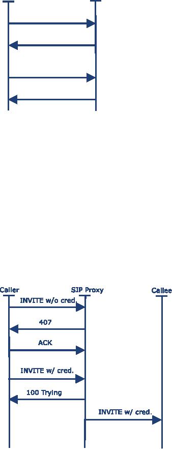
4.3.2.3.2
Invite authentication
Authentication
of INVITE
requests
is not really required, but it is a
good practice to do so. A
SIP
Proxy
Server can only challenge
requests that are coming
from users belonging to an
administrative
domain that the proxy server
is responsible for.This means
that a proxy
responsible
for,
e.g., the iptel.org
domain
can challenge only requests
that have iptel.org in
the From
header
field.
Requests
coming from foreign users
can not be challenged
because foreign users
usually do not
have
a username and password
registered at this server.
Requiring authentication would
make
incoming
calls from foreign users
impossible.
Figure
4.10 is a call flow of
challenged INVITE.
Figure
4.10 INVITE
with
authentication
P.81

[IP
Telephony Cookbook] /
Setting Up Basic
Services
~
4.4.
Examples
This
section lists some examples
of how a zone setup could
look like, depending on
the
requirements.
~
4.4.1.
Example 1: Simple use of IP Telephony like legacy
telephony
Assumption: an
institution currently using a PBX
with internal numbers of four digits
length.
There
are telephone numbers from
6000 to 6999 available for
IP Telephony.There are no
requirements
regarding authentication. Because only
calls into the PSTN
will be billed, the
PBX
is
the only place where billing
will take place.There are no
special requirements
regarding
availability
and there is no demand for
IP Telephony research.
Components:
any
kind of IP Telephony server
(H.323 Gatekeeper or SIP Proxy),
even
productions
using proprietary protocols are
usable.The gateway must be
able to translate
signalling
between the protocol that
the server uses and
the PBX.The protocol to the
PBX
usually
uses one of the protocols
described in Section
5.1.1.
Structure:
See
Figure 4.11.
Call
Routing: the
PBX is configured to route
every call to a number, starting
with 6, to the
gateway.The
IP Telephony server either has
the gateway as a default
route for
unknown/unregistered
targets or is configured to route
every call to a number that
does not start
with
6 to the gateway too.The
gateway can either be
configured to always route a
call from one
side
to the other or needs to
have a configuration similar to the IP
Telephony server.
Authentication:
authentication
on the IP-side is either done
using the H.323 or
SIP
authentication
mechanisms or can be done on
the link layer. In the
latter case, a
telephone
number
is bound to a specific port or MAC
address.
Billing:
the
billing mechanisms that were
already in use for PBX
calls can be used for
IP
Telephony
as well as all outgoing calls
passing the PBX.
default
-> PSTN
6xxx
->IP
Billing
Legacy
PBX
Gateway
IP
telephony
PSTN
server
Figure
4.11 Example of simple IP
Telephony
P.82
[IP
Telephony Cookbook] /
Setting Up Basic
Services
The
solution described allows an easy
integration of IP Telephony into a PBX
world.The
advantage
of this solution compared to just more
legacy phones is that IP
Telephony allows more
flexibility
regarding the endpoints,
allowing both hard and
software phones that may
even be
connected
by wireless LAN (depending on the
authentication mechanisms
used).
The
disadvantage of this solution is that it
relies heavily on the PBX,
which remains the
core
element
of the infrastructure. If there is
demand for more IP Telephony
accounts, more
numberblocks
must be available.To free
such a block requires giving
legacy phone users
new
numbers.The
solution also does not make
use of the Internet for
long-distance calls or select
an
IP
Telephony service provider.
~
4.4.2
Example 2: An example of complex, full-featured IP
Telephony
Assumption:
a university
with multiple locations, a
shared, unstructured dialling
space has a need
for
both SIP and H.323. It
should be possible to test
new IP Telephony server
firmware before
installing
it in the production network.To stretch
this idea further, an additional
requirement is
that
the IP Telephony system has to be divided
into three logical networks: a production
network
(the
telephone system for 90% of
all employees), a testing
network to run new firmware
versions
before
deploying them in the production
network, and a research
network for IP Telephony-
related
research work. Obviously, the networks
differ in reliability, having high
reliability
requirements
in the production network and
nearly none in the research
network.
A
daring user might decide to
participate in the testing
network without changing his
phone
number
or using a second
phone.
Components: to be
able to do IP Telephony research on
standardised protocols, the
research
network
runs either an H.323
Gatekeeper or a SIP Proxy.The production
network runs a
redundant
server that supports H.323
as well as SIP.The testing
network uses the same
server
model,
without redundancy.The gateway is
either an H.323/PSTN or SIP/PSTN
gateway.
A
RADIUS server stores all
valid users (names and
numbers) along with their
password.The
billing
records can be written by
the PBX and the IP
Telephony server, e.g.,
using a SQL server.
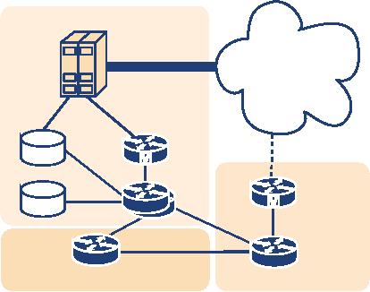
Structure:
Figure
4.12 describes how the
servers are organised.There is an
H.323 Gatekeeper or
SIP
Proxy for each logical
network.Which logical network an endpoint
belongs to is simply
defined
by which server it is registered
with, and is independent
from the physical
network
structure.To
participate in testing of new
features, the endpoint of the
user need only be
configured
to register on the server
using the new firmware
version.
Call
Routing: routing
decisions are either made
using a shared database (see
Section 4.1.1.1.3)
or
by routing calls to external targets,
via the server in the
production network, to the
PBX
gateway.
A server, whose user dials
an internal number, tries other
locally-registered endpoints
first,
before asking the peer
server using the LRQ
mechanism of H.323.
Authentication:
to
achieve authentication, the mechanisms
described in Section 4.3 are
used.
The
authentication back-end is provided by a
RADIUS server that stores
logins and passwords.
P.83
[IP
Telephony Cookbook] /
Setting Up Basic
Services
Billing:
because
external calls are routed through
the PBX, the existing
billing solution may be
used.
If the production network gatekeeper is
able to write billing
records as well, it will
become
the
production billing server when,
sometime in the future, the
university selects an IP Telephony
provider
instead of a PSTN Telco.
Production
network
PSTN
Gateway
Billing
redundant
Gatekeeper
Gateway
RADIUS
Gatekeeper
Gatekeeper
Test
network
Research
network
Figure
4.12 Example of a multi-server IP Telephony
zone
This
scenario is quite complex, but it is the
most flexible. It allows
individual users to move
from
the
legacy telephony world to IP
Telephony, eventually reducing
the PBX to a minimal state.
It is
made
robust by using redundant
servers where necessary. Because
routing decisions are made
on
the
IP-side, this solution qualifies for
communication with external targets
via the Internet or
through
use of an IP Telephony provider.The
decision for open standards
(SIP, H.323) allows
space
for research initiatives and
prevents dependency on specific
vendors.
All
these possibilities come at a price.
Several servers must be bought
and the complex
structure
makes
it harder to trace
errors.
~
4.5
Setting up H.323
services
When
setting up H.323 services,
the basic component to install is a
gatekeeper, in order to
provide
initial functionality to an installed
base of H.323 clients.This basic
functionality entails:
-
in-zone calling among
endpoints;
-
out-of-zone calling
(incoming/outgoing);
-
access to local services
(e.g., gateways, multi-point
conference servers);
-
name resolution during
calls, by H.323 alias or
E.164 number;
-
zone management (authentication,
bandwidth restriction, etc.).
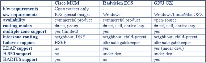
In
this section, guides will be
presented for running the
three most popular
gatekeeper
implementations
that are available today. A
comparison of these gatekeeper
implementations,
based
on their capabilities and
requirements, follows
here:
P.84
[IP
Telephony Cookbook] /
Setting Up Basic
Services
Figure
4.13 Examples of gatekeeper
features
Guides
for basic operation of the
above three gatekeepers
follow, but official documentation
for
these
products should be consulted
when advanced functionality
and features are
required.
~
4.5.1
Using a Cisco Multimedia Conference Manager (MCM
Gatekeeper)
The
Cisco MCM is a software gatekeeper
that runs only on Cisco
router hardware with
special
IOS
images (H.323 feature set).
One the one hand,
this makes it easy to find a
hardware platform
for
running it within most
organisations that use Cisco
hardware, without regard for
underlying
operating
system support. On the other
hand, it does not allow
the flexibility of installation
on
any
available PC-based server. It is a
commercial-grade implementation, mostly
geared towards
VoIP
gateway services and less
towards an open H.323
community of endpoints that
possibly
spans
organisational borders.The MCM supports
either direct mode dialling, or
full routing
mode,
through the use of an included H.323
proxy server. Multiple H.323
zones can be
configured
and controlled on one MCM installation, but
only in combination with
subnet
restriction
rules for groups of
endpoints.The MCM has good inter-zone
routing features with
DNS
gatekeeper discovery as extra
and performs well in a
homogeneous Cisco environment, but
has
only basic support for
RADIUS-based authentication (by
H.323 alias or E.164
and
proprietary
piggy-back password mechanism)
and no support for LDAP
H.350 authentication.
Cisco
MCM VC: Configuring H.323
Gatekeepers is online. 3
~
4.5.1.1.
Installation
Since
the Cisco MCM Gatekeeper is
only an IOS feature (IOS
being the Cisco router
operating
system),
basic IOS installation
procedures are sufficient, assuming a
correct IOS image with
MCM
functionality
has been chosen from the
Cisco support site.Two tools
can help you choose
an
appropriate
IOS for your available router, but
they are only available to
registered users on
the
Cisco
Website:
-
Cisco IOS Upgrade
Planner
-
Cisco Software
Advisor.
Look
for `High-Performance Gatekeeper' under
features and for `IP/H.323'
under feature sets.
IOS
versioning is a subject difficult to
follow. Add to this the
fact, that the MCM has
been
3.
http://sourceforge.net/projects/openh323proxy/
P.85
[IP
Telephony Cookbook] /
Setting Up Basic
Services
undergoing
changes during IOS
development and gatekeeper
features available on different
IOS
versions
vary significantly. Finding the right
IOS-MCM combination to use
for a specific
hardware
configuration can become time
consuming. Always prefer the
latest available IOS
release
for
your hardware, assuming enough RAM is
available to accommodate
it.
~
4.5.1.2
Configuration
Working
with the Cisco IOS command
line interface requires some
experience with basic
commands,
modes of operation, loading
software images and configuration
files, none of which
will
be described here in detail. If
you are not familiar
with Cisco IOS basic
commands, make
sure
you read an introductory
guide by Cisco.To configure
the Cisco MCM, you must
establish
command
line access (telnet) to the
router that runs the
`IP/H.323' feature set and
enter
privileged
(enable command) mode, indicated by
the # at the prompt, before
you can enter
configuration
commands. Enter configuration mode
(config
command)
and then specify
the
`gatekeeper'
section. In this section,
you will need to enter
the MCM configuration commands, as
in
the sample below, which
merely initialises the
gatekeeper operation:
gkp#config
Configuring
from terminal, memory, or
network [terminal]?
Enter
configuration commands, one
per line. End with
CNTL/Z.
gkp(config)#gatekeeper
gkp(config-gk)#zone
local gkp.mydomain.org
mydomain.org
gkp(config-gk)#no
shutdown
gkp(config-gk)#^Z
The
above sample is sufficient to start
gatekeeper services on the router, but a
more detailed
configuration
with comments for a basic
gatekeeper set-up follows.We
have dropped the
command
line prompt for
simplicity.The following commands
can be typed at the
configuration
interface,
as shown above. Note that
all user-specified fields
are indicated as enclosed in
brackets
and
you must customise/replace
them appropriately for your
site.
This
section goes outside the
gatekeeper configuration section as it
relates to general AAA
settings
and
RADIUS server communication.
H.323 endpoint RAS registration
will be checked
against
local
IOS usernames first and then
RADIUS-defined usernames. Accounting
records will be sent
to
the RADIUS server.
!
aaa
new-model
aaa
authentication login h323
local group radius
aaa
accounting connection h323
start-stop group
radius
!
radius-server
host [radius.mydomain.org] auth-port
[1812] acct-port
[1813]
radius-server
key
[radius-server-key-as-defined-in-radius-host]
radius-server
authorisation permit missing
Service-Type
!
P.86
[IP
Telephony Cookbook] /
Setting Up Basic
Services
!
Gatekeeper section
!
gatekeeper
!
!
Local zone info, as
controlled by this
gatekeeper
!
The zone name "myzone" is
for config purposes only
and plays no role,
!
while the domain is
important for endpoints
registering by e-mail
alias,
!
as endpoints that request to be
registered by e-mail address
must match
!
the specified "mydomain.org"
part.
!
The zone prefix is important
for recognising
!
in-zone calls and endpoints,
e.g anything beginning with
0030234
!
zone
local [myzone]
[mydomain.org]
zone
prefix [myzone]
[0030234*]
!
To
set up connectivity with
other zones and gatekeepers,
specify the IP of the
neighbouring
gatekeeper
with a `zone remote' and the
prefix it services with a
`zone prefix' for that
zone.
For
example, if you know a
neighbour gatekeeper handles
all calls with prefix
0030248, include
the
following two lines.
!
zone
remote [neighb1] [neighb1-domain.com]
[neighb1-gkp-ip] 1719
zone
prefix [neighb1]
[0030248*]
!
The
VideNet Gatekeeper, for
example, is the largest
global network of H.323
zones, to which you
can
connect as shown below. Any
calls beginning with 00, are
routed to the VideNet
Gatekeeper.
In
order to accept calls from
VideNet as well, you have to
make your gatekeeper well
known to
the
VideNet hierarchy of gatekeepers
(see https://videnet.unc.edu/)
!
zone
remote videnet3 videnet
137.44.172.248 1719
zone
prefix videnet3 00*
lrq
forward-queries add-hop-count
!
To
force endpoints to register
with a specific h323-id and
password you can use
H.235
(few
endpoints support it) or the
h323-id/password mechanism that
the MCM provides.
!
accounting
security
h323-id
security
password separator /
!
Make
sure no H.323 proxy services
are unintentionally used,
unless proxy functionality is
needed
for
security or QoS reasons.
!
no
use-proxy [myzone] default
inbound-to terminal
no
use-proxy [myzone] default
outbound-from terminal
P.87
[IP
Telephony Cookbook] /
Setting Up Basic
Services
~
4.5.1.3
Operation
Immediately
after configuration, the MCM may
service endpoints, and you
can verify this by
making
a couple of endpoints point to
the gatekeeper for
registration. As soon as the
endpoints
register,
they can be listed with
the following command:
-
show
gatekeeper endpoints
You
may proceed with calling
between the two endpoints by
dialling from the one
the
registered
aliases (name or number) of
the other.The ongoing call
can be listed with
the
following
command:
-
show
h323 gatekeeper
calls
As
an administrator of the gatekeeper,
you may disconnect the
call, or even unregister
an
endpoint.
-
clear
gatekeeper call call-id . .
.
-
unregister
. . .
A
view of the operational
status of the gatekeeper,
such as zones defined,
endpoints registered,
neighbour
gatekeepers defined etc. may
be displayed by the following
command:
-
show
gatekeeper status
Debug
logs of the gatekeeper
operations may be monitored
with the following sequence
of
commands:
terminal
monitor
debug
gatekeeper main 10
debug
h225 asn1
debug
h245 asn1
The
first command makes your terminal capable
of displaying console-style logs
and debugging
output.The
second command produces debugging
output regarding basic
gatekeeper actions.
Obviously,
the last two commands
display information on H.225
and H.245 protocols and
the
output
can be overwhelming, but it may be
the only debugging option
when faced with an
otherwise
intractable problem. Each debugging
option can be stopped by its
equivalent no
debug
and
all debugging output can be
stopped with the no
debug all command.
~
4.5.1.4
Endpoint authentication
The
MCM Gatekeeper implements H.235 authentication, but
its use is limited to
gatekeeper-to-
gatekeeper
and gatekeeper-to-gateway authentication,
because of the very limited
deployment of
H.235
capable endpoints. Cisco has implemented
an alternative method for endpoint
authentication,
which allows for an H.323 or
E.164 alias to carry
(piggy-back) both alias
information
and a password, separated by an
administrator-defined special character,
for example,
a
configuration for this feature is
provided above and once
activated, endpoints must
be
configured
to use alias/password combinations to
register with the
gatekeeper.There are
P.88
[IP
Telephony Cookbook] /
Setting Up Basic
Services
shortcomings
to this method that stem mostly
from the fact that it is a
proprietary solution,
which,
in some cases, exposes clear
text passwords to neighbouring devices
(MCUs, gateways,
gatekeepers).
Of course, the MCM includes
RADIUS support, which might
allow for an IP
address
+ alias identification method to be implemented on
the RADIUS server side, but
such a
solution
imposes restrictions to endpoint
mobility.
~
4.5.1.5
Advanced features
The
Cisco MCM supports RADIUS
authentication and accounting to a
remote RADIUS server.
With
the extensive support of
RADIUS servers to a number of back-ends,
such as databases and
directory
services, this can be an
important feature when
seeking a method of integrating
H.323
access
control with already
deployed services (e.g., dial-up,
LDAP), or a simple way of storing
call-
accounting
information in a database. Also,
the exchange of standard and
vendor-specific
attributes
during the RADIUS negotiation
process allows very fine
control of some
delicate
parameters,
such as call
duration, which
would otherwise be inaccessible to an
external-to-the-
gatekeeper
application. Of course, only
experienced RADIUS administrators
and middleware
developers
can exploit the full
potential of the RADIUS configuration
files and its
back-end
interfaces.The
Cisco MCM supports an alternative method
to neighbour-discovery than
static
neighbour
entries in the IOS configuration. A
DNS-based gatekeeper discovery
mechanism is in
place
that allows the MCM to find
gatekeepers responsible for a
specific domain by checking
for
the
existence of a TXT record in the
domain's DNS zone
information.This can be useful if
a
large
community of users in separate
zones employs e-mail
addresses for dialling.The
gatekeepers
serving
them do not need to have
static knowledge of each other, but can
discover destination
gatekeepers
responsible for a domain through DNS.
Multiple zone support is implemented on
the
MCM
in a way that allows
multiple instances of the
gatekeeper to run within one
router.This
would
have been an excellent feature, if it
could have avoided a major handicap:
endpoint
registration
to a specific gatekeeper has to be guided
by administratively preset IP address
subnet
restrictions.
Interestingly enough, Cisco gateways
can utilise this functionality by
indicating on
their
RRQ messages (by gatekeeper ID
and not by IP address) which
gatekeeper they request
to
be
registered with.
~
4.5.2
Using a RADVISION Enhanced Communication Server (ECS
Gatekeeper)
The
RASVISION ECS is a software-only
gatekeeper that runs on the
WinNT or Win2000
operating
systems, a fact that ties it
to specific remote management
techniques used with all
other
Windows-based
servers. It is a commercial-grade
implementation and it is considered
top-of-the-
line
for the features it provides
and its compatibility even
with the latest H.323
specifications. It is
servicing
large organisations with a
great number of endpoints and
most notably, some of
the
VideNet
global root gatekeepers.The ECS
supports all three modes of
routing: direct, Q.931
routing
and both Q.931 and H.245
routing.The ECS has good inter-zone
routing features with
DNS
gatekeeper discovery and
neighbour gatekeeper LDAP
support as extra. Authentication
is
very
flexible, with the ability
for `predefined' endpoint settings
enforced at registration time
and
LDAP
H.350 support, but no RADIUS
support.
P.89
[IP
Telephony Cookbook] /
Setting Up Basic
Services
~
4.5.2.1
Installation
Installing
the ECS Gatekeeper is a very
simple task, since it
involves merely the execution a
GUI
setup
wizard, which requires no configuration
options.The only potential source of
installation
problems
lies with the fact
that the Windows SNMP
service must already be
installed, before any
service
packs and the ECS
installer are applied. If
this advice, which is listed
in the ECS
documentation,
is ignored, the ECS
installer refuses to proceed
and the only option is to
reinstall
the
operating system itself.
Also,
the administrator of the
host must make sure
that port 80 is free, since
the ECS installs an
HTTP
service on this default port
for configuration management over a
Web interface.The
documentation
also calls for an FTP server
to be running at the same
host, but it only serves
for
downloading
ECS log files, which is
not a required
functionality.
~
4.5.2.2
Configuration
Once
installed, the ECS is ready
to run with default configuration
options.The administrator can
access
the management interface
(see Figure4.14) by launching a
browser and requesting the
local
Web
server (http://localhost).The
interface presents a login
page, where the default
username
and password can be entered
(admin/null-no-password).
After successful login,
the
administrator
is made aware of the fact
that the management tool
can supervise the operation
of a
whole
hierarchy of ECS Gatekeepers (Global
picture), as well as the single
ECS installation
residing
on this host (Local picture).
Proceed with the Local
administrator interface.
Figure
4.14 ECS local administration
entry
Immediately
afterwards, the menus for
the administration of the locally-installed
gatekeeper are
shown,
as below.
There
are four commands to allow
configuration management.The Refresh
button
fills in the
Web
interface forms with configuration data
from the currently-running
ECS Gatekeeper
configuration.The
Upload
button
takes all the changes
made on the Web interface
and applies
them
to the currently-running ECS
configuration.The Import
and
Export
buttons
are used to
store
and retrieve snapshots of
the configuration at different points in
time.
P.90
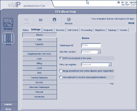
[IP
Telephony Cookbook] /
Setting Up Basic
Services
Figure
4.15 ECS administration
menus
The
rest of the interface is
fairly straightforward, with an
array of configuration tabs (sections),
the
most
important of which are
listed below:
-
Status
tab:
allows view of the current
status of the gatekeeper by indicating
the number of
ongoing
calls and registered
endpoints, as well as bandwidth
usage statistics for in-zone
and out-
of-zone
calls;
-
Settings
tab:
this is where most of the configuration
options are specified, logically
separated
into
a series of thematic categories (Basics,
Calls, Dial Plan,
Supplementary Services,
Logs,
LDAP,
DNS, Security, Alternate Gatekeeper,
Advanced);
-
Endpoints
tab:
allows view and control of
the currently-registered endpoints
with details on
their
aliases (name and number), IP
addresses and online
time.This tab can be used to
predefine
endpoints,
i.e. assign specific aliases
to endpoints that may later
be used for endpoint
identification
during authentication;
-
Services
tab:
allows view and configuration of
the currently declared services. By
default, four
services
exist at installation time
and they are not
activated, since their
prefix setting is
null.
Therefore
they merely exist as
templates for defining basic
services functionality;
-
Call
Control tab:
allows view and control of
the calls in progress and
the setting up of
gatekeeper-initiated
calls between arbitrary
endpoints, with the
Make
call option,
assuming the
gatekeeper
runs in fully-routed mode
(see the Signalling
Models Section
and the Settings
tab,
category Calls
in the
ECS interface);
-
Forwarding
tab:
allows set-up of forwarding rules
based on source and
destination, for
three
cases:
forward on busy, forward on no answer, unconditional
forward;
-
Hierarchy
tab:
allows set-up of a parent
gatekeeper in order to forward Location
Requests
for
cases of unresolved destinations.
User-assigned filters may also be
applied to specify
and
control
the extent of the cases
referred upstream to the
parent gatekeeper.
P.91
[IP
Telephony Cookbook] /
Setting Up Basic
Services
Even
though the ECS Gatekeeper
runs out-of-the-box, you may
want to inspect some of its
basic
settings
and decide whether they
fit the needs of your application.There
are three tabs that
should
be,
at least browsed, through before
proceeding with
operation.
Under
Settings
tab, in
the category Basic, make a
note of the name of the
gatekeeper
(gatekeeper
ID). Also, be aware of the
setting who
can register, where
the choices are everyone
for
no authentication control, predefined
endpoints only for
some authentication control
and
no
endpoints to turn
down all endpoints for
maintenance reasons only.The
choice between `dial
plan
v.1' and `dial plan
v.2' may not be obvious, but
keep in mind that the
second option allows
more
flexibility in hierarchically connected
gatekeeper environments. Once chosen,
it
dynamically
enables extra configuration sections.The
option for DHCP
environment may
be
used
for authentication control, as it
instructs the gatekeeper to
identify endpoints by
previously
seen
IP addresses and H.323
aliases (names) and
authenticate them, based on
this information.The
last
choice, merge
predefined and on-line aliases
upon registration is an
interesting feature,
because
it allows the gatekeeper to
apply extra aliases to
well-known and identified
endpoints,
e.g.,
an endpoint may register with a
name alias only, but the
gatekeeper will attach an
E.164
number
to this endpoint as well.
Under
the Settings
tab, in
the category Calls, be
aware of the routing
mode selection,
as it alter
the
operation of the gatekeeper
dramatically. Direct
mode
employs minimal
communication
between
endpoints and gatekeeper
(RAS messages only), while
Call
set-up routing mode
forces
call
set-up messages to be routed through
the gatekeeper as well (Q.931).The
third mode forces
all
previous messages, as well as
call control messages, to be
routed through the gatekeeper
and not
directly
between the endpoints.The
setting of accept
calls can be
used for maintenance
reasons
to
turn off all calling between
endpoints.
Under
the Settings
tab, in
the category Dialplan,
assuming you have chosen
dial plan version 2,
you
will be able to specify the
stripping of zone prefixes from
destination information of
incoming
calls.This feature may allow
a more user-friendly dial plan, where
in-zone endpoints
use
shorter dial numbers for
dialling and out-of-zone
endpoints use full-length
dial numbers.
In
passing, check the category
Logs
if you
would like to enable logging
for debugging
purposes,
and
the category Billing
to enable
usage statistics and
accounting. Category DNS
will
allow
discovery
of neighbouring gatekeepers through specially
crafted DNS TXT records, but it
seems
to
be compatible only with other
RADVISION gatekeepers. Category
LDAP
will
allow
endpoint
alias data and neighbour
data to be retrieved from
LDAP directory services, as well
as
LDAP-enabled
endpoint authentication.
~
4.5.2.3
Operation
Immediately
after installation, the ECS
may service endpoints, and
you can verify this by
making
a
couple of endpoints point to
the gatekeeper for
registration. As soon as the
endpoints register,
they
appear at the Endpoints
tab.You
may proceed with calling
between the two endpoints
by
dialling
from one of the registered
aliases (name or number) to
the other.The ongoing call
will
appear
in the Call
Control tab. As
an administrator of the gatekeeper,
you may disconnect
the
call,
or even un-register an endpoint from
the respective tab sections.
Logs of gatekeeper
P.92
[IP
Telephony Cookbook] /
Setting Up Basic
Services
operations
may be started through the
Settings
tab,
Logs
subsection
and can be inspected as
text
files
from the
C:\Program
Files\Radvision\ECS\Gatekeeper\Logs directory where
they are
maintained
and rotated after they
reach a certain size.
~
4.5.2.4
Endpoint authentication
The
ECS Gatekeeper implements H.235
authentication, but its use is limited to
gatekeeper-to-
gatekeeper
and gatekeeper-to-gateway authentication,
because of the very limited
deployment of
H.235
capable endpoints.The ECS implements a
method of storing informational data for
well-
known
endpoints (predefined endpoints).This
feature allows for an IP
address + alias
identification
method to be implemented, but such a solution imposes
restrictions on endpoint
mobility.
~
4.5.2.5
Advanced features
The
ECS Gatekeeper is able to
support hierarchies of gatekeepers
(child-parent relationships) in
cases
where many levels of prefixes
must be supported by prefix stripping or
prefix substitution.
For
example, a country-level (parent)
gatekeeper may need to know
all dialled destinations
by
their
12-digit number, while an
organisation-level (child) gatekeeper may
be able to operate
with
just
4-digit numbers most of the
time. In order for the
child gatekeeper to support both long
and
short
dial strings, it needs to
implement prefix stripping.
The
H.450 protocol provides the
implementation framework for supporting,
in H.323, a number
of
features common to conventional
PBX systems.The ECS implements
the H.450 protocol
specifications,
thus enabling many different
types of forwarding: forward
on busy,
forward
on
no
answer,
forward
on reject,
etc.These features are
supported only when the
gatekeeper is in
the
full-routing mode (both call
and control signal
routing).
The
ECS already has support for
retrieving endpoint and neighbour data
from LDAP, but it
does
so
in a proprietary way. New developments in
LDAP-enabled voice-over-IP services
have given
rise
to H.350, the standardised protocol
for storing and retrieving user
settings and
preferences
regarding
H.323 and SIP services.
RADVISION is an active partner in
the committee that
developed
the H.350 standard
(previously known as H.LDAP or
CommObject) and has made
the
commitment
to implement it in the ECS
Gatekeeper.
Until
very recently, gatekeepers
used to be single points of
failure for voice-over-IP
services, as
endpoints
in H.323 can only be
registered with one
gatekeeper.The ECS implements a
special
feature
called `Alternate Gatekeeper', where
two identical ECS Gatekeepers on
two different
nodes
can act in tandem, providing
resilience in gatekeeper services
transparently to the
endpoints.This
is achieved by constant exchange of
information and status
checking between a
master
and a slave gatekeeper, so
that the second one
can assume the role of
the first in case of
failure.
In this case, some of the
calls in progress may be
disconnected, but at least redialling
should
be
successful, without requiring the
endpoints to register to a new
gatekeeper.
P.93
[IP
Telephony Cookbook] /
Setting Up Basic
Services
~
4.5.3
Using an Open H.323 Gatekeeper - GNU
Gatekeeper
The
GNU GK is the most popular
and active in the
development of the open-source
gatekeeper
projects
that stem from the
OpenH323 project efforts. Being an
open-source effort, it benefits
from
availability for many different operating
systems and from flexibility
in configuring a
multitude
of features and interfaces
that are not usually
available in commercial products, and
all
these
with no licensing cost. At
the same time, its
initial installation is made
problematic by lack of
quality
documentation and good versioning
vs. feature-availability support, in
contrast with a very
active
mailing list that users can
seek help with.The GNU GK
supports all three modes
of
routing:
direct Q.931 routing and both
Q.931 and H.245 routing. It
has only basic inter-zone
routing
features, but authentication is very
flexible, with very
configurable RADIUS support
and
LDAP
H.350 support in the
works.
~
4.5.3.1
Installation
Installing
the GNU GK Gatekeeper is not a
simple task, if you decide
to compile the source
of
the
gatekeeper and the two
libraries it requires. However,
this may be your only
option, if support
of
MySQL and LDAP is required,
since the provided precompiled
binaries are lacking it.To
avoid
compilation
of the code, please refer to
the Pre-Built binaries
downloads at the end of
this
section.
In order to compile and
build the GNU GK you will
need both the PWLib
libraries
(version
1.2 or later) and the
OpenH323 libraries (version
1.8 or later). If you are
not familiar
with
those libraries, please
refer to their Web site on
how to build them.
Recommended
versions of the libraries
are PWLib 1.4.11 or later
and Openh323 1.11.7 or
later.
The
order of compiling the
packages is the
following:
-
PWLib (release + debug
version);
-
OpenH323;
-
OpenH323 test application (not
needed, just to make sure
everything works so far);
-
The GNU Gatekeeper itself;
To
compile the GNU Gatekeeper on UNIX, do a
make
debug or
make
opt in the
gatekeeper
source
directory to build debug or release
versions, respectively. Use
make
both to build
both
versions.
Note that you have to
use GCC 2.95.2 or later.
Good practice is to do a make
debugdepend
or make optdepend in the
gatekeeper source directory before
starting actual
compilation
(make
debug or
make
opt). On
Windows, just open and
compile the provided
project
(gk.dsw) for Microsoft
Visual C++ 6.0 or 7.0
(Visual C++ 5.0 is too
old).
The
gatekeeper supports MySQL
and LDAP back-end interfaces
(support for LDAP is still
under
development).The
make
scripts will
look for the MySQL
and OpenLDAP libraries in
standard
places,
but if they are not found,
you will have to explicitly
point to their source
directories by
config
options. If you
do not want MySQL support,
you may set the
NO_MYSQL
environment
before making:
P.94
[IP
Telephony Cookbook] /
Setting Up Basic
Services
$
NO_MYSQL=1 make both
To
leave out LDAP
support:
$
NO_LDAP=1 make both
Or
disable both with
$
NO_MYSQL=1 NO_LDAP=1 make
both
For
gatekeepers with a large
numbers of concurrent calls, the GNU GK
has implemented an
extended
fd_set
structure
that enables the gatekeeper
to support thousands of concurrent calls
in
routed
mode.To enable this feature,
export the LARGE_FDSET
environment
variable to the
maximum
number of file descriptors. For
example:
$
LARGE_FDSET=16384 make
opt
The
GNU GK includes implementation of a
Radius protocol client
that
enables
registration/admission authentication and
authorisation using
Radius
servers. This featured is
enabled by default. To
disable
compilation
of these Radius modules, set
the NO_RADIUS
environment
variable
before making:
$
NO_RADIUS=1 make both
The
GNU GK is able to do accounting.
Currently, only RADIUS and
plain
text
file accounting modules are
available. The accounting is
still
considered
an experimental feature, so it is not
compiled in by default.
To
enable accounting, set the
HAS_ACCT environment variable
before
making:
$
HAS_ACCT=1 make both
Moreover,
there is no special installation
procedure needed. After
compilation, copy the
executable
to a directory of your choice and create
a configuration file for it.There
are several
configuration
examples in the etc/
subdirectory of the source
tree. See the next
section on
Configuration
for further explanations.
For
example, to start the
gatekeeper, a command like this
should work if the configuration
file
(gnugk.ini) is
correct.
$
/usr/sbin/gnugk -c /etc/gnugk.ini -o
/var/log/gnugk.log -ttt
If
you do not wish to compile
the gatekeeper from source,
there are several pre-built
binaries
packages
available. Not all versions
will be made available as
binaries.Therefore the reader
will
have
to check what is
available.
Regarding
Red Hat packages, you
will have to download the
RPMs and enter the
following
command
as root, substituting in the name of
the file you wish
downloaded.
$
rpm -Uvh
gnugk-x.x.x.rpm
P.95
[IP
Telephony Cookbook] /
Setting Up Basic
Services
Regarding
the Debian packages, you can
install the gatekeeper by using
the following command
as
root:
$
apt-get install
openh323gk
~
4.5.3.2
Configuration
The
behaviour of the gatekeeper is completely
determined by the command line options at
run
time
and the specified configuration file.
Some command line options
may override settings in
the
configuration
file. In order to avoid confusion, it is
common practice to keep all
the configuration
options
in the configuration file and
start the GNU GK with the
following command:
$
[/usr/sbin/]gnugk -c /etc/gnugk.ini -o
/var/log/gnugk.log -ttt
Here
we provide a sample configuration file
with the most important
options for setting up
basic
services
and their relative
explanation. Note that all
user-specified fields are
indicated as
beginning
with `my' and you
must customise/replace them
appropriately for your
site.
#Two
lines in order to be able to
telnet your GK on a specific
port
#(the
default is port 7000)
#(the
authorisation rules are
detailed in the [GkStatus::Auth]
section)
[Gatekeeper::Main]
Fourtytwo=42
#name
of your GK
Name=my-GnuGK
#Network
information
#Specify
the network interfaces of
the gatekeeper
#By
default the gatekeeper will
detect the interfaces
#of
your host
automatically
Home=my-ip-address
#information
about the parent GK in order
to forward LRQ
#for
out-of-zone calls
[RasSrv::Neighbors]
[neighbour-name]=my-ip-address:my-port;my-prefix-of-the-neighbour
#define
some features on LRQ and
LCF
[RasSrv::LRQFeatures]
#The
gatekeeper replies with LCFs
containing
#the
destinationInfo and destinationType
fields,
#the
registered aliases and the
terminal type of the
destination endpoint
#The
neighbor gatekeeper can then
save the information
#to
suppress later LRQs
#However,
some vendors' gatekeepers
misuse the
information,
#thus
resulting in interoperability
problems
#set
it to 0 if you encounter problems
with a third-party GK
P.96
[IP
Telephony Cookbook] /
Setting Up Basic
Services
IncludeDestinationInfoInLCF=0
#Include
a NonStandardParameter in LRQs
#to
be compatible with Cisco
gatekeepers
CiscoGKCompatible=1
#If
hopCount has reached 0, the
gatekeeper shall not forward
the message
ForwardHopCount=10
#route
mode section
[RoutedMode]
#Enable
the gatekeeper routed mode,
as opposed to the direct
mode
GKRouted=1
#Route
the H.245 control channel,
only takes effect if
GKRouted=1
H245Routed=1
#Some
endpoints send h245Address in
the UUIE of Q.931
#even
when h245Tunnelling is set to
TRUE
#This
may cause interoperability
problems, avoid setting this
option to 1
RemoveH245AddressOnTunnelling=1
#The
gatekeeper could tear down a
call by sending
#RAS
DisengageRequest to endpoints
#Some
bad endpoints just ignore
this command, with this
option turned on,
#the
gatekeeper will send
#Q.931
Release Complete instead of
RAS DRQ to both
endpoints
#to
force them to drop the
call
DropCallsByReleaseComplete=1
#Setting
this parameter to 1 makes
the gatekeeper
#to
always send Release Complete
to both endpoints
#before
closing the call when it
receives DRQ from one of
the parties
SendReleaseCompleteOnDRQ=1
#Authorisation
rules for telnet
access to port
#(the
default is port 7000)
[GkStatus::Auth]
#allow
only specific
addresses
rule=regex
#
- we are allowing the IP
addresses 192.168.1.*
regex=^(192\.168\.1\.[0-9]+)
default=forbid
#if
you want to allow everybody,
comment the previous lines
and ...
#rule=allow
~
4.5.3.3
Operation
There
are a number of ways to monitor
the operation of the GNU GK.
A command-line (telnet)
interface
is provided, which is installed by
default and allows
monitoring of endpoints
registrations
and call requests. It also
accepts unregistration
commands
for specific
endpoints,
call
clearing and even reloading
of the configuration file, having
inserted the following lines
in the
configuration
file:
P.97
[IP
Telephony Cookbook] /
Setting Up Basic
Services
[Gatekeeper::Main]
Fourtytwo=42
[GkStatus::Auth]
rule=allow
we
can telnet to the GNU GK
machine on the port
specified in the
configuration
file (the default is port
7000):
me@mypc>
telnet gnugk-ip-address
7000
There
are a number of commands that
can be issued in this telnet
session: type help
to see a list
of
them.
Most commands are easy
and intuitive and there is
no need to explain them further.To
end
the
telnet session with the
gatekeeper, type quit
and
hit Enter.
Moreover,
there are two Graphical
User Interface (GUI)
front-ends for the
gatekeeper in order to
monitor
and visualise the
operations:
-
Java GUI:This allows you to
monitor the registrations
and calls that go through
the gatekeeper.
A
right-click on a button gives
you a popup menu for
each endpoint.This GUI works with
Java
1.0 built into most
Web browsers;
-
GkGUI: A new standalone Java
program. It requires Java 1.4.The
GkGUI is released
under
GNU
General Public
License.
~
4.5.3.4
Endpoint authentication
The
GNU Gatekeeper supports all
three RASIUS, MySQL and
LDAP back-end
interfaces
(LDAP
is still under development)
for registration (RRQ) and
admission (ARQ)
authentication
and
authorisation mechanisms.This is obviously a
very complex as well as
flexible environment in
which
to implement authentication and
authorisation methods. H.235 is
supported, but, more
commonly,
ad hoc authentication methods
are used, such as the IP
address + alias
identification
method
on the RADIUS server side.
Special credit-time or duration
restricted calling applications
can
be deployed on the GNU GK,
assuming sufficient administrator man/hours
can be spared.
Please
refer to [Gatekeeper::Auth] and
the following configuration sections on
the manual Web
page
for a more detailed configuration
descriptions of such
features.
~
4.5.3.5
Advanced features
The
GNU GK Gatekeeper incorporates an excellent
combination of the features of
the Cisco
MCM
and the RADVISION ECS, in a
very flexible environment, being
able to support
hierarchies
of gatekeepers (child-parent relationships) in
cases where many levels of
prefixes must
be
supported by prefix stripping or prefix
substitution (please refer to
the
[Endpoint::RewriteE164]
configuration section). Moreover the GNU GK implements
resilience-
features
such as `Alternate Gatekeeper'
support (configuration available through
the
[Gatekeeper::Main]
configuration section), where two identical GNU GK
Gatekeepers on two
different
nodes can act in tandem,
providing resilience in gatekeeper
services transparently to
the
endpoints.
Since it is an open-source project, its
value per cost ratio is very
high, but the
command-line
interfaces it provides are
not for the faint-hearted
and if you do make the
choice,
P.98
[IP
Telephony Cookbook] /
Setting Up Basic
Services
be
prepared to spend many hours
over out-dated documentation and
recompilations of new
code-fixing
releases.
~
4.6
Setting up SIP
services
~
4.6.1
Operation of SIP Servers
~
4.6.1.1
Recommended Operational
Practices
Operation
of a SIP server is not
always an easy task. Server
administrators face many
challenges of
broken
or misconfigured user agents,
network and host failures,
hostile attacks and other
stress-
makers.
All such situations may
lead to an operational failure. It is
sometimes very difficult
to
figure
out the root reason of a
failure, particularly in a distributed environment
with many SIP
components
involved. In this section, we share
some of our practices and
refer to tools which
have
proven
to make the life of
administrators easier.
4.6.1.1.1
Message logging.
Frequently,
operational errors are
discovered or reported with a
delay. Users frustrated by an
error
frequently
approach administrators and
scream "even though my SIP
requests were absolutely
OK
yesterday,
they were mistakenly denied
by your server". If administrators do not
record all SIP
traffic
at their site, they will
not be able to identify the
reason for the problem.We
recommend
that
site operators record all
messages passing their site
and keep them stored
for some period of
time.They
may use utilities such as
ngrep
or
tcpdump.
4.6.1.1.2
Real-time traffic
watching.
Looking
at SIP messages in real-time may
help to gain understanding of
problems.Though there
are
commercial tools available, using a
simple, text-oriented tool
such as ngrep is sufficient for
the
job,
thanks to SIP's textual
nature.
Example
4.1 Using ngrep
In
this example, all messages
at port 5060 which include
the string bkraegelin
are
captured and
displayed.
[jiri@fox
s]$ ngrep bkraegelin@ port
5060
interface:
eth0
(195.37.77.96/255.255.255.240)
filter:
ip and ( port 5060 )
match:
bkraegelin@
#
U
+0.000000 153.96.14.162:50240 ->
195.37.77.101:5060
REGISTER
sip:iptel.org SIP/2.0.
Via:
SIP/2.0/UDP 153.96.14.162:5060.
From:
sip:bkraegelin@iptel.org.
To:
sip:bkraegelin@iptel.org.
Call-ID:
0009b7aa-1249b554-6407d246-72d2450a@153.96.14.162.
Date:
Thu, 26 Sep 2002 22:03:55
GMT.
CSeq:
101 REGISTER.
Expires:
10.
P.99
[IP
Telephony Cookbook] /
Setting Up Basic
Services
Content-Length:
0.
.
#
U
+0.000406 195.37.77.101:5060 ->
153.96.14.162:5060
SIP/2.0
401 Unauthorised.
Via:
SIP/2.0/UDP 153.96.14.162:5060.
From:
sip:bkraegelin@iptel.org.
To:
sip:bkraegelin@iptel.org.
Call-ID:
0009b7aa-1249b554-6407d246-72d2450a@153.96.14.162.
CSeq:
101 REGISTER.
WWW-Authenticate:
Digest realm="iptel.org", \
nonce="3d9385170000000043acbf6ba...",
algorithm=MD5.
Server:
Sip EXpress router(0.8.8
(i386/linux)).
Content-Length:
0.
Warning:
392 127.0.0.1:5060 "Noisy
feedback tells: pid=31604
".
4.6.1.1.3.Tracing
Errors in Server
Chains.
A
request may pass any number of
proxy servers on its path to
the destination. If an error
occurs
in
the chain, it is difficult
for upstream trouble-shooters
and/or users complaining to
administrators
to learn more about error
circumstances.
A
nice utility for debugging
server chains is sipsak, SIP
Swiss Army Knife, a trace-route-like
tool
for
SIP developed at iptel.org.
It allows you to send an
OPTIONS request with
low,
increasing
Max-Forwards
header-fields
and follow how it propagates
in the SIP network. See
its
Webpage
at http://sipsak.berlios.de/
.
Example
4.2 Use of sipsak for
Learning SIP Path
[jiri@bat
sipsak]$ ./sipsak -T -s
sip:7271@iptel.org
warning:
IP extract from warning
activated to be more
informational
0:
127.0.0.1 (0.456 ms) SIP/2.0
483 Too Many
Hops
1:
?? (31.657 ms) SIP/2.0 200
OK
without
Contact header
Note
that in this example, the
second-hop server does not
issue any warning header
fields in
replies
and it is thus impossible to
display its IP address in
sipsak's output.
4.6.1.1.4
Server status
monitoring.
It
is essential for solid
operation to monitor server
status continuously.Two tools
have been used
for
this purpose. Sipsak does a
great job of `pinging' a
server, which may be used
for alerting
administrators
of unresponsive servers.
Monit
is a server-watching utility which
alerts administrators when a
server dies.
P.100
[IP
Telephony Cookbook] /
Setting Up Basic
Services
4.6.1.1.5
Dealing with DNS.
The
SIP standard leverages DNS.
Administrators of SIP servers should be
aware of the impact of
DNS
on a server's operation. A server's
attempt to resolve an un-resolvable
address may block
the
server's
process for a time, in the
order of seconds.To be surer
that the server does
not stop
responding
due to being blocked by
DNS-resolving, the following
practices are
recommended:
-
Start a sufficient number of child
processes. If one is blocked,
the other children will
keep
serving;
-
Use DNS caching. For
example, in Linux, there is an
nscd daemon available for
this purpose;
-
Process transactions statefully if
memory allows.That helps to absorb
retransmissions without
having
to make DNS queries for
each of them.
~
4.6.2
SIP Express Router
SIP
Express Router (SER) is an
industrial-strength, free VoIP
server based on the
Session
Initiation
Protocol (SIP, RFC3261). It is engineered to power IP
Telephony infrastructures up to
large
scale.The server keeps track
of users, sets up VoIP
sessions, relays instant
messages and creates
space
for new plug-in
applications. Its proven interoperability
guarantees seamless integration
with
components from other
vendors, eliminating the risk of a
single-vendor trap. It has
successfully
participated in various interoperability
tests along with products of
other leading SIP
vendors.
~
4.6.2.1
Getting SIP Express
Router
SIP
Express Router is available
for download from
BerliOS
The
newest release can be found in
the folder /latest.
~
4.6.2.2
Installation (From binary
packages)
4.6.2.2.1
Supported architectures
The
following architectures are
supported by SER:
Linux/i386;
Linux/armv4l;
FreeBSD/i386;
OpenBSD/i386;
Solaris/sparc64;
NetBSD/sparc64
(For
other architectures, the
Makefiles
might
need to be edited).There are
various configuration
options
defined in the Makefile
and
Makefile.defs.
4.6.2.2.2
Requirements
*
gcc
or icc : gcc >= 2.9x; >=
(3.1
recommended. It will work
with older version but it
might
require
some options tweaking for
best performance.)
P.101
[IP
Telephony Cookbook] /
Setting Up Basic
Services
*
bison
or yacc (Berkeley
yacc)
*
flex
*
GNU
make (on
Linux this is the standard
make, on
FreeBSD and Solaris is
called gmake)
*
sed
and
tr
(used in
the make
files)
*
GNU
tar (gtar
on
Solaris) and gzip
if you
want make
tar to
work.
*
GNU
install or
BSD
install (on
Solaris ginstall) if you
want make
install,
make
bin,
and
make
sunpkg to
work.
*
mysql
if you
need MySQL support.
*
apache
(httpd) if you
want serweb support
*
PHP,
MySQL-PHPfor
serweb support
*
libmysqlclient
and
libz
(zlib) if you
want MySQL support (the
MySQL module)
*
libexpat
if you
want the Jabber gateway
support (the Jabber
module)
4.6.2.2.3
Install the packages:
Example:
/root>rpm
-i ser-08.11-1.i386.rpm
Packages
for other popular distributions
are available, and can be
installed using the
appropriate
package
manager for that
distribution.
On
many platforms you can
start the ser service
using:
/etc/init.d/ser
start
Red
Hat-based systems will
use:
/etc/rc.d/init.d/ser
start
That
will start the server
with the default configuration.You
can try to register your SIP
user
agent
(for example, MS Messenger) with
the server, place first
calls as well as send
instant messages
to
other users registered with
this server.
The
default configuration is very limited.
Its purpose is to allow the
starting to start the
server
easily
and to test the basic
functionality.The default configuration
does not include
authentication,
the persistence of the user
location database and many
other important
features.
~
4.6.2.3
MySQL setup
To
install support for a MySQL
database, you will need to
download the package ser-mysql,
which
is available from the same
location from which you
downloaded SIP Express
Router.This
package
contains scripts to create
the required database and
establish permissions
for
preconfigured
accounts. A recent release of
MySQL is recommended.You should
definitely use
version
higher than 4.0. Earlier
versions may have problems
with the syntax required to
set
permissions
in the database.
If
you do not already have a
copy of MySQL installed, download it
from http://www.mysql.com
or
check out your Linux
distribution. Many popular
Linux packages come with
the MySQL
server
pre-packaged.
P.102
[IP
Telephony Cookbook] /
Setting Up Basic
Services
Once
you have the MySQL
server installed and
running, execute
/usr/sbin/ser_mysql.sh
create
That
will create database `ser'
and all the tables
that are required by
SER.
You
can verify that the
database has been created
and correct permissions
assigned by using the
MySQL
management tool and these
steps:
Mysql>
select * from user;
|
Host
|
User
|
Password
|
Select_priv
|
...
|%
|
ser
|
4e633cf914a735a0
|N
|
...
|
localhost
|
ser
|
4e633cf914a735a0
|Y
|
...
|%
|
serro
|
7cb73a267cb7bd5f
|N
|
...
|
localhost
|
serro
|
7cb73a267cb7bd5f
|Y
|
...
The
above results show that
the two users, ser
and serro, have been
created and granted
the
permissions
needed to access the
database. Note that, in the
above example, the
permissions have
been
modified to deny access to
these accounts from any
system (%) other than
the local host.
mysql>
connect ser;
Connection
id:
294
Current
database: ser
mysql>
show tables;
+-----------------+
|
Tables_in_ser
|
+-----------------+
|
acc
|
|
active_sessions |
|
aliases
|
|
config
|
|
event
|
|
grp
|
|
location
|
|
missed_calls
|
|
pending
|
|
phonebook
|
|
reserved
|
|
silo
|
|
subscriber
|
|
version
|
+-----------------+
14
rows in set (0.00
sec)
mysql>
select * from
subscriber;
|
phplib_id
|
USERNAME | PASSWORD | FIRST_NAME |
...
|
4cefa7a4d3c8c2dbf6328520bd873a19 |
admin
|
heslo | first
|
...
P.103
[IP
Telephony Cookbook] /
Setting Up Basic
Services
The
previous query shows that
you have one user
account defined and it has
administrator
privileges.
Users with administrator
privileges will be allowed to
user the admin interface
of
Serweb.
Another
account needs to be the
administrator for your realm.That will be
done later.
~
4.6.2.4
Configuration
4.6.2.4.1
Overview
This
section demonstrates simple
examples of how to configure
the server's behaviour using
the
SER
request routing language.
All configuration scripts follow
the SER language syntax,
which
dictates
the following section
ordering:
-
Global
configuration parameters: these
values affect the behaviour
of the server such as
port
number on which it will be listening, the
number of spawned children processes, and
log
level
used for the syslog;
-
Module
loading: these
statements link external modules,
such as transaction
management
(tm) or
stateless UA server (sl)
dynamically;
Note:
If modules depend on each other,
then the depending modules
must be loaded after
modules
on which they depend.We
recommend loading first modules
tm
and
sl
because
many
other
modules (auth,
usrloc, acc, etc.)
depend on them:
-
Module-specific
parameters: determine
the behaviour of modules.
For example, it is
possible
to configure a database to be used by
the authentication module;
-
One
or more route blocks: the
route blocks contain the
request processing logic,
which
includes
built-in actions as well as
actions exported by modules;
Optionally,
if modules supporting reply
processing (currently only tm) are
loaded, one or more
failure_route
blocks
containing logic are triggered by
received replies. Restrictions on use
of
actions
within the failure_route
blocks
apply (see SER Administrators' Guide
for more details).
4.6.2.4.2
Default configuration
script
The
configuration script, ser.cfg, is a
part of every SER
distribution and defines the
default
behaviour
of the server. It allows
users to register with the
server and have requests
proxied to
other
users registered at the same
server as well as to other
SIP servers.
After
performing routine checks, the
script looks whether an
incoming request is for the
served
domain
(administrative domain). If this is true
and the request is REGISTER,
SER
acts as a
SIP
registrar
and updates the user
location database. Optionally, it
verifies the user's identity
first to
avoid
unauthorised contact manipulation.
Non-REGISTER
requests
for served domains are
then processed using the
user location
database.
If a contact is found for a
Requested-URI, script execution proceeds
to stateful
forwarding,
a negative 404
reply is
generated otherwise. Requests
targeted outside the
served
domain
are always statefully
forwarded.
P.104
[IP
Telephony Cookbook] /
Setting Up Basic
Services
Note
that the default configuration
settings, as set by this
simple script, have several
limitations. By
default,
authentication is turned off to avoid
dependency on MySQL. Unless it is turned
on,
anyone
can register using any
name and hijack someone
else's calls.
Even
if authentication is turned on, there is no
relationship between, authentication
username and
the
address of record (see
Section 2.2.2.2.3).That means, for
example, that a user
authenticating
himself
correctly with a `john.doe id',
may register contacts for
`gw.bush'. Site policy may
wish to
mandate
that the authentication ID
must be identical to the username
claimed in the To
header
field.The
auth
module
contains action called
check_to
that
can be used to enforce such
a
policy.
No
dial plan is implemented. All
users are supposed to be
reachable via the
user-location database.
The
script assumes users will be
using the server's hostname
as the domain part of the
address of
record.
If users wish to use another
name (domain name for
example), this must be set
using the
alias
options.
If
authentication is turned on by un-commenting-related configuration
options, the server
will
assume
that the back-end
authentication database contains
the password in clear-text
form
(another
option is storing HA1 strings
for the digest authentication, but
the strings must be
generated
for every administrative domain of
the server
separately).
Example
4.3 Example of a default configuration
script
#
#
simple quick-start config
script
#
#
----------- global configuration
parameters
------------------------
debug=3
#
debug level (cmd line:
-dddddddddd)
fork=yes
log_stderror=no
# (cmd line:
-E)
/*
Uncomment these lines to
enter debugging mode
fork=no
log_stderror=yes
*/
check_via=no
#
(cmd. line: -v)
dns=no
#
(cmd. line: -r)
rev_dns=no
#
(cmd. line: -R)
port=5060
children=4
fifo="/tmp/ser_fifo"
#
------------------ module loading
----------------------------------
P.105
[IP
Telephony Cookbook] /
Setting Up Basic
Services
#
Uncomment this if you want
to use SQL database
#loadmodule
"/usr/local/lib/ser/modules/mysql.so"
loadmodule
"/usr/local/lib/ser/modules/sl.so"
loadmodule
"/usr/local/lib/ser/modules/tm.so"
loadmodule
"/usr/local/lib/ser/modules/rr.so"
loadmodule
"/usr/local/lib/ser/modules/maxfwd.so"
loadmodule
"/usr/local/lib/ser/modules/usrloc.so"
loadmodule
"/usr/local/lib/ser/modules/registrar.so"
loadmodule
"/usr/local/lib/ser/modules/textops.so"
#
Uncomment this if you want
digest authentication
#
mysql.so must be loaded
!
#loadmodule
"/usr/local/lib/ser/modules/auth.so"
#loadmodule
"/usr/local/lib/ser/modules/auth_db.so"
#
----------------- setting module-specific
parameters ---------------
#
-- usrloc params --
modparam("usrloc",
"db_mode",
0)
#
Uncomment this if you want
to use SQL database
#
for persistent storage and
comment the previous
line
#modparam("usrloc",
"db_mode", 2)
#
-- auth params --
#
Uncomment if you are using
auth module
#
#modparam("auth_db",
"calculate_ha1", yes)
#
#
If you set "calculate_ha1"
parameter to yes (which true
in this
config),
#
uncomment also the following
parameter)
#
#modparam("auth_db",
"password_column", "password")
#
-- rr params --
#
add value to ;lr param to
make some broken UAs
happy
modparam("rr",
"enable_full_lr", 1)
#
-------------------------
request
routing logic
-------------------
#
main routing logic
route{
#
initial sanity checks --
messages with
P.106
[IP
Telephony Cookbook] /
Setting Up Basic
Services
#
max_forwards==0, or excessively long
requests
if
(!mf_process_maxfwd_header("10")) {
sl_send_reply("483","Too
Many Hops");
break;
};
if
(msg:len >= max_len ) {
sl_send_reply("513",
"Message too big");
break;
};
#
we record-route all messages -- to
make sure that
#
subsequent messages will go
through our proxy;
that's
#
particularly good if upstream
and downstream
entities
#
use different transport
protocol
if
(!method=="REGISTER")
record_route();
#
subsequent messages withing a
dialog should take
the
#
path determined by
record-routing
if
(loose_route()) {
#
mark routing logic in
request
append_hf("P-hint:
rr-enforced\r\n");
route(1);
break;
};
if
(!uri==myself) {
#
mark routing logic in
request
append_hf("P-hint:
outbound\r\n");
route(1);
break;
};
#
if the request is for other
domain use UsrLoc
#
(in case, it does not
work, use the following
command
#
with proper names and
addresses in it)
if
(uri==myself) {
if
(method=="REGISTER") {
#
Uncomment this if you want
to use digest
authentication
#
if
(!_authorize("iptel.org", "subscriber"))
{
#
www_challenge("iptel.org",
"0");
#
break;
#
};
save("location");
break;
P.107
[IP
Telephony Cookbook] /
Setting Up Basic
Services
};
lookup("aliases");
if
(!uri==myself) {
append_hf("P-hint:
outbound alias\r\n");
route(1);
break;
};
#
native SIP destinations are
handled using our USRLOC
DB
if
(!lookup("location")) {
sl_send_reply("404",
"Not Found");
break;
};
};
append_hf("P-hint:
usrloc applied\r\n");
route(1);
}
route[1]
{
#
send it out now; use
stateful forwarding as it works
reliably
#
even for UDP2TCP
if
(!t_relay()) {
sl_reply_error();
};
}
4.6.2.4.3
Redirect server
The
redirect example shows how
to redirect a request to multiple
destinations using a 3xx
reply.
Redirecting
requests as opposed to proxying
them is essential to various
scalability scenarios.
Once
a message is redirected, SER
discards all related state
information and is no longer
involved
in
subsequent SIP transactions
(unless the redirection addresses
point to the same server
again).
The
key SER actions in this
example are append_branch
and
sl_send_reply
(sl
module).
The
append_branch
action
adds a new item to the
destination set.The destination
set always
includes
the current URI.The sl_send_reply
action, if
passed SIP reply code
3xx, takes all
values
in
the current destination set
and adds them to the
Contact
header
field in the reply.
Example
4.4. Redirect server
#
#
this example shows use of
ser as stateless redirect
server
#
#
------------------ module loading
----------------------------------
loadmodule
"modules/sl/sl.so"
P.108
[IP
Telephony Cookbook] /
Setting Up Basic
Services
#
-------------------------
request
routing logic
-------------------
#
main routing logic
route{
#
for testing purposes, simply
okay all REGISTERs
if
(method=="REGISTER") {
log("REGISTER");
sl_send_reply("200",
"ok");
break;
};
#
rewrite current URI, which
is always part of destination
ser
rewriteuri("sip:parallel@iptel.org:9");
#
append one more URI to
the destination ser
append_branch("sip:redirect@iptel.org:9");
#
redirect now
sl_send_reply("300",
"Redirect");
}
4.6.2.4.4.
On-Reply processing (forward
on unavailable)
Many
services depend on the
status of messages relayed
downstream, forward
on busy and
forward
on no reply to name
the two most well-known.To
support implementation of
such
services,
SER allows returning to request
processing when the forwarding of a
request fails.When a
request
is reprocessed, new request
branches may be initiated or
the transaction can be
completed at
the
discretion of the script
writer.
The
primitives used are
t_on_failure(r)
and
failure_route[r]{}. If the
t_on_failure
action
is
called
before a request is statefully
forwarded and a forwarding failure
occurs, SER will return
to
request
processing in a failure_route
block.
Failures include: receipt of a SIP
error (status
code
>=
300) from
downstream and the absence
of a final reply within the final
response period.
The
duration of the timer is governed by
parameters of the tm module. fr_timer
is the
duration of
the
timer set for non-INVITE
transactions
and INVITE
transactions
for which no
provisional
response
is received. If the timer
hits, it indicates that a
downstream server is
unresponsive.
fr_inv_timer
governs
time to wait for a final
reply for an INVITE. It is
typically longer than
fr_timer
because
the final reply may take a
long time until the called
party (finds a mobile
phone
in
his pocket and) answers
the call.
In
Example 4.5, failure_route
[1] is
set to be entered in error
using the t_on_failure
(1)
action.
Within
this reply block, SER is
instructed to initiate a new
branch and try to reach
the called party
at
another destination (sip:nonsense@iptel.org).To
deal with the case
when none of the
alternate
destinations succeed, t_on_failure
is set
again. If this case really
occurs, failure_route
[2]
is
entered and a last resort
destination (sip:foo@iptel.org)
is tried.
P.109
[IP
Telephony Cookbook] /
Setting Up Basic
Services
Example
4.5 On-Reply
processing
#
#
example
script showing both types of
forking;
#
incoming
message is forked in parallel
to
#
'nobody'
and 'parallel', if no positive
reply
#
appears
with final_response timer,
nonsense
#
is
retried (serial forking);
than, destination
#
'foo'
is given last chance
#
------------------ module loading
----------------------------------
loadmodule
"modules/sl/sl.so"
loadmodule
"modules/tm/tm.so"
#
----------------- setting module-specific
parameters ---------------
#
-- tm params --
#
set time for which
ser will be waiting for a
final response;
#
fr_inv_timer sets value for
INVITE transactions,
fr_timer
#
for all others
modparam("tm",
"fr_inv_timer", 15 )
modparam("tm",
"fr_timer", 10 )
#
-------------------------
request
routing logic
-------------------
#
main routing logic
route{
#
for testing purposes, simply
okay all REGISTERs
if
(method=="REGISTER") {
log("REGISTER");
sl_send_reply("200",
"ok");
break;
};
#
try these two destinations
first in parallel; the
second
#
destination is targeted to sink
port -- that will make
ser
#
wait until timer
hits
seturi("sip:nobody@iptel.org");
append_branch("sip:parallel@iptel.org:9");
#
if we do not get a positive
reply, continue at
reply_route[1]
t_on_failure("1");
#
forward the request to all
destinations in destination set
now
t_relay();
}
failure_route[1]
{
#
forwarding failed -- try
again at another
destination
append_branch("sip:nonsense@iptel.org");
P.110
[IP
Telephony Cookbook] /
Setting Up Basic
Services
log(1,"first
redirection\n");
#
if this alternative destination
fails too, proceed to
...
t_on_failure("2");
t_relay();
}
failure_route[2]
{
#
try out the last
resort destination
append_branch("sip:foo@iptel.org");
log(1,
"second redirection\n");
#
we no more call t_on_negative
here; if this
destination
#
fails too, transaction will
complete
t_relay();
}
4.6.2.4.5
Accounting
In
some scenarios, like
termination of calls in the
PSTN, SIP administrators may
wish to keep
track
of placed calls. SER can be
configured to report on completed
transactions. Reports are
sent
by
default to the syslog
facility. Support for RADIUS
and MySQL accounting exists
as well.
Note
that SER is by no means
call-stateful. It reports on completed
transactions, i.e., after
a
successful
call set up is reported, it
drops any call-related
state.When a call is terminated, a
transactional
state for the BYE
request is created and forgotten
again after the
transaction
completes.This
is a feature and not a bug.
Keeping the state
information during transactions
only
allows
the achievement of significantly higher
scalability. It is then up to the
accounting
application
to correlate call initiation
and termination
events.
To
enable call accounting,
tm
and
acc
modules
need to be loaded and
requests need to be
processed
statefully and labelled for
accounting.This means that if you
want a transaction to be
reported,
the initial request must
have taken the path
setflag(X),
t_relay
in the
SER script. X
must
have the value configured in
the acc_flag
configuration
option.
Also
note, that, by default, only
transactions that initiate a
SIP dialogue (typically INVITE) visit
a
proxy
server. Subsequent transactions
are exchanged directly between
end-devices, do not
visit
proxy
server and cannot be reported.To be
able to report on subsequent
transactions, you need
to
force
them to visit the proxy
server by turning on record
routing.
Example
4.6 Configuration with
enabled accounting
#
#
example: accounting calls to
numerical destinations
#
#
------------------ module loading
----------------------------------
loadmodule
"modules/tm/tm.so"
loadmodule
"modules/acc/acc.so"
loadmodule
"modules/sl/sl.so"
P.111
[IP
Telephony Cookbook] /
Setting Up Basic
Services
loadmodule
"modules/maxfwd/maxfwd.so"
loadmodule
"modules/rr/rr.so"
#
----------------- setting module-specific
parameters ---------------
#
-- acc params --
#
set the reporting log
level
modparam("acc",
"log_level", 1)
#
number of flag, which will
be used for accounting; if a
message is
#
labeled with this flag,
its completion status will
be reported
modparam("acc",
"log_flag", 1 )
#
-------------------------
request
routing logic
-------------------
#
main routing logic
route{
/*
********* ROUTINE
CHECKS
**********************************
*/
#
filter too old
messages
if
(!mf_process_maxfwd_header("10")) {
log("LOG:
Too many hops\n");
sl_send_reply("483","Too
Many Hops");
break;
};
if
(len_gt( max_len )) {
sl_send_reply("513",
"Wow -- Message too
large");
break;
};
#
Process record-routing
if
(loose_route()) { t_relay(); break;
};
#
labeled all transaction for
accounting
setflag(1);
#
record-route INVITES to make
sure BYEs will visit
our server too
if
(method=="INVITE") record_route();
P.112
[IP
Telephony Cookbook] /
Setting Up Basic
Services
#
forward the request
statefuly now; (we need
*stateful* forwarding,
#
because the stateful mode
correlates requests with
replies and
#
drops retransmissions; otherwise, we
would have to report
on
#
every single message
received)
if
(!t_relay()) {
sl_reply_error();
break;
};
}
4.6.2.4.6
Reporting missed
calls
SER
can report missed calls
via the syslog
facility
or to MySQL. Mysql
reporting
can be utilised
by
SER's complementary Web interface,
Serweb.
Reporting
of missed calls is enabled by
the acc module.There are two
cases, in which you want
to
report.The
first case is when a called
party is offline.The other
case is when a user is online,
but
call
establishment fails.There may be
many reasons for failure
(call cancellation, inactive
phone,
busy
phone, server timer, etc.),
all of them leading to a
negative (>=300) reply
sent to the calling
party.The
acc
module
can be configured to issue a
missed-call report whenever a
transaction
completes
with a negative
status.
The
following configuration fragment reports
a missed call in both cases.The top
half of the
condition
reports on calls missed due
to offline called party
status, using the acc_request
action.
The
action is wrapped in transactional
processing (t_newtran) to
guarantee that reports are
not
duplicated
on receipt of retransmissions.
The
bottom half of the condition
marks transactions to online
users in order to be reported
on
failure.That
is what the setflag
(3)
action is responsible for,
along with the configuration
option
log_missed_flag.This
option configures SER to
report on all transactions,
which were marked
with
flag 3.
loadmodule("modules/tm/tm.so");
loadmodule("modules/acc/acc.so");
....
#
if a call is labeled using
setflag(3) and is missed, it
will
#
be reported
...
modparam("acc",
"log_missed_flag", 3 );
if
(!lookup("location")) {
#
call invitations to off-line
users are reported using
the
#
acc_request action; to avoid
duplicate reports on
request
#
retransmissions, request is processed
statefuly (t_newtran,
#
t_reply)
if
((method=="INVITE" || method=="ACK") &&
t_newtran() ) {
t_reply("404",
"Not Found");
acc_request("404
Not Found");
break;
P.113
[IP
Telephony Cookbook] /
Setting Up Basic
Services
};
#
all other requests to
off-line users are simply
replied
#
statelessly and no reports
are issued
sl_send_reply("404",
"Not Found");
break;
}
else {
#
user on-line; report on
failed transactions; mark
the
#
transaction for reporting
using the same number
as
#
configured above; if the
call is really missed, a
report
#
will be issued
setflag(3);
#
forward to user's current
destination
t_relay();
break;
};
4.6.2.4.7
User aliases
Frequently,
it is desirable for a user to
have multiple addresses in a domain.
For example, a user
with
username `john.doe' wants to be reachable
at a shorter address `john' or at a
numerical
address
`12335', so that PSTN calling
parties with numeric-only
key-pads can reach him as
well.
With
SER, you can maintain a
special user location table
and translate existing aliases to
canonical
usernames
using the lookup action
from the usrloc
module.The
following script
fragment
demonstrates
the use of lookup for
this purpose.
Example
4.7 Configuration of use of
aliases
if
(!uri==myself) { # request not
for our domain...
route(1);
# go somewhere else, where
outbound requests are
processed
break;
};
#
the request is for our
domain -- process registrations
first
if
(method=="REGISTER") { route(3); break;
};
#
look now, if there is an
alias in the "aliases"
table; do not care
#
about return value: whether
there is some or not, move
ahead then
lookup("aliases");
#
there may be aliases which
translate to other domain
and for which
#
local processing is not
appropriate; check again, if
after the
#
alias translation, the
request is still for
us
if
(!uri==myself) { route(1); break;
};
#
continue with processing for
our domain...
...
P.114
[IP
Telephony Cookbook] /
Setting Up Basic
Services
The
table with aliases is
updated using the serctl
tool.The
command serctl
alias add
<alias>
<uri>
adds a
new alias, the command
serctl
alias show <user> prints an existing
alias, and the
command
serctl
alias rm <user> removes
it.
[jiri@cat
sip_router]$ serctl alias
add 1234
sip:john.doe@foo.bar
sip:john.doe@foo.bar
200
Added to table
('1234','sip:john.doe@foo.bar')
to 'aliases'
[jiri@cat
sip_router]$ serctl alias
add john
sip:john.doe@foo.bar
sip:john.doe@foo.bar
200
Added to table
('john','sip:john.doe@foo.bar')
to 'aliases'
[jiri@cat
sip_router]$ serctl alias
show john
<sip:john.doe@foo.bar>;q=1.00;expires=1073741811
[jiri@cat
sip_router]$ serctl alias rm
john
200
user (aliases, john)
deleted
Note
that the persistence of
records needs to be turned on in the
usrloc
module.
All changes to
aliases
would otherwise be lost on server
reboot.To enable the
persistence, set the
db_mode
usrloc
parameter
to a non-zero value.
#
....load module ...
loadmodule
"modules/usrloc/usrloc.so"
#
... turn on persistence --
all changes to user tables
are immediately
#
flushed to mysql
modparam("usrloc",
"db_mode",
1)
#
the SQL address:
modparam("usrloc",
"db_url","mysql://ser:secret@dbhost/ser")
~
4.6.2.5
Operation
4.6.2.5.1
User management
There
are two tasks related to
the management of SIP users:
maintaining user accounts
and
maintaining
user contacts. Both of these
jobs can be done using
the serctl
command-line
tool.
The
complimentary Web interface,
Serweb, can be used for
this purpose as well.
If
user authentication is turned on, which
is highly advisable, user
accounts must be created
before
users
can log in.To create a
new user account, use
the serctl
add
utility with the
username,
password
and e-mail as parameters. It is
important that the environment
variable SIP_DOMAIN
is
set to your domain and matches
the realm values used in
your script.The realm value is used
for
calculation
of credentials stored in the
subscriber database, which
are bound permanently to
this
value.
[jiri@cat
gen_ha1]$ export
SIP_DOMAIN=foo.bar
[jiri@cat
gen_ha1]$ serctl add newuser
secret newuser@foo.bar
MySql
Password:
new
user added
P.115
[IP
Telephony Cookbook] /
Setting Up Basic
Services
serctl
can
also change the user's
password or remove existing accounts
from the system
permanently.
[jiri@cat
gen_ha1]$ serctl passwd
newuser newpassword
MySql
Password:
password
change succeeded
[jiri@cat
gen_ha1]$ serctl rm
newuser
MySql
Password:
user
removed
Typically,
user contacts are automatically
uploaded by SIP phones to
the server during
the
registration
process and administrators do
not need to worry about
them. However, users
may
wish
to append permanent contacts to
PSTN gateways or to locations in
other administrative
domains.To
manipulate the contacts in
such cases, use the
serctl
ul tool.
Note that this is the
only
correct
way to update contacts -- direct
changes of the back-end
MySQL database do not affect
a
server's
memory. Also note, that if
persistence is turned off (usrloc
db_mode parameter
set to 0),
all
contacts will be lost on
server reboot. Make sure
that the persistence is
enabled if you add
permanent
contacts.
To
add a new permanent contact
for a user, call serctl
ul add <username>
<contact>.To
delete
all users' contacts, call
serctl
ul rm <username>.The
command serctl
ul show
<username>
prints
all current contacts of this
user.
[jiri@cat
gen_ha1]$ serctl ul add
newuser sip:666@gateway.foo.bar
sip:666@gateway.foo.bar
200
Added to table
('newuser','sip:666@gateway.foo.bar')
to 'location'
[jiri@cat
gen_ha1]$ serctl ul show
newuser
<sip:666@gateway.foo.bar>;q=1.00;expires=1073741812
[jiri@cat
gen_ha1]$ serctl ul rm
newuser
200
user (location, newuser)
deleted
[jiri@cat
gen_ha1]$ serctl ul show
newuser
404
Username newuser in table
location not found
4.6.2.5.2
Access control (PSTN
gateway)
It
is often important to exercise
some sort of access control.
A typical case is when SER is
used to
guard
a PSTN gateway. If a gateway could
not be well-guarded, unauthorised
users would be able
to
use it to make calls to the
PSTN, inflicting high
costs.
There
are a few issues you
need to understand when
configuring SER for this
purpose. First, if a
gateway
is built or configured to accept
calls from anywhere, calling
parties may easily bypass
your
access
control server and communicate
with the gateway directly.You
then need to enforce,
at
transport
layer, that signalling is
only accepted if coming via
SER and deny SIP
packets coming
from
other hosts and port
numbers.Your network must be
configured not to allow
forged IP
addresses.
Also, you need to turn on
record
routing to assure
that all session requests
will travel
via
SER. Otherwise, calling party's devices
would send subsequent SIP
requests directly to your
gateway,
which would fail because of
transport filtering.
P.116
[IP
Telephony Cookbook] /
Setting Up Basic
Services
Authorisation
(i.e., the process of
determining who may call
where) is facilitated in SER
using
the
group membership concept.
Scripts make decisions on
whether a calling party is authorised
to
make
a call to a specific destination,
based on the user's
membership in a group. For
example, a
policy
may be set up to allow calls
to international destinations, only to
users who are members
of
`int'
group. Before a user's group
membership is checked, his
identity must be
verified.Without
cryptographic
verification of the user's
identity, it would be impossible to
confirm that a calling
party
really is who he claims to
be.
The
following script demonstrates
how to configure SER as an
access control server for a
PSTN
gateway.The
script verifies user
identity using digest authentication,
checks user's privileges,
and
forces
all requests to visit the
server.
Example
4.8 Script for gateway
access control
loadmodule
"modules/sl/sl.so"
loadmodule
"modules/tm/tm.so"
loadmodule
"modules/acc/acc.so"
loadmodule
"modules/rr/rr.so"
loadmodule
"modules/maxfwd/maxfwd.so"
loadmodule
"modules/mysql/mysql.so"
loadmodule
"modules/auth/auth.so"
loadmodule
"modules/auth_db/auth_db.so"
loadmodule
"modules/group/group.so"
loadmodule
"modules/uri/uri.so"
#
----------------- setting module-specific
parameters ---------------
modparam("auth_db",
"db_url","mysql:ser:heslo@localhost/ser")
modparam("auth_db",
"calculate_ha1", yes)
modparam("auth_db",
"password_column", "password")
#
-- acc params --
modparam("acc",
"log_level", 1)
#
that is the flag for
which we will account --
don't forget to
#
set the same one
:-)
modparam("acc",
"log_flag", 1 )
#
-------------------------
request
routing logic
-------------------
#
main routing logic
route{
/*
********* ROUTINE
CHECKS
**********************************
*/
#
filter too old
messages
if
(!mf_process_maxfwd_header("10")) {
log("LOG:
Too many hops\n");
sl_send_reply("483","Too
Many Hops");
break;
P.117
[IP
Telephony Cookbook] /
Setting Up Basic
Services
};
if
(len_gt( max_len )) {
sl_send_reply("513",
"Wow -- Message too
large");
break;
};
/*
********* RR **********************************
*/
/*
grant Route routing if route
headers present */
if
(loose_route()) { t_relay(); break;
};
/*
record-route INVITEs -- all
subsequent requests must
visit us */
if
(method=="INVITE") {
record_route();
};
#
now
check if it really is a PSTN
destination which should be
handled
#
by
our gateway; if not, and
the request is an invitation,
drop it --
#
we
cannot terminate it in PSTN;
relay non-INVITE requests -- it
may
#
be
for example BYEs sent by
gateway to call
originator
if
(!uri=~"sip:\+?[0-9]+@.*") {
if
(method=="INVITE") {
sl_send_reply("403",
"Call cannot be served
here");
}
else {
forward(uri:host,
uri:port);
};
break;
};
#
account completed transactions
via syslog
setflag(1);
#
free call destinations ...
no authentication needed
if
( is_user_in("Request-URI", "free-pstn") /*
free destinations */
|
uri=~"sip:[79][0-9][0-9][0-9]@.*" /* local
PBX */
|
uri=~"sip:98[0-9][0-9][0-9][0-9]") {
log("free
call");
}
else if (src_ip==192.168.0.10) {
#
our gateway does not
support digest
authentication;
#
verify that a request is
coming from it by
source
#
address
log("gateway-originated
request");
}
else {
#
in all other cases, we need
to check the request
against
#
access control lists; first
of all, verify
request
#
originator's identity
if
(!proxy_authorize(
"gateway"
/* realm */,
"subscriber"
/* table name */))
{
proxy_challenge(
"gateway" /* realm */, "0"
/* no qop */ );
P.118
[IP
Telephony Cookbook] /
Setting Up Basic
Services
break;
};
#
authorise only for INVITEs
-- RR/Contact may result in
weird
#
things showing up in d-uri
that would break our
logic; our
#
major concern is INVITE
which causes PSTN
costs
if
(method=="INVITE") {
#
does the authenticated user
have a permission for
local
#
calls (destinations beginning
with a single zero)?
#
(i.e., is he in the "local"
group?)
if
(uri=~"sip:0[1-9][0-9]+@.*") {
if
(!is_user_in("credentials", "local"))
{
sl_send_reply("403",
"No permission for local
calls");
break;
};
#
the same for long-distance
(destinations begin with two
zeros")
}
else if (uri=~"sip:00[1-9][0-9]+@.*")
{
if
(!is_user_in("credentials", "ld"))
{
sl_send_reply("403",
" no permission for LD
");
break;
};
#
the same for international
calls (three zeros)
}
else if (uri=~"sip:000[1-9][0-9]+@.*")
{
if
(!is_user_in("credentials", "int"))
{
sl_send_reply("403",
"International permissions
needed");
break;
};
#
everything else (e.g.,
interplanetary calls) is
denied
}
else {
sl_send_reply("403",
"Forbidden");
break;
};
};
# INVITE to authorised
PSTN
};
# authorised PSTN
#
if you have passed through
all the checks, let
your call go to GW!
rewritehostport("192.168.0.10:5060");
#
forward the request
now
if
(!t_relay()) {
sl_reply_error();
break;
};
}
P.119
[IP
Telephony Cookbook] /
Setting Up Basic
Services
Use
the serctl
tool to
maintain group membership.The command
serctl acl grant
<username>
<group>
makes a user member of a group,
the command serctl
acl show <username>
shows
groups
of which a user is member, and
the command serctl
acl revoke
<username>
[<group>]
revokes a
user's membership in one or
all groups.
[jiri@cat
sip_router]$ serctl acl
grant john int
MySql
Password:
+------+-----+---------------------+
|
user | grp |
last_modified
|
+------+-----+---------------------+
|
john | int | 2002-12-08
02:09:20 |
+------+-----+---------------------+
~
4.6.3
Asterisk
In
this section we will
describe an example configuration of the
Asterisk PBX.We will
focus
mainly
on the configuration of the SIP
part.
~
4.6.3.1
Getting Asterisk
Asterisk
can be downloaded from
http://www.digium.com
~
4.6.3.2
Installation
Download
the tarball
and
untar
it
using:
tar
xvfz asterisk-0.5.0.tar.gz
Compile
the sources:
-
#
cd
asterisk-0.5.0
-
#
make
-
#
make
install
-
#
make
samples
~
4.6.3.3
Configuration
The
configuration files can be found in the
/etc/asterisk
directory.The
most important files
are:
sip.conf
which
contains configuration of SIP user
agent and extensions.conf
which
defines the
dialling
plan.
In
this simple example,
Asterisk is configured to act as a
simple back-to-back user agent. It
will
allow
SIP user agents to register
to it and make calls which
will be routed to an outbound
proxy.
P.120
[IP
Telephony Cookbook] /
Setting Up Basic
Services
The
file sip.conf
contains
the following
settings:
;
;
SIP Configuration for
Asterisk
;
[general]
port
= 5060
;
Port to bind to
bindaddr
= 0.0.0.0
;
Address to bind to
context
= from-sip
;
Default for incoming
calls
;
register
=> asterisk:password@iptel.org/jan
;
Register with a SIP
provider
[iptel]
type=friend
username=asterisk
secret=password
fromdomain=iptel.org
host=iptel.org
[jan]
type=friend
username=jan
;secret=blah
host=dynamic
canreinvite=no
Section
general
contains
some generic settings. Configure
Asterisk to listen on port
5060 and to
listen
on all available interfaces.
Specify context to be from-sip.The
same context must be
later
configured
in extensions.conf
!
The
line beginning with register
instructs
Asterisk to act as a user
agent and register with
the
iptel.org
server as
user asterisk
with
password, password.The
/jan
part
indicates that all
incoming
calls to user asterisk will
be forwarded to user `jan',
registered at the Asterisk
server.
Section
iptel
contains
configuration of a peer. In this case, it
is the iptel.org
proxy
server,
because
we will be using this server
as an outbound proxy. In this section,
the parameter
fromdomain
is
specified, because we want
all outgoing messages to have
this domain in the
From
header
field.
The
last section, jan,
contains credentials and
data for a user that
will be able to register
with the
Asterisk
server. In this case, one
SIP phone is configured with
username jan
and
with an empty
password
and with a phone that
will be registered with the
Asterisk server to receive
calls for
username
jan.
P.121
[IP
Telephony Cookbook] /
Setting Up Basic
Services
The
file extensions.conf
contains
the following settings:
[from-sip]
exten
=> jan,1,Dial(SIP/jan)
exten
=> jan,2,Hangup
exten
=> _3.,1,SetCallerID(jan)
exten
=> _3.,2,SetCIDName(Jan Janak)
exten
=> _3.,3,Dial(SIP/${EXTEN:1}@iptel)
exten
=> _3.,4,Playback(invalid)
exten
=> _3.,5,Hangup
The
first line describes the
context which we have
already configured in sip.conf
.The
following
lines
describe the dialling plan.The
exten
directive
means that the extension of
the call will be
processed.The
first parameter after the
=>
is the
extension. If the extension
starts with an
underscore
then it will be treated as an
expression. Otherwise only an
exact match will be
accepted.
In
the example, the first two
lines match the extension
jan.The
rest of the lines will
match any
extension
starting with digit
3.
The
second parameter is the
preference of the line in
the dialling plan.The last
parameter is the
action
to be executed when the
extension matches.The first line says
that calls with extension
jan
will
be routed to SIP and peer
jan.
Any
extensions beginning with 3 will be
routed to the iptel.org server
using SIP and
username
jan
will be
set as the calling party ID.
If a call fails then
Asterisk will reply with an
error
message.
~
4.6.4
VOCAL
~
4.6.4.1
Overview
The
Vovida Open Communication Application
Library (VOCAL) is an open source
project
targeted
at facilitating the adoption of Voice
over IP in the marketplace.VOCAL provides
the
development
community with software and
tools needed to build Voice
over IP features,
applications
and services.The VOCAL
system is a distributed network of
servers that provides
Voice
Over Internet Protocol (Voice over IP)
telephony services.VOCAL supports devices
that
communicate
using the Session Initiation
Protocol (SIP, RFC3261).VOCAL also
supports
analogue
telephones via residential gateways.VOCAL
supports on-network and
off-network
calling.
Off-network calling enables subscribers
to connect to parties through either
the Internet
or
the Public Switched Telephone
Network (PSTN).
The
basic software in VOCAL
includes a set of SIP-based
servers (Redirect Server, Feature
Server,
Provisioning
Server and Marshal Proxy
Server).This is the stable
development branch of
the
VOCAL
server. Moreover, even if the
following applications are
not included in the current
release
(1.5.0), their source code
remains available in the CVS
archive
http://www.vovida.org/cgi-bin/fom?file=556:
P.122
[IP
Telephony Cookbook] /
Setting Up Basic
Services
-
SIP
to MGCP translator
-
Policy
server
-
Conference
proxy server
-
SIP
to H.323 translator
-
JTAPI
feature server
-
SIP
User Agent (replaced by
SIPset)
-
SNMP/NetMgnt
For
a more detailed overview of the
VOCAL system please refer
to: http://www.vovida.org
~
4.6.4.2
Installation
If
you have a previous
installation of VOCAL that
uses the vocalstart
executable
to run, you must
stop
all servers with vocalstart
stop. Note
that vocalstart
is no
longer used, as of version
1.4.0.
In
order to perform this action
and to install VOCAL, you
must be logged in as root in your
Linux
system.
There
are two options for
downloading and installing VOCAL:
-
Installing from RPM:
-
Download vocalbin-version-x.i386.rpm from
http:/www.vovida.org
Install
the RPM as root, typing rpm
-U
vocalbin-version-x.i386.rpm.
Installing
from source:
Type
the following sequence of
commands:
./configure
make
make
install
You
must become root before
executing make
install.
If
you want to have more
information about compiling
and installing VOCAL please
refer to the
file
BUILD.txt.
~
4.6.4.3
Configuration
To
set up a basic configuration, you
have to use the configuration
script indicated
here:
/usr/local/vocal/bin/allinoneconfigure/allinoneconfigure
Running
the allinoneconfigure
script,
you will be asked a number of
questions.
For
basic services setup, answer
all questions with the
default answers.
After
such a default configuration, an Apache
Web Server has been
reconfigured on your Linux
machine
to provide basic Web-based configuration
(provisioning in VOCAL terms) and
must be
restarted
for this to take
effect.
P.123
[IP
Telephony Cookbook] /
Setting Up Basic
Services
In
order to restart the Apache
Web Server you should
run:
/etc/rc.d/init.d/httpd
restart
When
the Apache Web Server is
restarted you will be able
to use the Web-based
provisioning
of
the VOCAL system. In order
to start provisioning your system you
will have to point a
browser
to.
http://your.server.name/vocal/
You
will be prompted for a password.The
username is vocal. During
configuration, you were
asked
to enter a password or choose to
have one generated for
you. If you have forgotten
the
password
from that step, you
can regenerate one by
running the command:
allinoneconfigure
-r
After
you have run the
allinoneconfigure
script,
make sure that your VOCAL
system is running
typing
the following command:
/usr/local/vocal/bin/vocalctl
status
You
have to make sure that
you are able to see all of
the necessary processes, as
follows:
fs
5080
14957
fs
5085
14955
ms
5060
15002
...
If,
instead of such a list of actively
running servers with the
details of the ports they
are listening
to,
you see vocald
is not
running, then your VOCAL
system is not running
because something
went
wrong in the configuration.
If
your VOCAL system is running,
you can verify your
installation by running the
verifysip
command.
Passing
it the -a option causes
verifysip
to create
two test users, test1000
and
test1001,
and
make
a call from test1000
to
test1001. After
testing, verifysip
will
remove the two
users.You
should
be able to run it with a command
like this:
/usr/local/vocal/bin/verifysip
-a
If
the installation is OK, you
should see the following
text:
VOCAL
basic call test
passed.
P.124
[IP
Telephony Cookbook] /
Setting Up Basic
Services
~
4.6.4.4
Operation
VOCAL
1.5.0 comes with two
provisioning systems. Both work on
the same configuration
data.
The
first, uses a Java application to
configure the system.The
second uses Web-based CGI
scripts,
which
run on the Web server to
configure and control VOCAL.
It can be accessed through your
Web
browser.The Web-based provisioning system
provides simple access to
the most commonly
used
provisioning options for an all-in-one
system.The Java-based application
provides complete
view
to the server's features,
and dial plan
provisioning.
Both
provisioning systems can be used on
the same system, but they
should not be run at
the
same
time.The Web-based provisioning system is
more limited than the
Java-based one, thus
some
tasks
require using the latter.
For tasks other than
those requiring the Java provisioning
system, we
recommend
using the Web-based provisioning
system.The provisioning systems allow
the system
administrators
to work with user and
server data. Administrators can
choose to Add,
View,
Edit
and
Delete
Users, as well
as insert details of the
clients/users allowed access to
the VOCAL
services.
Server
data can be used to
configure services, as well as
install more advanced
features.
~
4.6.4.5
Endpoint authentication
The
server in charge of authentication in
the VOCAL system is the
Marshal Proxy
Server.The
Marshal
Proxy Server supports these
authentication options:
-
No authentication;
-
Access control authentication -
verification of IP address.
-
HTTP Digest authentication -
verification of username and
password.
~
4.6.4.6
Advanced features
There
are a lot of advanced
features that can be
deployed on VOCAL architecture. In
this section,
an
overview of these features is
presented. For a more detailed
explanation please refer to
the
VOCAL
Web pages.
Each
Marshal Proxy Server sends
the start
and
stop
time of a call to the
Call
Detail Record
(CDR)
Server.The CDR Server may forward
the data to 3rd party
billing systems using
the
RADIUS
accounting protocol.
Redirection
of calls, integration with PSTN
gateways and conferencing
are configured and
exploited
using other special kinds of
Marshal Servers.
Support
for both SIP to H.323
Gateways and SIP to MGCP
Gateways is under development
and
the
actual implementation is not
yet ready to be used in a production
environment, even if
improvements
are planned in the near
future.
P.125
[IP
Telephony Cookbook] /
Setting Up Basic
Services
Dial
plans are easily managed by
configuring entries in the provisioning
system GUI.
Redirection
services
and backup servers, as well
as more features like call forwarding
and call blocking
are
carried
out using specialised
servers. Last, but not
least, a voice mail server
is used to deliver
mail
with
attached voice files containing
messages registered to the
users.
~
4.7
Firewalls and NAT
Firewalls
and Network Address
Translation (NAT) affect IP
Telephony signalling
protocols,
making
it impossible to call targets
outside the private or
protected network.While firewalls
and
NATs
often go hand in hand, they
impose two different problems
which are described
here.
~
4.7.1
Firewalls and IP Telephony
Both
SIP and H.323 calls
use a number of different ports, out of
which only the signalling
ports
are
well defined - TCP port
1720 for H.323 and
TCP port 5060 (early
versions of SIP used
5060
UDP
as well).To be able to place
and receive calls to/from
outside the protected
network,
opening
these ports is the minimum
requirement.
After
signalling has started, further channels
are required. H.323 often
uses a separate TCP
connection
for capability exchange
(H.245), which uses dynamically
assigned port
numbers.
Likewise
the RTP media stream
uses dynamically assigned port
numbers on each side.The
only
restriction
that applies to these ports
is that they are in the
port range > 1023.
As
a result, a firewall protected IP
Telephony zone needs either
a firewall that does not
protect
ports
> 1023 or a firewall that is IP
Telephony-aware, meaning that it
monitors all SIP and
H.323
messages
in order to open and close
the required ports on the
fly. A third alternative is to
deploy
an
H.323 or SIP Proxy outside
the zone protected by the
firewall, perhaps in a DMZ,
and
configure
the firewall to allow
communication of endpoints only
with this proxy.This is a
mid-
level
security approach, as it permits the
relatively safe communication
between protected
endpoints
and a trusted proxy server
outside the firewall.This document
does not intend to
give
an
overview of suitable firewall
solutions, so when installing IP
Telephony solutions, ensure
that
your
firewall supports
them.
~
4.7.2
NAT and IP Telephony
Another
problem occurs if your IP Telephony zone
resides in a private network
(no public IP
addresses).
SIP and H.323 use
TCP for signalling, but the
messages carried in the
application layer
contain
IP addresses that are not
recognised by the NAT. In addition,
the H.323 RAS
channel
uses
UDP for transport.This combination
results in the following
problems:
1.
Registration: Consider an endpoint which
lies inside a private
network and registers at a
public
server.Without
being aware of the NAT, it
would try to register with
its private IP
address.
Eventually
the server's reply would
reach the endpoint, but no call
that the server tries to
put
through
using the registered address
will;
P.126
[IP
Telephony Cookbook] /
Setting Up Basic
Services
2.
Call signalling: Some call
signalling messages contain IP
addresses that are necessary
for
subsequent
communication, e.g., the IP
address (and port) to which
media data will be
sent.
Usually,
an endpoint transmits its local
(private) IP address, causing
the communication
partner
to
fail when trying to connect
to that IP address.
One
possible solution is the STUN protocol,
defined in RFC 3489. An endpoint
implementing
this
protocol connects to a public STUN server
to be informed of his public IP
address.The result
of
this query is used as the IP
address to register with at a
remote server.While STUN seems to
be
more
popular in the SIP world,
there is no H.323 endpoint that we
are aware of that supports
this
feature.
Another
possibility is to use a router that is
aware of IP Telephony protocols
and rewrites the IP
addresses
within the application layer
messages, as they are
routed. But this requires
full decoding
and
encoding support for SIP
and/or H.323, which is
simple for the text-based
SIP protocol but
quite
complex for the ASN.1-based
H.323 protocol. In addition, it is always
possible that such a
router
might remove all message
content it does not understand, so
that trying to transport
new
protocol
features through such a
router may inexplicably fail. Such an IP
Telephony router may
come
in the form of an application running on
the NAT router itself -
like the OpenH323Proxy4.
~
4.7.3
SIP and NAT
~
4.7.3.1
Overview
Since
the start of deployment of
SIP-based devices for
Internet telephony, there
have been
problems
with traversing NAT.There
are several reasons why
SIP does not work through
NAT
properly:
-
Addresses used for the
communication and that is
changed by NATs;
-
From its beginning, SIP has been
designed without considering NAT
scenarios.This allows
the
design
of a protocol that is highly scalable but
imposes many restrictions
later;
-
SIP is very flexible so it is
hard to implement SIP
support into NAT
devices;
-
End-to-end communication for
hosts behind two different
NATs is often not
possible.
Many
proposals for NAT traversal
have been created recently,
but none of them works
universally
or
are applicable to all real
world scenarios.The proposals include
Connection Oriented
Media,
STUN,TURN,
SIP ALG and so on.
All
the proposals have been
collected into one single
document which is called ICE.
ICE stands
for
Interactive Connectivity Establishment. It is a
methodology for traversing NAT, but it is
not a
new
protocol. It is a collection of all
previously mentioned attempts to traverse
NAT which work
universally.The
methodology is quite complex and requires
mutual cooperation of all
endpoints
involved
in the communication.
Although
it works universally, such a solution is
hard to implement.This section
describes a
solution
that is based on ICE, but
with a couple of assumptions
and simplifications.That will
result
in a significantly simpler implementation,
which is supported by almost
any SIP devices
available
today and which works in
most real-world
scenarios.
4.
<http://sourceforge.net/projects/openh323proxy/>
P.127
[IP
Telephony Cookbook] /
Setting Up Basic
Services
The
price for the simplifications will be
the use of an RTP relay in
cases where it is not
absolutely
necessary,
but such cases seem to be quite
rare.The simpler solution will
also impose higher
requirements
on SIP devices. Fortunately,
most manufacturers seem to
have implemented all
necessary
features already.
The
scenario, as presented in following
subsections, assumes that
the SIP Proxy is in the
public
Internet
and SIP user agents
are behind NAT.
4.7.3.1.1
Symmetric signalling
One
of requirements laid on SIP
devices that should work
behind NAT is support for
symmetric
signalling.
Normally each SIP user
agent is listening on port 5060
for incoming SIP
traffic.This
port
number is usually advertised in the
Via
header
field so that replies will
come back on the
proper
port and not to the
port from which the
request was sent, and
the port number will
be
also
registered in the registrar so
any subsequent messages will
be sent to 5060 as
well.
When
sending SIP messages, the
user agent is allowed to use
a completely different socket,
which
means
that the source port number
of the outgoing SIP messages
will be different. It will be
not
5060
and usually it is some high
port number assigned by the
operating system.
That
works well when there is no NAT
device along the path, but
it will not work when
the user
agent
is behind a NAT.The reason is
that NATs usually do not
allow any traffic to the
private
network
unless there was a packet
sent from the same IP
and port to the public
Internet.That
means
that if a host with a
private IP address, 192.168.0.1,
wants to receive a packet on
port 5060
from
a host 1.2.3.4 (which is in
the public Internet), it has to first
send a packet with source
port
5060
to host 1.2.3.4.The packet will
create a binding in the NAT
and the NAT box will
forward
replies
from 1.2.3.4 to
192.168.0.1.
The
binding will expire if there is no
traffic for some interval. However, it is
clear that a SIP
user
agent
behind NAT, listening on port
5060, will not be able to
receive any traffic to that
port
unless
it sends a packet through the NAT
with source port
5060.
That
is the principle of symmetric
signalling. In other words,
the SIP user agents,
using symmetric
signalling,
send SIP messages from
the same source port on
which they receive incoming
SIP
messages
(usually 5060).This is the
only that way they
will be able to create a
binding in the NAT
that
will allow incoming SIP
traffic through.
Fortunately,
the vast majority of
developers of SIP devices
seem to understand this, so
almost all
SIP
devices that are available
today support symmetric signalling.That
includes Cisco
phones,
Windows
Messenger, Mitel phones,
Grandstream, Snom, X-lite and
kphone (from version
3.13).
Support
for symmetric signalling is a
must and SIP user
agents not supporting it
will not work
behind
NATs.
4.7.3.1.2
Symmetric media
There
is a similar problem getting media streams through
NATs. Here again, the
party behind
NAT
must send the first media
packet to create a binding,
and open a pinhole in the NAT
box.
P.128
[IP
Telephony Cookbook] /
Setting Up Basic
Services
Similarly,
a user agent behind NAT must
send a media packet with a
source port that is same
as
the
port on which the user
agent expects media from
remote party and which
was advertised in
the
SDP.This is the only that
way media will be able to
pass the NAT in both directions.
In
addition, the remote party
(which is in the public
Internet) must ignore the
contents of SDP
and
send the media, not to
the IP and port which it
received SDP, but to the IP
and port from
which
are media from the
remote party is coming.That
will be the public IP of the
NAT box.
This
approach is called Connection-Oriented
Media and is also known as
Symmetric Media.
It
will work when one
party is behind a NAT and
the other party is in the
public Internet. In
that
case,
the party behind NAT will
send the first packet and
the party in the public
Internet will use
the
first packet to determine the IP and
port to which it should
send.
When
both parties are behind two
different NATs, this approach
will not work.The reason
is
very
simple. Since both SIP user
agents are behind NAT, both
of them need to send the
first
media
packet to open pinholes in
NAT. Both of them will
use the data received in
SDP, but that
will
not work because the
NATs might have changed
the port number.
To
solve the situation, an intermediary in
the public Internet will be
necessary, an RTP
proxy.The
RTP
proxy will receive all
the media traffic from both
parties and send it to the
other side.
Because
it will be located in the
public Internet, it can wait
for the first media packet
from both
sides
and send subsequent media
packets to IPs and ports
from which it received the
first packets.
~
4.7.3.2
Support in SIP user
agents
In
order to work behind NATs,
SIP user agents must
support symmetric signalling
and symmetric
media.
In addition to this, they should
also be able to use an outbound proxy,
because all SIP
traffic
has to go through a SIP Proxy in the
Internet.
The
vast majority of SIP user
agents available today can
work properly behind
NATs.
~
4.7.3.3
Support in the SIP
server
Most
of the burden with
traversing NATs is on the
SIP server in the public
Internet.The SIP
server
must do the
following:
-
Detect
if a SIP user agent is
behind NAT;
-
Change
the contents of the SIP
message if necessary;
-
Force
using of RTP proxy if direct
communication is not
possible;
-
Per
iodically send short packets to
SIP user agents behind NAT
to keep the bindings open.
All
the necessary NAT traversal
features are implemented in the
SIP Express Router
available
from
iptel.org.
Below is a brief description how
the NAT traversal support works in
the
server.
P.129
[IP
Telephony Cookbook] /
Setting Up Basic
Services
4.7.3.3.1
Registration
When
the server receives a
registration, it tries to find
out if the sender is behind
a NAT. It does
so
by comparing the IP address from
which the request came
with IP address in Via
of
the
sender.
If they differ, then the
user is behind a NAT and the
information is saved into a
user-
location
database along with his
contacts.
If
the previous test fails,
then the proxy checks if
Contacts
contain
private IP addresses. If so,
then
the
user agent is also behind a
NAT and the information is
saved into a user-location
database.
For
user agents behind NAT,
registrar rewrites IP addresses and
ports in the Contact
header
fields
with
the IP and port from
which the REGISTER came
and saves the value into
the user location
database.
Later,
when the proxy retrieves
the information from the
location database, it will get
the
rewritten
values and it will send
requests correctly to the IP of the NAT
box which will, in
turn,
forward
the request to the host in
the private network.
4.7.3.3.2
Session Invitation
Session
invitation is a little bit more
complicated because of the need to
minimise the use of
RTP
proxy.
When
the server receives an
INVITE
message,
it tries to find out if the
calling party is behind a
NAT.
It checks again if the IP
from which the request
came is different from IP in the
topmost
Via. If they
are same, then IP in
Contact
header
field is searched for a
private (RFC1918) IP
address.
If
the calling party is behind a
NAT, then the server
checks for presence of
Record-Route
header
fields in the message.
Presence of the header
fields indicates that there
is another proxy
between
the called party and
the calling party and it is
not necessary to rewrite the
contents of
Contact
header
field because the proxy
might be behind the NAT,
and, in that case, it can
route
private
IPs properly because it is in
the same network.
Otherwise,
we will mark the transaction
the INVITE
created
as behind NAT and
rewrite
Contact
and/or
SDP.This mark will be used
later.
After
this, the proxy server
does all the processing as
usual. At some point, the
server performs user
location
table lookup to find out
the current destination of the
called party.You might
remember
that
flags were saved about
presence of NAT when processing
the registration. If the
called party
is
behind NAT (the flag in the
user location database is set),
then we will mark the
transaction as
behind
NAT, if it is not marked
yet. After this step,
the transaction will be
marked as behind NAT
if
either calling party or called
party or both are behind
NAT
When
the server is just about to
forward the request (i.e., no
other changes will be made
to the
request),
the server will check
for presence of the
behind
NAT mark in
the current transaction.
If
the mark is set and the
called party is not in the
public Internet or does not
support symmetric
media,
then the proxy will
send a command to RTP proxy to
create a session and then
force the
use
of the RTP proxy by
rewriting the contents of
SDP The same applies to
200
OK.
P.130

[IP
Telephony Cookbook] /
Setting Up Basic
Services
It
has been mentioned that the
use of an RTP proxy is not
forced when the called
party is in the
public
Internet and does support
symmetric media, but how do we
know that? Indeed, there
is
currently
no way of finding out
whether a SIP user agent
supports symmetric media or
not.That
means
that an RTP proxy is not
forced, except for
destinations that are known
to be symmetric,
like
voicemail or a PSTN gateway.
~
4.7.3.4
RTP Proxy
4.7.3.4.1
Overview
The
RTP proxy is a very simple
packet forwarder.The SIP server
can talk to the RTP proxy
using
UNIX
sockets.When the SIP Proxy
receives a session invitation
that will require use of
the RTP
proxy,
then the SIP Proxy
will ask the RTP
proxy for a port number that
will be used to forward
the
media.
When
the RTP proxy receives
the first media packets from
both sides, it records the
IPs and ports
from
which the packets came
and starts relaying the
media packets.
4.7.3.4.2
Drawbacks
Use
of the RTP proxy has some
drawbacks that are worth
mentioning. First of all, it
introduces
another
hop on the path from
one user agent to another
and this results in
increased delay. How
much
the delay is increased
depends on the underlying network
and the location of the
user
agents.
Secondly,
the use of an RTP proxy
imposes more burden on the
server, because all of the
media
traffic
has to go through the server. For
example, for G.711, it is 64
kbit/s in each direction,
per
call.
Care should be taken when
building a server for RTP
proxy that will receive a
lot of media
traffic.
~
4.7.3.5
Real-world setup
This
section describes how to set
up a SIP Express Router and
an RTP proxy for NAT
traversal.
Note
that both proxies (SIP and
RTP) must be in the public
Internet to make it
work.
4.7.3.5.1
SIP Express Router
Note:
This
section describes only the
settings necessary for NAT
traversal. For the complete
configuration guide,
please
refer to Section
4.6.2.
First
of all, it is necessary to load
the nathelper
module
and configure its
parameters. Put the
following
into the configuration file to
load the module:
loadmodule
"/usr/local/lib/ser/modules/nathelper.so"
P.131
[IP
Telephony Cookbook] /
Setting Up Basic
Services
Then
set the following
parameters:
#
We will you flag 6 to mark
NATed contacts
modparam("registrar",
"nat_flag", 6)
#
Enable NAT pinging
modparam("nathelper",
"natping_interval", 60)
#
Ping only contacts that
are known to be
#
behind NAT
modparam("nathelper",
"ping_nated_only", 1)
The
first parameter tells the
registrar module which flag
should be used to mark contacts
behind
NAT.The
second parameter is the interval
(in seconds) for keeping
messages alive (to keep
the
NAT
bindings open), and the
last parameter specifies
that only contacts that
are behind the NAT
should
be pinged.
To
check if the sender of a
message is behind a NAT, put
the following test at the
beginning of
the
main routing section of the configuration
file (right after the
test for messages that
are too
large):
#
special handling for NATed
clients; first, nat test
is
#
executed: it looks for
via!=received and RFC1918
addresses
#
in Contact (may fail if
line-folding used);
also,
#
the received test should, if
complete, should check
all
#
vias for presence of
received
if
(nat_uac_test("3")) {
#
allow RR-ed requests, as
these may indicate
that
#
a NAT-enabled proxy takes
care of it; unless it
is
#
a REGISTER
if
(method == "REGISTER" || !
search("^Record-Route:")) {
log("LOG:
Someone trying to register
from private IP,
rewriting\n");
#
This
will work only for
user agents that support
symmetric
#
communication.
We tested quite many of them
and majority is
#
smart
smart enough to be symmetric. In
some phones, like
#
it
takes a configuration option.
With Cisco 7960, it
is
#
called
NAT_Enable=Yes, with kphone it is
called
#
"symmetric
media" and "symmetric
signalling". (The
latter
#
not
part of public released
yet.)
fix_nated_contact();
# Rewrite contact with
source IP of
signalling
if
(method == "INVITE") {
fix_nated_sdp("1");
# Add direction=active to
SDP
};
P.132
[IP
Telephony Cookbook] /
Setting Up Basic
Services
force_rport();
#
Add rport parameter to
topmost Via
setflag(6);
#
Mark as NATed
};
};
The
test does exactly what was
described in previous
sections.
At
the end of the processing,
perform a similar test for
the called party and
force the use of an
RTP
proxy, if necessary. Because, potentially,
there can be many places in
an average configuration
script
from which to send out
messages (all occurrences of
the t_relay()
or
forward()
actions).
Put
the whole test into a
separate route section and
call the section t_relay().
#
#
Forcing media relay if
necessary
#
route[1]
{
if
(uri=~"[@:](192\.168\.|10\.|172\.16)" &&
!search("^Route:")){
sl_send_reply("479",
"We don't forward to private
IP addresses");
break;
};
if
(isflagset(6)) {
force_rtp_proxy();
t_on_reply("1");
append_hf("P-Behind-NAT:
Yes\r\n");
};
if
(!t_relay()) {
sl_reply_error();
break;
};
}
onreply_route[1]
{
if
(status =~ "(183)|2[0-9][0-9]") {
fix_nated_contact();
force_rtp_proxy();
};
}
The
route section checks if flag
6 (marks NAT) is set and if
it is set, then it will
force the use of
the
RTP proxy. Also setup an onreply_route
section
which will process 200
OK messages
(it is
necessary
rewrite the Contact
header
field and SDP body in
the reply).
4.7.3.5.2
RTP proxy
The
installation and running of
the RTP proxy is very
simple and straightforward.
First of all,
download
the proxy from the
PortaOne site.
P.133
[IP
Telephony Cookbook] /
Setting Up Basic
Services
Untar
the
archive and compile the
proxy using:
make
-f Makefile.gnu
This
will generate a binary called
rtpproxy. Start
the proxy using ./rtpproxy
and restart SER.
SER
and the RTP proxy
use the socket /var/run/rtpproxy.sock
to
communicate.
P.134
Table of Contents:
- INTRODUCTION:Goal, Reasons for writing this document, How to read this document
- TECHNOLOGICAL BACKGROUND:Components, Terminal, Protocols, SIP
- IP TELEPHONY SCENARIOS:Long-distance least cost routing, Integration of VoIP and videoconferencing
- SETTING UP BASIC SERVICES:General concepts, Dial plans, Authentication
- SETTING UP ADVANCED SERVICES:Gatewaying, Accounting gateways, Multipoint conferencing
- SETTING UP VALUE-ADDED SERVICE:Web integration of H.323 services, Web integration of SIP services
- INTEGRATION OF GLOBAL TELEPHONY:Technology, Call routing today,
- REGULATORY / LEGAL CONSIDERATIONS:Regulation of Voice over IP in the European Union, Numbering
- ANNEX A. European IP Telephony Projects:Evolute, SURFWorks, VC Stroom
- ANNEX B. IP Telephony Hardware/Software:Softphones, Hardphones, Gateways
- GLOSSARY:Call Processing Language, Gatekeeper, Media Gateway Control Protocol