 |
[IP
Telephony Cookbook] /
Setting Up Advanced
Services
Setting
Up Advanced Services -/
5
This
chapter introduces the user
to the concept of setting up
advanced services.There are
sections
for
configuration and basic operations of
gatewaying functions (Section 5.1)
(gateways
configuration,
SIP to H.323 and vice-versa,
H.323 to PSTN and SIP to
PSTN), supplementary
services
(Section 5.2) and multipoint
conferencing (Section
5.3).
-/
5.1
Gatewaying
Please
refer to Section 4.1 for a
general architecture of SIP-H.323
and PSTN
gatewaying.This
section
deals with an analysis of
the characteristics of gateways
and the configuration principles
for
the gatewaying functions to be set up in
an advanced environment.The topics
detailed in this
section
range from VoIP - PSTN
gateways to SIP - H.323
Gateways configuration, ending
with
short
considerations on accounting.
-/
5.1.1
Gateway interfaces
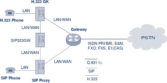
One
of the most important
interfaces in IP Telephony is between a
PBX and a voice
gateway
(VoGW).
It enables communication between
PBX phones and IP phones
(H.323 or SIP) and
can
also
facilitate communication to PSTN see
(Figure 5.1).When a PBX phone
dials a number
which
is not another PBX
extension, the PBX can
forward to the voice gateway
either calls to
numbers
beginning with a specified prefix
(so called access prefix
that the users dials
before the
required
number to get to IP Telephony network) or
all calls. Similarly, a
voice gateway can
forward
to the PBX, calls to PBX
phones.When a PBX phone
dials a number in a PSTN,
the
PBX
can forward the call directly to
the PSTN (e.g., over
ISDN) or it can forward the
call to a
voice
gateway, which forwards it to a
selected PSTN operator over
the Internet.
There
are different kinds of PBX to
voice gateway interfaces
with different features and
costs.
Your
choice of the interface-type
will probably depend on
which features you require:
acceptable
cost,
availability and whether there is
already some interface
present in the PBX and
the voice
gateway.
In this section, some
technical details are
provided on different kinds of
PBX-to-voice
gateway
interfaces. Signalling systems
are also described briefly,
such as Channel
Associated
Signalling
(CAS), E&M signalling methods, Q-signalling
and the Q.931 call
control protocol and
examples
are given of exchanged
messages during correct
communication.
-/
5.1.1.1
Subscriber Loop
A
subscriber loop, also called a
U-interface, is a 2-wire interface
used primarily when
connecting
a
telephone set to a Subscriber Line
Module Analogue (SLMA). SLMA
is the name of the
P.135
[IP
Telephony Cookbook] /
Setting Up Advanced
Services
analogue
module in a PBX. A corresponding module in a
voice gateway is called a
Foreign
Exchange
Station (FXS).
Figure
5.1 Voice gateway interfaces -
PBX role
FXS
and SLMA modules can
also be interconnected to trunk
modules.Trunk Module Analogue
(TMA)
is the name of the trunk
module on the PBX side, and
Foreign Exchange Office
(FXO) is
the
common name of the
corresponding module in a voice
gateway.
A
subscriber loop can be used
in any of the following
configurations:
-
Telephone to SLMA or
FXS;
-
FXS to TMA;
-
FXO to SLMA.
There
are two operating
modes:
-
FXO/TMA - telephone emulation (as common
terminal equipment).This is a very
simple
mode.
It only detects a ringing
signal and provides digit
dialling and switching
between off-
hook
(to close the loop) an on-hook (to
open the loop);
-
FXS/SLMA - subscriber line
circuit emulation. In this mode,
the SLMA or FXS waits
for a
closed
loop that will generate a
current flow and a signalling
tone of 425 Hz (with
10%
tolerance).The
Subscriber Line Interface Circuit
Emulation (SLIC) provides
the functions of
BORSHT
(Battery, Overvoltage, Ringing,
Supervision, Hybrid 2/4 wires
and Testing).
The
two most common methods
for end-loop signalling are loop-start
and ground-start
signalling.
DTMF (Dual Tone Multi-Frequency) is
commonly used to transmit telephone
number
digits.
DTMF tones identify numbers
0 through 9 and the * and #
symbols. Digits are
represented
by
a particular combination of two
frequencies from the high
group and the low
group. Each
group
includes only four
frequencies. Out of sixteen
possible combinations, twelve are used
on
the
keypad. DDI (Direct Dialling
In) is possible only through a
DTMF suffix, that is,
during the
connection
time when the calling party
normally is already paying
for the connection.
P.136
[IP
Telephony Cookbook] /
Setting Up Advanced
Services
-/
5.1.1.2
E&M interfaces
E&M
is commonly explained as both `Ear
and Mouth' and `recEive
and transMit'. E&M
interfaces
allow
DDI without restrictions before
the conversation starts.There
are several different types
of
E&M
interfaces according to signalling
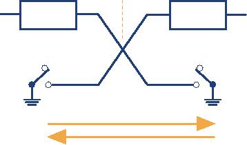
and number of interconnecting wires.Type V (see
Figure
5.2)
is very popular in Europe. In
the commonly used 6-wire
interconnection, the individual
wires
are used as follows:
-
one pair of wires (wires E
and M) is used for
signalling;
-
one pair of wires is used
for the outgoing voice
path;
-
one pair of wires is used
for the incoming voice
path.
This
6-wire connection can be reduced
into 4-wires:
-
one pair of wires (wires E
and M) is used for
signalling;
-
one pair of wires is used
for the voice path in both
directions (which can cause
a problem with
echo
cancellation and inhibits a possibility
to use an amplifier).
-48
V
-48
V
E-lead
E-lead
with
detector
with
detector
E
E
M-lead
M-lead
with
switch
with
switch
M
M
signalling
wires
outgoing
voice path
incoming
voice path
Figure
5.2 E&M signalling, type
V
Signalling
is carried out with direct current
via the E & M control wires
for call setup and
tear
down,
pulse dialling and remote
blocking. DTMF signals can
alternatively be used for
dialling.
The
E&M signalling can operate in
several modes:
-
continuous signal;
-
wink start signal;
-
delay dial;
-
immediate dial.
-/
5.1.1.3
E1/CAS trunk
CAS
(Channel Associated Signalling)
exists in many varieties
that operate over analogue
or digital
interfaces.
A common digital interface
with CAS signalling is
called E1 (European
version).The
physical
layer works in accordance with
the ITU recommendation G.703/G.704 for
PCM30/32.
The
endpoints continually send
Backward
and
Forward
marks in
16 TSLs (Timeslot of
PCM30/32,
bits ABCD) as a supervision
signal to indicate various
states of the connection.
Additionally,
the MFC-R2 (Multi Frequency
Compelled) signalling is used (in
TSL 1-15 and TSL
P.137
[IP
Telephony Cookbook] /
Setting Up Advanced
Services
17-31)
to support for several
features:
-
malicious call tracing (used to
transfer calling party
numbers);
-
override authorisation;
-
free calls;
-
called party hold.
-/
5.1.1.4
ISDN Access Interfaces
ISDN
(Integrated Service Digital
Network) is a currently preferred method of
PBX to VoGW
interconnection.
It is described in more detail and
some illustrative examples of exchange of
its
Q.931
signalling messages are
given. ISDN is a system of
digital connections allowing
the
establishment
a call with end-to-end digital
connectivity of nx64kbps. Original
recommendations
for
ISDN were in CCITT
Recommendation I.120 (1984),
which described some
initial
guidelines
for implementing ISDN.The first
commercial implementation of ISDN was in
PBX
Hicom300
(Siemens AG). Several different
signalling protocols have
emerged. It was the
1TR6
protocol
in Germany, NI (National ISDN) in
the USA and the
French National ISDN
VN3
protocol
in France.The absence of an international
standard led each European
country to make
its
own version of ISDN, which
meant incompatibility and
increased costs.Twenty-six
communication
organisations signed the
`Memorandum of Understanding on the
Implementation
of
a European ISDN' in 1992.The
signing countries were
obliged to offer a
common
technological
substructure for ISDN
network development, connecting
all of Europe. As a
result,
Q.931
signalling has been internationally
standardised.
Two
types of access methods
exist for ISDN:
-
BRI (Basic Rate
Interface);
-
PRI (Primary Rate
Interface).
BRI
delivers two 64 kb/s B
channels and one 16 kb/s D
channel.The reference configuration
of
ISDN
defined in the ITU specification
I.411 is illustrated in Figure
5.3
S
T
U
ISDN
NT2
NT1
TE1
local
exchange
Transmission
R
S
line
TE2
TA
Customer
premises
Figure
5.3 ISDN configuration
U
interface is a two-wire interface
from the telephone exchange;
it supports full-duplex
data
transfer
over a single pair of wires:
only a single device can be
connected to a U interface.
T
interface is between network terminations
NT1 and NT2: NT1 converts
two-wire U interface
into
four-wire T interface.
P.138
[IP
Telephony Cookbook] /
Setting Up Advanced
Services
S
interface and T interface
are electrically equivalent. ISDN
devices include an NT-2 in
their
design.The
NT2 communicates with terminal equipment
TE1 (ISDN terminal) or TE2
(non-
ISDN,
connected to NT2 via terminal
adapter), and handles the
layer 2 and layer 3
ISDN
protocols.
Network
Termination NT is divided into NT1 and
NT2; NT1 works in Layer 1 and NT2
in
Layers
2 and 3. NT1 and NT2 are
connected by a four-wire T
interface.
Terminal
Equipment TE1 is an ISDN compatible
device (TE1 is connected to NT2
via a four-
wire
S interface).
Terminal
Equipment TE2 is a non-ISDN-compatible
device that requires
terminal adapter
interconnection.
Terminal
Adapter provides an ISDN-compliant
interface to NT and a standard
interface to TE2
(such
as RS-232, USB, X.21,
etc.).
Because
a PBX can provide NT2 functions,
the T interface is commonly
used for interconnection
of
a PBX and a Voice Gateway.The
PBX works in the user-side
operation mode and the
Voice
Gateway
in the network-side operation
mode.
5.1.1.4.1
Q.931
The
L2 and L3 interface of ISDN is
also referred to as the
Digital Subscriber Signalling
System
No.1
(DSS1).The L2 protocol of ISDN is ITU
Q.920/Q. 921 and the L3
protocol is ITU
Q.930/Q.931.
Q.932 enables general
procedures for accessing and
controlling supplementary
services.
Q.931
provides call control
capabilities. Some of the
most important Q.931
messages are:
-
Setup;
-
Setup acknowledge;
-
Call proceeding;
-
Progress;
-
Alerting;
-
Connect;
-
Connect acknowledge;
-
Disconnect;
-
Release complete;
-
Information.
The
destination digits can be sent in
two forms during
call-setup:
-
complete called party number in
the SETUP message, also
known as the en-bloc
signal;
-
one by one in separate
messages, also known as the
overlap signal
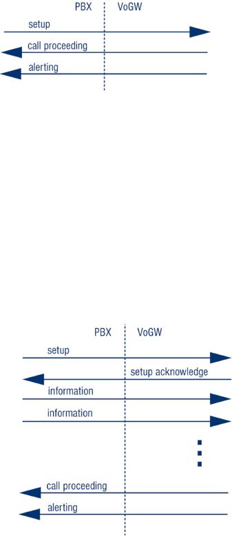
An
example of Q.931 Call
control messages in call-setup
with the en-bloc signal is
shown in
Figure
5.4.This example corresponds to the
following setup:
-
Cisco AS5300 was used as a
Voice Gateway and debugging
was enabled with `debug
isdn q931'
command;
P.139
[IP
Telephony Cookbook] /
Setting Up Advanced
Services
-
The call was initiated from
the Technical University in
Ostrava to the Czech Technical
University in
Prague,.The
PBX was connected through
ISDN/PRI and the called
number was sent as the
en-bloc
in
the SETUP message;
-
The Calling Party Number was
596991699
-
The Called Party Number was
224352979
Figure
5.4 Q.931 call control
messages in call-setup with
the en-bloc signal
Jun
24 18:30:12.817: ISDN Se0:15: RX <-
SETUP pd = 8 callref =
0x0002
Sending
Complete
Bearer
Capability i = 0x8090A3
Channel
ID i = 0xA9838E
Calling
Party Number i = 0x00, 0x83,
'596991699', Plan:Unknown,
...
Called
Party Number i = 0x80,
'224352979', Plan:Unknown,
Type:U...
High
Layer Compat i =
0x9181
Jun
24 18:30:12.837: ISDN Se0:15: TX ->
CALL_PROC pd = 8 callref =
0x8002
Channel
ID i = 0xA9838E
Jun
24 18:30:13.129: ISDN Se0:15: TX ->
ALERTING pd = 8 callref =
0x8002
Progress
Ind i = 0x8188 - In-band
info or appropriate now
available
Progress
Ind i = 0x8182 - Destination
address is non-ISDN
An
example of Q.931 call
control messages in call-setup
with the overlap signal is
shown in Figure 5.5.
Figure
5.5 Q.931 call control
messages in call-setup with
overlap
P.140
[IP
Telephony Cookbook] /
Setting Up Advanced
Services
This
example corresponds to the
following setup:
-
Cisco AS5300 was used as a
Voice Gateway; debugging was
enabled with a debug
isdn q931
command;
-
The call was initiated from
the Czech Technical University in
Prague to PSTN (Public Switched
Telephone
Network); the PBX in Prague
was connected through ISDN/PRI
and the called number
was
sent
as the digit by digit
(overlap) in the SETUP
and
INFOMATION
messages;
-
The Calling Party Number is
224355406;
-
The Called Party Number is
224324997.
Jun
24 18:31:43.092: ISDN Se1:15: RX <-
SETUP pd = 8 callref =
0x540A
Bearer
Capability i = 0x8090A3
Channel
ID i = 0xA1838E
Progress
Ind i = 0x8183 - Origination
address is non-ISDN
Calling
Party Number i = 0x31, 0x81,
'224355406', Plan:ISDN,
Type:.
Called
Party Number i = 0x81, '2',
Plan:ISDN, Type:Unknown
Jun
24 18:31:43.104: ISDN Se1:15: TX ->
SETUP_ACK pd = 8 callref =
0xD40A
Channel
ID i = 0xA9838E
Jun
24 18:31:43.808: ISDN Se1:15: RX <-
INFORMATION pd = 8 callref =
0x540A
Called
Party Number i = 0x81, '2',
Plan:ISDN, Type:Unknown
Jun
24 18:31:45.152: ISDN Se1:15: RX <-
INFORMATION pd = 8 callref =
0x540A
Called
Party Number i = 0x81, '4',
Plan:ISDN, Type:Unknown
Jun
24 18:31:46.536: ISDN Se1:15: RX <-
INFORMATION pd = 8 callref =
0x540A
Called
Party Number i = 0x81, '3',
Plan:ISDN, Type:Unknown
Jun
24 18:31:47.564: ISDN Se1:15: RX <-
INFORMATION pd = 8 callref =
0x540A
Called
Party Number i = 0x81, '2',
Plan:ISDN, Type:Unknown
Jun
24 18:31:48.896: ISDN Se1:15: RX <-
INFORMATION pd = 8 callref =
0x540A
Called
Party Number i = 0x81, '4',
Plan:ISDN, Type:Unknown
Jun
24 18:31:51.012: ISDN Se1:15: RX <-
INFORMATION pd = 8 callref =
0x540A
Called
Party Number i = 0x81, '9',
Plan:ISDN, Type:Unknown
Jun
24 18:31:52.696: ISDN Se1:15: RX <-
INFORMATION pd = 8 callref =
0x540A
Called
Party Number i = 0x81, '9',
Plan:ISDN, Type:Unknown
Jun
24 18:31:54.480: ISDN Se1:15: RX <-
INFORMATION pd = 8 callref =
0x540A
Called
Party Number i = 0x81, '7',
Plan:ISDN, Type:Unknown
Jun
24 18:31:54.604: ISDN Se1:15: TX ->
CALL_PROC pd = 8 callref =
0xD40A
Jun
24 18:31:55.684: ISDN Se1:15: TX ->
ALERTING pd = 8 callref =
0xD40A
Progress
Ind i = 0x8288 - In-band
info or appropriate now
available
-/
5.1.2
Gatewaying from H.323 to PSTN/ISDN
One
of the most useful H.323
services is the ability of
VoIP calling parties (H.323
world) to reach
the
PSTN (classic telephony
world).This service is provided by
H.323/PSTN gateways and
the
functionality
they provide is:
-
forwarding of incoming calls from
the PSTN and call
signalling to H.323;
-
termination of incoming calls
from H.323 and forwarding to
the PSTN;
-
accounting for calls
utilising the
gateway;
-
optional support for H.320 (ISDN)-capable
conferencing endpoints.
P.141
[IP
Telephony Cookbook] /
Setting Up Advanced
Services
This
section introduces the basic
principles on how to perform gatewaying
using H.323. Basic
configuration
guidelines and operational principles of
commercial and open source
gatekeepers
are
described here in order to
detail how to set up
gatekeepers for interconnection with
PSTN.
Moreover,
details on the configuration of gateways
are given in order to
provide guidelines on
how
to configure gateways to be part of an
H.323 network.
-/
5.1.2.1
Using a RADVISION OnLAN 323
L2W-323 Gateway
The
RADVISION OnLAN 323 L2W-323
Gateway is a hardware-based H.323 to
H.320 gateway,
which
allows H.323 endpoints to
reach destinations on the
PSTN or specialised H.320
(ISDN-
based)
endpoints and vice versa.The L2W-323, in
its most common configuration, has
four
Ethernet
(LAN) interfaces and two
ISDN BRI (WAN) interfaces. It is
designed for
stand-alone
use
and thus integrates the
functions of a gatekeeper, as well as a
gateway, under the same
hood. It
is
presently not available for
sale but it has quite a large installed
base, considering that the
Cisco
3520
is essentially the same
product marketed by
Cisco.
5.1.2.1.1
Installation
Its
installation is straight-forward, requiring merely
power, a network interface, BRI
ISDN
interfaces
and a PC on the same LAN for
setting-up initial configuration
parameters through a
windows-based
application.To manage the device,
install the RADVISION OnLAN
Tools from
the
installation disks, by running
the setup.exe
program
on the PC. Since the
gateway has no
network
configuration to begin with, the PC
running the software will
have to be on the
same
LAN
in order to perform initial
network setup of the unit.
After specifying an IP address
for the
Ethernet
interface of the unit, the
configuration application can then be
run remotely.
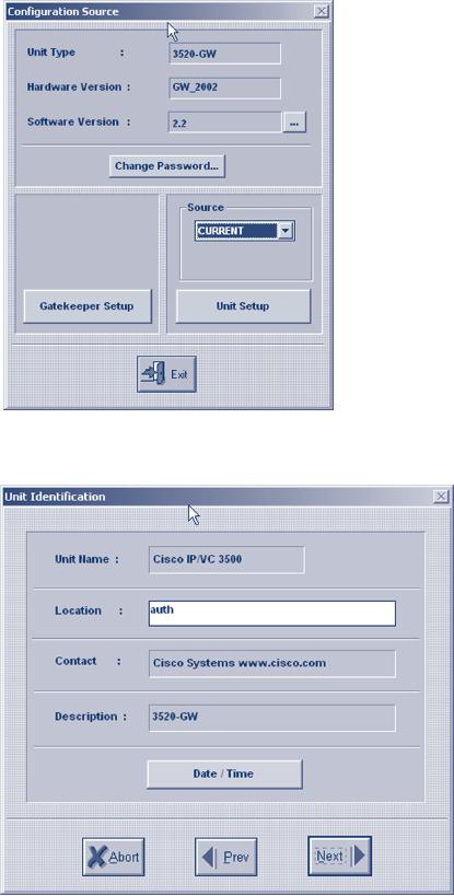
5.1.2.1.2
Configuration
When
running the configuration application,
you will need to specify
the IP address of the
target
device,
or choose one from the list
of detected devices on the
same LAN. After entering
the
administrative
password, you are presented
with a window where you
specify which configuration
to
edit.The options are to edit
the currently-loaded configuration of the
device, or a previously
saved-to-file
configuration.The next step is to select
which functionality to configure:
the
gatekeeper
(select Gatekeeper
Setup) or the
gateway (select Unit
Setup).
Only
the second option is of
interest, since the gateway
can register with any of
the gatekeepers
detailed
above, and the built-in
gatekeeper can be turned off
since it provides only
basic
functionality.
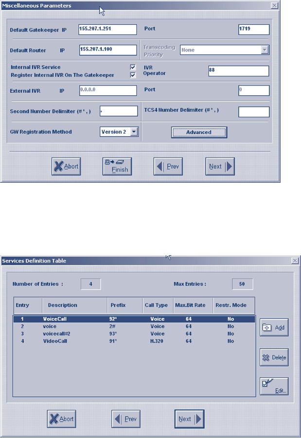
Select Unit
Setup and
proceed with Unit
Identification and
Date/Time
options,
which are informational only, by
pressing the Next
button.
The
next screen, Miscellaneous
Parameters,
presents a number of configuration options.The
critical
settings are the ones
for Default
Gatekeeper and
for Default
Router IP, which
you
must
set to the IP address of the
gatekeeper controlling your zone,
and the IP address of
the
router
(network gateway in the IP protocol
sense).The rest of the
settings can be left at
their
default
state.
P.142
[IP
Telephony Cookbook] /
Setting Up Advanced
Services
Figure
5.6 OnLAN configuration entry
Figure
5.7 OnLAN unit
identification
The
next screen, LAN
Port Settings, is
responsible for configuring the Ethernet
interfaces.There
are
four screens, one for each of
the four Ethernet ports.
Configuring just one
interface with an IP
Address
and
IP
Mask is
sufficient. A summary screen
with settings for all four
ports follows.
P.143
[IP
Telephony Cookbook] /
Setting Up Advanced
Services
Figure
5.8 OnLAN miscellaneous
parameters and gateway
registration on gatekeeper
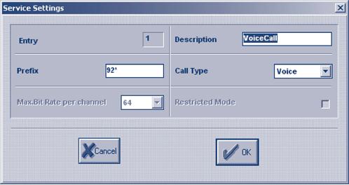
The
next screen, Services
Definition Table, is the
most important one, since it
defines the
services
that the gateway will
make available to calling
parties, by registering them with
its
controlling
gatekeeper.
Figure
5.9 OnLAN-defined gateway
services
P.144
[IP
Telephony Cookbook] /
Setting Up Advanced
Services
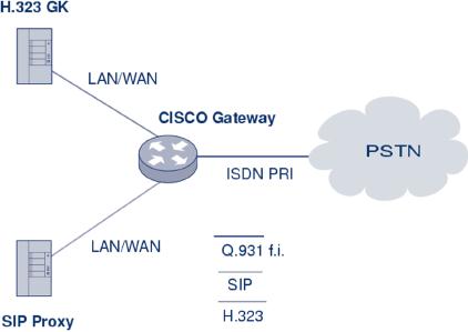
Each
service definition includes
information about the
Prefix. It is
called with the Call
Type,
which
can be voice-only or H.320
(voice and video), and the
Maximum
Bit Rate which a
call
of
this type and will be
required. By defining different services,
the calling parties are
given the
option
to choose the type of call
they can make, based on
the service prefix they
dial, assuming
the
prefixes are well known to
the users, or at least that
the gatekeepers have
pre-selected default
gateway
services. For example, if
the gateway defines a
voice-only service with a
prefix of e.g., 9,
the
administrator of the gatekeeper
will likely make this
the default service to route
all calls to the
gateway.
Any user requiring a voice
and video call will have to
know the service prefix,
e.g., 8, for
that
special type of call.The L2W
gateway will already have
template services defined, but
you can
add,
edit or delete services as needed.There
is certainly one thing you
will need to customise
and
that
is the service prefixes, in
order to make them match
your local dialling
scheme.
Figure
5.10 OnLAN editing of a service
definition
The
next screens refer to
WAN
Port Settings which,
for an ISDN interface,
present relative
settings.The
country-specific ISDN protocol must be
selected, and the Phone
Number
connected
to the ISDN port can be
indicated. Also, specific
services can be enabled or
disabled
for
this WAN port, assuming more
than one type of WAN port is
available, each with
distinct
capabilities.
A summary screen with
settings for all WAN ports
follows.
At
the end of the configuration
wizard, you are given
the option to save the
new configuration
settings
in a file before downloading them to
the gateway itself. At this
point, the gateway is
reloaded
and the new settings
are applied.
5.1.2.1.3
Operation
Immediately
after configuration and reload,
the gateway attempts to
register its services with
the
gatekeeper.This
must be verified on the gatekeeper-side
before attempting to use the
gateway's
services.
Specifically, there are two
things that must be checked:
a) the registration of the
gateway
on
the gatekeeper and b) the
registration of its service
prefixes on the gatekeeper.
For example, on
the
Cisco MCM Gatekeeper, the
appropriate commands would
be:
>
show gatekeeper
endpoints
GATEKEEPER
ENDPOINT REGISTRATION
================================
CallSignalAddr
Port RASSignalAddr
Port
Zone Name
Type
Flags
P.145
[IP
Telephony Cookbook] /
Setting Up Advanced
Services
194.257.8.150
1820
194.257.8.150
1024
gk.mydomain.org
CH320-GW
H323-ID:
GW4134522623
At
least one entry should refer
to the registration of the
gateway, indicating its IP address,
the type of
registration
(H320-GW) and the H.323
alias of the unit
(GW4134522623).
>
show gatekeeper
gw-type-prefixes
GATEWAY
TYPE PREFIX TABLE
=========================
Prefix:
92*
Zone
gk.mydomain.org master gateway
list:
194.257.8.150:1820
GW4134522623
Prefix:
93*
Zone
gk.mydomain.org master gateway
list:
194.257.8.150:1820
GW4134522623
A
listing of all registered services at
the gatekeeper should include an entry
for each of the
services
defined
on the gateway, indicating the
prefix, and the IP address
and the H.323 alias of
the gateway
to
forward calls to. If registration of
services with the gatekeeper
is confirmed, the gateway is
ready
to
service calls, which can be
traced through the gatekeeper
tools.
The
gateway can be monitored by a
command-line interface
only:
>
telnet 194.257.8.150
Trying
194.257.8.150...
Connected
to 194.257.8.150.
Escape
character is '^]'.
VxWorks
login: admin
Password:
->
At
this prompt, no command can be
entered to explicit logs, but
passive monitoring of events
is
provided.
Logs on this interface can
be overwhelming, but the L2W
gateway does not provide
any
other
means of debugging, or monitoring.
Please note that in the
current release a bug makes
the
L2W
gateway unregister from the
gatekeeper after some time,
making its services
unavailable
to
the zone. Check often for
registration of gateway services
and in case they are
lost, reboot the
gateway
to force gatekeeper registration
again.The most flexible way
to reboot the gateway is
to
use
the telnet interface, login,
and apply a Control-X
command.
5.1.2.1.4
Authentication
In
environments where gatekeeper
registration is authenticated, the
gateway has to provide
authentication
credentials in order for the
gatekeeper to allow its
registration. If H.235
authentication
is required by the gatekeeper,
the L2W gateway does
not support it and
administrative
measures must be taken at
the gatekeeper-side to exempt it from
authentication. If
authentication
by H.323 alias and password
is required, e.g., for the
Cisco MCM piggy-back
mechanism,
the L2W gateway has a fixed
H.323 alias that it tries to
register with the
gatekeeper
P.146
[IP
Telephony Cookbook] /
Setting Up Advanced
Services
(of
the format GWnnnnnnnnnn, where n is a
number generated by the gateway
itself and is not
configurable).The
administrator must make sure
that this specific H.323
alias is allowed to
register
on
the gatekeeper with no
password. Similar measures
must be taken in case an
IP-address plus
H.323
alias-authentication method is applied on
the gatekeeper-side.
-/
5.1.2.2
Gatewaying H.323 using
Cisco
In
this subsection, an example of
how a Cisco Voice Gateway
should be configured
for
interconnection
with a PBX is presented. See
Figure 5.11 for an illustration of
the
interconnection.The
same procedure could be used
for interconnecting a Cisco Voice
Gateway
with
PSTN/ISDN
Figure
5.11 Cisco voice gateway
interconnection
Gateway
configuration can be divided into three
main parts:
-
Protocol configuration;
-
Interface configuration;
-
Dial-peer configuration.
The
example corresponds to the
following setup. As a Voice Gateway is
used, Cisco 2651XM
with
appropriate
IOS is connected through PRI/ISDN to
the PBX and is registered to
a gatekeeper.
Examples
of the configuration were cut off
from the Cisco CLI command
and show running-
config
output and
comments.
5.1.2.2.1
Protocol configuration
Gatekeeper
peering and gateway id are
set up in this section. The
Cisco gateway could serve as
a
voice gateway for both
H.323 and SIP protocols at
the same time, but the
SIP protocol-specific
part
is configured in a completely different configuration
section of the gateway (not
the
sip-gateway,
see Section 5.2.2). Use of
the h323-gateway
command is
recommended, set in a
loopback
interface configuration section. Use of a
loopback IP address in registration
and
P.147
[IP
Telephony Cookbook] /
Setting Up Advanced
Services
accounting
messages helps to manage the
system easily if the gateway
has more than one
interface
used for VoIP.
h323-gateway
voip
interface
h323-gateway
voip
id
GK1-CESNET2 ipaddr 195.113.113.131
1718 priority 100
h323-gateway
voip
id
GK2-CESNET2 ipaddr 195.113.144.85
1718
h323-gateway
voip
h323-id
VoGW-ZCU
h323-gateway
voip
tech-prefix
1#
Voice
gateway is registered to gatekeeper
GK1-CESNET2
A
second gatekeeper GK2-CESNET2 is
used as backup
The
h323-id of the Voice Gateway is VoGW-ZCU.
It is checked on the gatekeeper
and is needed
for
successful registration
5.1.2.2.2
Interface configuration
Interconnection
to a PBX or a PSTN also has to be
properly set up at interface
level
(router(config-if)#).Telephony
interface configuration is independent on
the used VoIP
signalling
protocol. In this section, there
are configured ISDN
parameters for signalling
the
channel
(the sixteenth channel has number 15 by
Cisco).
interface
Serial0/0:15
isdn
switch-type primary-net5
isdn
overlap-receiving T302
5000
isdn
protocol-emulate network
isdn
send-alerting
isdn
sending-complete
isdn
outgoing-voice info-transfer-capability
3.1kHz-audio
primary-net5
is the
setting of the DSS1
(EuroISDN) signalling protocol on the
primary
interface
PRI (basic-net3 is used on
the BRI).
timer
T302 is the
interval in milliseconds for overlap
mode (the interface waits 5
seconds for
possible
additional call-control
information).
isdn
protocol-emulate network is the
configuration of the Layer2 and
Layer3 of the ISDN
protocol,
the Voice Gateway is working as NT
and the PBX is in the
slave mode.
isdn
send-alerting causes
the Alerting
message
to be is sent out before the
Connect
message.
isdn
sending-complete is an optional
enhancement, where the sending
complete
information
element is required in the outgoing
call
setup message.The
last command specifies
the
transfer capability for
voice calls.
5.1.2.2.3
Dial-peer configuration
The
next configuration step is setting up
the call rules.This is done
by a dial-peer
command
set
from
the basic config mode
(router(config)#) of the
Cisco gateway. If the
gateway should
provide
calls from both sides (to
and from the PSTN/PBX), a
set of at least two
dial-peers has to
be
configured.
P.148
[IP
Telephony Cookbook] /
Setting Up Advanced
Services
dial-peer
voice 1 pots
destination-pattern
42037763....
progress_ind
alert enable 8
direct-inward-dial
port
0/0:15
These
commands specify rules for
calls to the PSTN(PBX) from
the VoIP-side.
The
called
number prefix is
42037763 and must be
followed with four digits of
extension (four
dots
substitution pattern).The best
match to destination pattern
chooses the right dial
peer.
progress_ind
alert enable 8 is the
transcription of the Progress
element
in the Alerting
message.This
transcription causes B-channels to interconnect
and allows the resolving of
a
possible
problem with the ring-back
tone.
The
rules are written into
the port interface 0/0:15
with
DDI
(Direct
Dialling In).
dial-peer
voice 112 voip
destination-pattern
420.........
session
target ras
no
vad
These
commands specify rules for
calls leading to the
VoIP-side from the
PSTN(PBX):
-
The called number prefix is 420
and it must be followed with
nine digits;
-
The target of this session is
the gatekeeper, accessible through
RAS signalling;
-
The last command specifies that
the Voice Activity Detection is
not possible (higher
voice
quality);
-
The default configuration is VAD with CNG
function (Comfort Noise
Generation).
The
user is reminded here that
the listed configuration may
not be sufficient to run a
voice gate-
way
on Cisco routers. Commands
may depend on the type of
the router and the
IOS version used.
-/
5.1.2.3
Gatewaying H.323 using a GNU
Gatekeeper
How
to set up services using GNU
Gatekeeper was already
described in Section 4.5.3.
Here,
enhanced
configuration and operation for
GnuGK to be used with a
gateway in order to
reach
people
who are using ordinary
telephones is described.
The
gatekeeper has to know which
calls are supposed to be
routed over the gateway
and what
numbers
shall be called directly. Using
the [RasSrv::GWPrefixes] section
of the config
file,
the
administrator
tells the gatekeeper the
prefix of numbers that will
be routed over the
gateway.
[RasSrv::GWPrefixes]
gw-PSTN=0
gw-MOBILE=3
These
entries tell the gatekeeper
to route all calls to E.164
numbers, starting with 0, to
the
gateway
that has registered with the
H.323 alias gw-PSTN, and
all calls to the E.164
numbers,
P.149
[IP
Telephony Cookbook] /
Setting Up Advanced
Services
starting
with 3, to the gateway that
has registered with the
H.323 alias gw-MOBILE. If
there is
no
registered gateway with
these alias', the call
will fail. Note that
you must use the
gateway alias.
You
cannot just tell the
gatekeeper the IP number of the
gateway. Static configuration of
gateway-ip-address/prefix
is, in
principle, possible using the
[RasSrv::PermanentEndpoints]
configuration
section, but such a solution is not
advised, because it leads to
errors when a network
reconfiguration
is done.
When
using a gateway, you often
have to use different numbers
internally and rewrite
them
before
sending them over a gateway
into the telephone
network.You can use
the
RasSrv::RewriteE164
section
to configure this.
[RasSrv::RewriteE164]
12345=08765
In
this example, the gatekeeper
is configured to replace the
numbers 12345 at the beginning
of
the
E.164 number dialled to 08765 (for
example, 12345-99 is rewritten to
08765-99). Please
refer
to
rewrite
for
the section syntax.
A
gateway can register its
prefixes with the gatekeeper
by containing supportedPrefixes
in
the
terminalType
field of
RRQ.The following option
defines whether to accept
the specified
prefixes
of a gateway.
AcceptGatewayPrefixes=1
#Default:
1
5.1.3.Â
Gatewaying from SIP to
PSTN/ISDN
-/
5.1.3.1
Gatewaying SIP using
Cisco
Configuration
of a SIP gateway is almost
same as the configuration of an H.323
Gateway and
because
configuration of an H.323 Gateway is
already described in Section
5.1.2.2, the same
settings
are not described again
here (for an interface configuration
which is exactly the
same).
Only
configuration specific to SIP is
described. Readers should
read Section 5.1.2.2
first.
Dial-peer
configuration is
almost same as described in
Section 5.1.2.2.The only difference
is
that
ras is replaced by sip-server.
For
example,
dial-peer
voice 112 voip
destination-pattern
420.........
session
target sip-server
no
vad
P.150
[IP
Telephony Cookbook] /
Setting Up Advanced
Services
-/
5.1.3.2
sip-ua configuration
All
the SIP parameters are
configured in the sip-ua
section.
An example configuration might
look
like:
sip-ua
nat
symmetric role
passive
nat
symmetric check-media-src
retry
invite 4
retry
response 3
retry
bye 2
retry
cancel 2
sip-server
dns:iptel.org
The
first parameters configure the
gateway to be passive.That is good
for the Connection
Oriented
Media.Value.
Passive means that if there
is a direction=active
parameter
in SDP, then
the
gateway will wait with
the sending of media until
it receives the first media
packet from the
remote
party.This feature can be very
useful for NAT traversal. It
can be enabled only when
the
gateway
is in the public
Internet.
The
second line configures the
gateway to check for the
source of incoming media and
send its
media
there if it is in a symmetric mode.This
option is related to the
previous one.
Retry.
Parameters specify how many
times various SIP messages
should be retried.
The
last parameter specifies how
to reach the SIP Proxy. In
this case, the gateway
will send all
the
SIP
traffic to iptel.org
and
it will use DNS to resolve
it to IP.
-/
5.1.4
Gatewaying from SIP to H.323 and vice versa
SIP
to H.323 gatewaying and vice
versa is a complex matter
since, up to now, only
basic
translations
of services are possible
using this gatewaying. A
great development effort in this
topic
is
useless since the gatewaying
makes the users loose
the native protocol, (H.323 /
SIP)
supplementary
services.These types of gateways,
even if valuable for
connecting SIP and
H.323
worlds,
are not yet widely
deployed because the
adoption of proprietary protocols
provides the
users
with more value-added services.
For the sake of
thoroughness, this section
deals with
operations,
descriptions and simple configuration of
SIP-H.323 Gateways.
A
SIP/H.323 Gateway allows
users to make an audio call
from a SIP network to an
H.323
network
and vice-versa.The entities making
the calls using such a
gateway can be:
-
a SIP user agent;
-
an H.323 terminal;
-
a SIP Proxy Server;
-
an H.323 Gatekeeper;
-
another gateway (e.g.,
SIP-PSTN).
Various
types of operations can be performed
using a SIP/H.323 Gateway
and can be basically
divided
into five categories
(detailed descriptions, follow
this section):
-
a user registration;
-
a call from SIP to
H.323;
P.151
[IP
Telephony Cookbook] /
Setting Up Advanced
Services
-
a call from H.323 to
SIP;
-
media-switching and
capabilities-negotiation;
-
a call termination.
There
are different modes in which a
SIP/H.323 Gateway can
operate. In this section,
basic
operation
modes are described. For
more detailed operations, please
refer to `Interworking
Between
SIP/SDP and H.323' for
examples of basic functionalities as well
as configuration
guidelines.
Actual configurations are relative to
specific hardware/software and
are out of the
scope
of this document.
A
SIP/H.323 Gateway may have a
built-in H.323 Gatekeeper or a
built-in SIP registrar
(optional
presence
or activation of such entities
are dependent on software
implementation choices).
Different
operations are performed by the
SIP/H.323 Gatekeeper depending on
whether the
internal
gatekeeper/internal SIP register is
activated or not.
If
a SIP/H.323 Gateway is configured
appropriately, it should try to
register both with an
H.323
Gatekeeper
using RAS procedures and
with a SIP registrar, in
order to perform the
gateway's
address
resolution from either side.
A SIP entity can query
the registrar, whereas an
H.323 entity
can
query the H.323 Gatekeeper
to locate the SIP/H.323
Gateway. If the internal gatekeeper
is
activated,
then no registration to an external
gatekeeper should be performed. If the
internal SIP
registrar
is activated, then no registration to an
external SIP registrar should be
performed. At least
one
H.323 Gatekeeper and at
least one SIP registrar
should be always specified/activated
for
operations
to be successful.
If
an H.323 Gatekeeper is not
specified, then a broadcast
GRQ, Gatekeeper
ReQuest,
message
should
be sent to discover it. Once
the H.323 Gatekeeper address
is known, an RRQ,
Registration
ReQuest, message
is used to register to it.The
SIP/H.323 Gateway alias
should be
inserted
in such a message. If no built-in
SIP registrar is used, then
an external SIP registrar
address
should always be specified (a
SIP
REGISTER message
should always contain
the
destination
address).The contact address
inserted in the REGISTER
message
should be that of
the
SIP/H.323 Gateway itself.
-/
5.1.4.1
User registration
In
this section, details are
given on different architectures for
user registration/address
resolution.
User
registration servers are SIP
registrars and H.323
Gatekeepers. If a SIP/H.323 Gateway
has
direct
access (either built-in or
configured) to user registration
servers, this simplifies locating
users
independently of the signalling
protocol.The user registration
server forwards the
registration
information from one
network, to which it belongs, to
the other.
Depending
on the internal architecture of the
SIP / H.323 Gateway, we can
distinguish three
different
cases:
1.
The
SIP/H.323 Gateway contains a
SIP Proxy and registrar
(Figure 5.12).The H.323
Gatekeeper
maintains the registration
information and thus H.323
users register via the
usual
procedure.
On the other hand, when a
SIP
REGISTER request
is received by the SIP
registrar
server,
it generates a registration request
(RRQ) to the H.323
Gatekeeper. The RRQ contains
the
translation of a SIP
URI into
the H.323 Alias
Address;
P.152
[IP
Telephony Cookbook] /
Setting Up Advanced
Services
SIP/H.323
Gateway
H.323
SIP
UsTE1 gent
er
A
Gatekeeper
SIP
proxy
/registar
REGISTER
RRQ
RRQ
H.323
Terminal
Sip
messages
RRQ
= Registration ReQuest
H.323
messages
Figure
5.12 A SIP/H.323 Gateway containing a
SIP Proxy and
registrar
2.
The
SIP/H.323 Gateway contains an
H.323 Gatekeeper (Figure 5.13).The
user registration
information
from both networks is maintained by the
SIP Proxy Server.The SIP
registrar receives
the
forwarding of any H.323 registration
request received by the
H.323 Gatekeeper.The
SIP
server
stores the user registration
information of both the SIP
and H.323 entities;
SIP/H.323
Gateway
H.323
SIP
SIP
UsTE1 gent
er
A
Gatekeeper
proxy
/registar
REGISTER
REGISTAR
RRQ
Sip
messages
RRQ
= Registration ReQuest
H.323
Terminal
H.323
messages
Figure
5.13 A SIP/H.323 Gateway containing an
H.323 Gatekeeper
3.
The
SIP/H.323 Gateway is independent of a
proxy or a gatekeeper (Figure
5.14). User
registration
is done independently in the
SIP and H.323
networks.
OPTIONS
H.323
SIP/H.323
SIP
UsTE1 gent
er
A
Gatekeeper
Gateway
LPQ
SIP
proxy
/registar
REGISTER
RRQ
RRQ
= Registration ReQuest
Sip
messages
LRQ
= Location ReQuest
H.323
Terminal
H.323
messages
Figure
5.14 SIP/H.323 Gateway
Independent
P.153
[IP
Telephony Cookbook] /
Setting Up Advanced
Services
-/
5.1.4.2
Call from SIP to
H.323
The
SIP/H.323 Gateway operations
are described only when it
acts as an active
intervention.
Since,
when the SIP/H.323 Gateway
contains a SIP Proxy and
registrar, the SIP
registration
information
is also available through the
H.323 Gatekeeper and any
H.323 entity can resolve
the
address
of SIP entities reachable
via the SIP server.Thus, an
active intervention is performed
only
in
the case of calls
originating from the SIP
domain towards the H.323
one.
In
such a case, if a SIP user
agent wants to talk to another
user located in the H.323
network, it
sends
a SIP
INVITE message
to the SIP server, which, in
turn, forwards an H.323
location
request
(LRQ) to the configured
gatekeeper. If no gatekeeper was
configured, then a
broadcast
LRQ
is sent.The gatekeeper responds
with the IP address of the
H.323 user, making the
SIP
server
able to route the call to
the destination. Drawbacks of
this approach are that
the H.323
Gatekeeper
may be highly loaded because
of all the registrations in
the SIP network.
Of
course, when the SIP/H.323
Gateway is independent of proxy or
gatekeeper, it must
query
the
other network for user
location, acting an active intervention
in the call.
-/
5.1.4.3
Call from H.323 to
SIP
Similar
to the previous case, calls
from the H.323 domain to the
SIP one only require an
active
intervention
of the SIP/H.323 Gateway
when the originating domain
contains an H.323
Gatekeeper.
Such a consideration applies
since H.323 terminals appear
to the SIP user agents
as
SIP
URLs within the same domain
(for further information on how H.323
addresses are
translated
to SIP URLs, please refer to
`Inter-working between SIP/SDP
and H.323').
In
this case, if an H.323 user
wants to talk to a user located in
the SIP network, it sends
an
admission
request (ARQ) to its
gatekeeper.The gatekeeper has to send
the location request
(LRQ) to all
the gatekeepers it has configured as
neighbours. If the SIP/H.323
built-in
gatekeeper
receives the LRQ, it tries
to resolve the address of a
SIP user.This address
resolving is
done
by sending a SIP
OPTIONS request.
If this operation succeeds
and the user is
currently
available
to be called, the SIP/H.323
Gateway replies to the H.323
network gatekeeper with
the
location
confirmation (LCF), after the
H.323 terminal knows that
the destination is
reachable.
Drawbacks
of this approach are, as in
the previous case, that
the SIP Proxy has to store
all H.323
registration
information.
Of
course, when the SIP/H.323
Gateway is independent of proxy or
gatekeeper, it must
query
the
other network for user
location, making an active intervention in
the call.
-/
5.1.4.4
Media switching and
capability negotiation
A
SIP/H.323 Gateway should be
configured in order to have
media transport directly
connected
between
the SIP and the
H.323 entities.When, in some cases,
this is not possible, the
SIP/H.323
Gateway
should have a built-in media
switching fabric activated to forward RTP
and RTCP
packets
from one client to the
other. A great inter-working effort is
carried out in
P.154
[IP
Telephony Cookbook] /
Setting Up Advanced
Services
capabilities-negotiation.While
SIP offers media with
the INVITE
message,
the normal H.323
mode
is to open a separate H.245
channel. In this case, the
SIP/H.323 Gateway has to start
a
muted
SIP call, and re-negotiate
the capabilities later,
unless the H.323 client
supports the use of
the
FastStart procedure. If both of these
conditions can not be ensured,
the gateway must use
the
default
codecs for both sides and,
eventually, perform media
transcoding.
-/
5.1.4.5
Call termination
Since
a call can be terminated from both
H.323 and SIP clients,
appropriate message
translation/forwarding
is required from the
SIP/H.323 Gateway: a SIP
BYE
message
is mapped
to
an H.323 Release
Complete message
and vice-versa.
-/
5.1.4.6
Configuration guidelines
In
this section, basic configuration
principles are given, abstracting
them from specific software
in
order
to give general guidelines
and give information rapidly becoming
out-of-date. Apart from
low-impact
configuration information (log files
location, log level setting), in
order to configure a
SIP/H.323
Gateway, it is likely that
there will be a need to
configure:
-
enabling/not enabling of built-in
SIP Proxy/registrar and related
configuration. Please refer to
the
section on setting up SIP
services for information on
how to configure a
SIP
Proxy/registrar
server;
-
the remote address/port of
the H.323 network gatekeeper
(either if SIP built-in
proxy/
registrar
is enabled and no broadcast
requests have to be sent, or if
the SIP/H.323 Gateway
is
independent
of proxy or gatekeeper);
-
enabling/not enabling of a built-in
H.323 Gatekeeper and related
configuration. Please refer to
section
on setting up H.323 services
for information on how to
configure an H.323
Gatekeeper;
-
the remote address/port of
the SIP network proxy/registrar
(either if H.323 built-in
gatekeeper
is
enabled, or if the SIP/H.323
Gateway is independent of proxy or
gatekeeper).
-/
5.1.5
Accounting Gateways
Accounting
may be performed both on gatekeepers and
on gateways. Even if, in
principle,
accounting
done on gateways is possible,
the best solution is to centralise
the accounting on
gatekeepers,
which are able to maintain
all the call information
(if configured in call
signalling
routed
mode). Information on how to
perform accounting may be found in
Section 4.3.
-/
5.2
Supplementary services
This
section deals with
supplementary services both using
H.323 and using
SIP.These
supplementary
services are intended to be
used in addition to the basic
ones, but still in a
telephony-like
environment.The supplementary services
are protocol-specific and are
intended to
P.155
[IP
Telephony Cookbook] /
Setting Up Advanced
Services
replicate
all the wide range of
services we are already used
to in the PSTN networks.
Section
5.2.1
will deal with the
supplementary services using
the H.323 protocol, while
Section 5.2.2 will
deal
with supplementary services
using the SIP
protocol.
-/
5.2.1
Supplementary services using H.323
This
section describes the
supplementary services of the
H.323 protocol as specified in
the
H.450.x
supplementary services
recommendations.
The
supplementary services of H.323
are defined in the H.450
series, which establishes
the
signalling
between endpoints necessary to
implement the telephone-like services.
Although some
of
these services have the
same functionalities as the equivalent
ones developed for the
circuit-
switched
networks, it is relevant to note that
the paradigm of H.323 is completely
different.
The
peculiar characteristic of the
supplementary services of H.323 is
that the protocol
actions
needed
for their control are
performed using peer-to-peer signalling.
In other words, the
protocols
are designed in such a
manner that functional entities
communicate with their
peer
entities
(clients, gatekeepers, gateways
etc.) directly without requiring network
intervention.
The
services are distributed in the
endpoints, based on the suitability of
the service at that
endpoint.
For example, an H.323 client
maintaining the state of the
calls is suitable for
the
implementation
of services such as call
transfer, call forwarding, call
waiting, and so on. Since
a
peer-to-peer
model is used by the supplementary
services of H.323, the
payload and the
signalling
of the services are
transparently sent through the
network without requiring
the
processing
of any network
element.
Considering
also that the state of
the calls is distributed to the
endpoints involved in the calls,
it
can
be deduced that services for
H.323 can be deployed by any
manufacturer and sold directly
to
the
end-user for deployment.This feature of
the service deployment leads
to a low cost entry
for
the
service provider and a
service cost for customer
characterised by an initial cost
for the
software
implementing the service for
unlimited use.This last
aspect implies that new
services can
be
distributed to VoIP users in the
same way as any other
software is sold in the
market today.
This
scenario raises problems
related to the subscription-control of
these supplementary
services.
To
this aim, the signalling
necessary for these services
should be routed through the
gatekeeper
(or
other proxy elements) containing a
service database description that permits
charging for the
use
of supplementary services or their
blocking when they are
not subscribed to by the
customer.
Another
issue related to the
peer-to-peer approach used in
the H.323 supplementary
services is
service
incompatibility. In H.323, the
clients exchange their
capabilities and hence, they
are only
able
to use those services that
are common to both clients.Therefore,
services that are present
in
one
client are simply not
used if they are not
present in the other client
involved in the call.
In
the case of hybrid networks,
e.g., PSTN and H.323,
the supplementary service
functionality
and
availability on the calls between
legacy and H.323 networks
depend on the capabilities of
the
gateway,
which must perform the
signalling translation necessary to
guarantee the
services.
Moreover,
the gateway can be used by
the provider to charge for
the service.
P.156
[IP
Telephony Cookbook] /
Setting Up Advanced
Services
Supplementary
services in H.323 are
specified in a multi-tier approach.
Basic services consist
of
building
blocks or primitives from
which more complex services
can be developed.
Compound
services
are developed from two or
more basic services. For
example, in a consultation
transfer
service,
the user needs to put a
multimedia call on hold and
retrieve it later, to call
another person
and
possibly alternate between
the two calls, and to
transfer the two calls
together. Hence, this
service
is simply obtained combining
basic supplementary services.The
basic supplementary
services
defined in the H.450 series
are described in the
following;
-
H.450.2 - Call Transfer. It
enables a user A to transform an existing
call (user A - user B) into
a
new
call between user B and a
user C selected by user
A;
-
H.450.3 - Call Diversion. It is also
known as call forwarding and
comprises the services:
call
forwarding
unconditional, call forwarding busy, call
forwarding no reply and call deflection.
It
applies
during call establishment by providing a
diversion of an incoming call to
another
destination
alias address. Any of the
above variants of call forwarding
may operate on all calls,
or
selectively
on calls fulfilling specific conditions
programmed or manually selected by
the user;
-
H.450.4 - Call Hold. It
allows the served user
(holding user), which may be
the originally
calling
or the called user, to
interrupt communications on an existing call
and then
subsequently,
if desired, re-establish (i.e.,
retrieve) communications with the
held user. During
the
call interruption, the
holding user provides some
form of media for the
held user, and
may
perform
other actions while the
held user is being held,
e.g., consulting another
user;
-
H.450.5 - Call Park and
Pickup.This is a service that enables
the parking user A to place
an
existing
call with user B to a
parking position and to later
pick up the call from
the same or
other
terminal;
-
H.450.6 - Call Waiting. It permits a
served user while being
busy with one or more calls
to be
informed
of an incoming call from a
new user by an indication.The
served user then has
the
choice
of accepting, rejecting or ignoring
the waiting call.The user calling
the busy party is
informed
that the call is a waiting
call at the called
destination;
-
H.450.7 - Message Waiting
Indication. It provides general-purpose
notifications of waiting
messages,
including the number, type
and subject of the
messages;
-
H.450.8 - Name Indication.This
service permits to a user A to be
informed of an incoming or
existing
call or of the alerting
state by a user B.The
notification can be provided
from a server
or
directly from user B;
-
H.450.9 - Call Completion. It
enables a calling user A to have
the call toward a user
B
completed
without having to make a new
call attempt, when the first
call procedure has
been
not
completed since user B was
busy or, though alerted, did
not answer;
-
H.450.10 - Call Offer. It permits to a
calling user A, encountering a busy
destination user B, to
`camp-on'
to the busy user.This means
that the call is indicated
to user B and kept in a
waiting
state
until user B reacts to the
indication, rather than
being released due to the
busy condition;
-
H.450.11 - Call Intrusion. It
enables a calling user A, encountering a
busy destination user B,
to
establish
communication with user B by
breaking into an established
call between user B and
a
third
user C;.
-
H.450.12 - Common Information
Additional Network Feature
(ANF-CMN).This is an
additional
network feature that enables
the exchange of Common
Information between
ANF-
CMN
endpoints.This Common Information is a
collection of miscellaneous information
that
relates
to the endpoint or equipment at one end
of a connection and includes one or more
of
the
following: Feature Identifiers, Feature
Values, or Feature Controls.This
information, when
received
by an ANF-CMN endpoint, can be used for
any purpose, e.g., as the
basis for
indications
to the local user or to
another network or in order to
filter feature
requests.
P.157
[IP
Telephony Cookbook] /
Setting Up Advanced
Services
The
following examples can be
useful to understand how the
supplementary services can
be
implemented.
In the example, attention will be
focused mainly on the
signalling procedure,
considering
that the peer-to-peer
approach adopted by the
H.323 supplementary
services
concentrates
the problems related to the
service implementation to the endpoint or
gatekeeper
used
as service server.
-/
5.2.1.1
Call transfer supplementary
service
Supplementary
Service Call Transfer (SS-CT) is a
supplementary service which
enables the served
user
(user A or transferring user) to
transform an existing call with
user B (primary call) into
a
new
call between user B and a
user C (transferred-to user)
selected by user A.
It
is relevant to note that the
primary call between user A
and user B must be answered
before
transfer
can be initiated. On successful
completion of SS-CT, user B
and user C can
communicate
with
each other and user A
will no longer be able to communicate
with user B or user
C.
The
signalling necessary to use
the service is implemented using a
set of messages forming
the
Application
Protocol Data Unit (APDU),
which are transported within
user-to-user information
elements
in call control and
FACILITY
messages
as defined in the ITU-T
Recommendation
H.450.1.
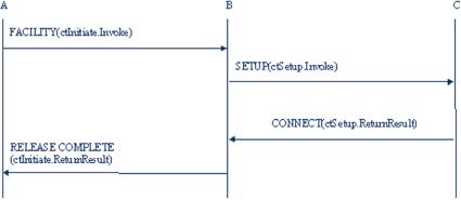
As
an example, Figure 5.15
reports the signalling
messages exchanged to perform
the Call Transfer
from
the primary call between
user A and user B to the
new call involving user B
and user C. In
particular,
when it decides to perform
the Call Transfer, user A
sends to user B the
FACILITY
message
with the APDU denoted as
CallTransferInitiate.Invoke, containing
the address of the
user
C. Using this information,
user B initiates the
procedure to open the new
call with user C
transmitting
the SETUP
message
with the CallTransferSetup.Invoke
APDU.The
user C
accepts
the call, sending the
CONNECT
message
with the appropriate
APDU.When user B
receives
the CONNECT
message,
it tears down the primary
call with user A, transmitting
the
RELEASE
COMPLETE message
with the appropriate
APDU.
Figure
5.15 Messages exchanged to
implement the CT-SS without
gatekeeper
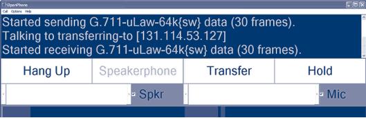
The
example refers to the case
where the gatekeeper is absent or
the direct signalling model is
adopted.
In this case, only the
software able to process and
to generate the APDUs is
necessary to
implement
the service. An example is
given in Figure 5.16 where we
report an Ohphone (an
openh323
application) interface modified
with, the addition, of a Call
Transfer Supplementary
P.158
[IP
Telephony Cookbook] /
Setting Up Advanced
Services
services
button. In this case, simply
pressing the Transfer
button
makes the application of
an
open
dialogue screen, allowing
the insertion of the H.323 ID of
the called party and
generating
the
necessary APDUs.
Figure
5.16 An example of Call
Transfer Supplementary Service
without gatekeeper -
Ohphone-
modified
interface
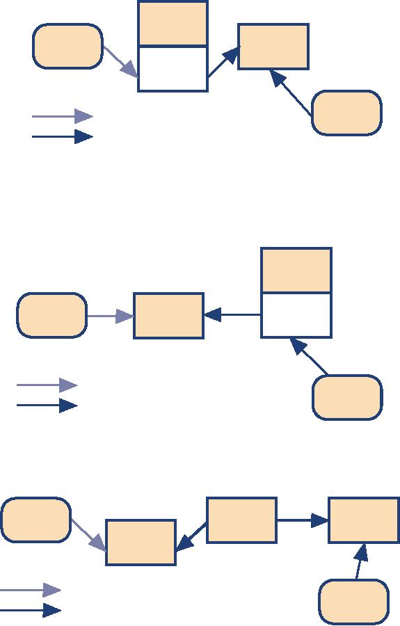
5.2.1.1.1
Gatekeeper role in the call
transfer
In
the case of the
gatekeeper-routed model, the gatekeeper
either transparently transports
or
performs
the operations necessary to
offer the service. In particular,
the gatekeeper can
provide
CT-SS,
when one or both endpoints
are unable to support the
service.
Hence,
in order to provide the
service, the gatekeeper can
decide to perform the
actions
applicable
to the transferred endpoint, to the
transferred-to endpoint or both.When
the
gatekeeper
handles the Call
Transfer signalling
on behalf of an endpoint, it should
perform
further
procedures as defined for
the transferred and the
transferred-to endpoints.
These
further procedures are the
sending of a FACILITY
message
with an appropriate
APDU
used
to inform the transferred
user (or the transferred-to
user when it manages the
signalling on
behalf
of transferred-to user) that it has
been transferred. Furthermore, the
gatekeeper should
instruct
the endpoint (or endpoints), that it
manages the signalling on
behalf of the new set
of
media
channels to connect.
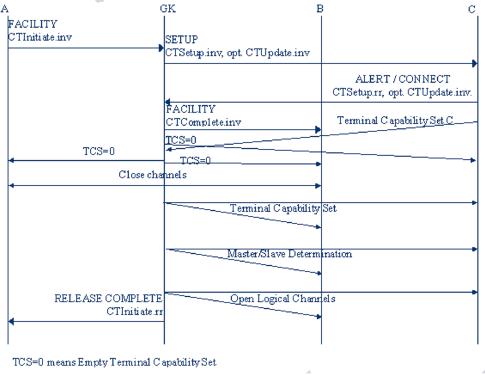
To
accomplish this, the
gatekeeper uses the H.323
procedures for third party
re-routing.These
procedures
require the gatekeeper to
send an empty terminal capability
set (one which
indicates
that
the remote entity has no
receive capabilities) to endpoints A
and B, causing A and B to
close
their
logical channels.Then, the gatekeeper
exchanges the H.245 command
end
session with
endpoint
A and sends a RELEASE
COMPLETE message
containing the resulting APDU
to
release
the call signalling
channel.
When
it receives a non-empty terminal
capability set from endpoint C,
the gatekeeper
forwards
the
capability set to endpoint B to cause it
to reset its H.245
associated state to that
which it is in
when
H.245 has just completed
(the first) terminal capability
set exchange in the initial
call
establishment
sequence.Then the gatekeeper
takes part in master/slave determination,
and opens
appropriate
logical channels with endpoint C.
P.159
[IP
Telephony Cookbook] /
Setting Up Advanced
Services
To
better understand the
signalling procedure used,
Figure 5.17 illustrates the
messages exchanged for
the
CT-SS when the gatekeeper
manages the signalling on
behalf of the transferred
user, i.e., B user.
Figure
5.17 Messages exchange for
gatekeeper-managed CT-SS
After
the reception and the
processing of the FACILITY
message,
indicating that user A wants
to
transfer
the current call, the
gatekeeper sends a SETUP
message
with a
callTransferSetup.invoke
APDU to
the transferred-to endpoint C.Then,
the reception of the
ALERTING
or
CONNECT
message
with the appropriate APDU
transmitted by the user
C
enables
the gatekeeper to send a
FACILITY
message
with the APDU informing
the endpoint B
that
it has been transferred (joining).
To
instruct the endpoint for
the new set of media
channels, the gatekeeper
sends an empty terminal
capability
set (it is defined as a
terminalCapabilitySet
message
that contains only a
sequence
number
and a protocol identifier) to endpoints A
and B, causing A and B to
close their logical
channels,
and to endpoint C, causing
this endpoint to enter in
the transmitter
side paused state.
While
in this state, an endpoint does
not initiate the opening of
any logical channels, but
accepts
the
opening and closing of logical
channels from the remote
end, based on the usual
rules, and
continues
to receive media on open logical
channels opened by the
remote endpoint.This
procedure
allows gatekeepers to re-route
connections from endpoints
that do not support
supplementary
services, and endpoints to
receive announcements (e.g.,
pre-connect call
progress)
where
the announcing entity does
not wish to receive media
from the endpoint.
The
transmitter
side paused state is
left by the endpoint on reception of
any
terminalCapabilitySet
message, other
than an empty capability set. On
leaving this state,
an
endpoint
resets its H.245 state to
that which it was in just
after the H.245 transport
connection
was
made at call establishment
time (i.e., the beginning of
phase B), but it preserves
state
information
relating to any logical channels
that are open.
P.160
[IP
Telephony Cookbook] /
Setting Up Advanced
Services
This
puts the endpoint in a known
H.245 state after the
pause, allowing an endpoint to be
connected
to a different endpoint when it is released
from the paused state.
After leaving the
transmitter
side paused state, an
endpoint proceeds with normal
H.245 procedures: it
takes
part
in master/slave determination signalling
and proceeds with normal
open logical channel
signalling
procedures.
After
these procedures, necessary to
set the new call
between B and C, the
gatekeeper sends a
RELEASE
COMPLETE message
containing callTransferInitiate
return result
APDU to
release
the call signalling channel
of the primary calls, i.e.,
between A and B.
-/
5.2.1.2
Call Diversion Supplementary
Service
The
signalling procedures and
the protocols needed to
implement the Call
Diversion
Supplementary
Service are defined in the
Recommendation H.450.3.The service
permits to a
user,
denoted as the served user
and receiving a call from an
originating user to redirect it
to
another
user, denoted as the diverted-to
user.This operation leads to
the connection of the
originating
user with the diverted-to
user, and it is possible
only when the served
and originating
users
are not in a call.There are
four kinds of call diversion
service. Supplementary Service
Call
Forwarding
Unconditional (SS-CFU) permits a served
user, independent of its
status, to forward
incoming
calls addressed to the
served user's number to
another number. CFU is provided on a
per
number
basis. On the contrary, in
the case of the Supplementary
Service Call
Forwarding
Busy
(SS-CFB), the call forwarding is
made by the served user
only when it is busy. A bit
different
is
the Supplementary
Service Call Forwarding No Reply
(SS-CFNR), where the
call
forwarding
begins when the served
user does not establish
the connection within a
defined period
of
time.
All
of these kinds of services
may be either permanently
activated or activated/deactivated
under
user
control.The user control can
be provided locally, at the served
endpoint, remotely by another
endpoint
or both. Other than the
activation/deactivation procedures, the
H.450.3 defines the
interrogation
and the registration
procedures.
The
interrogation procedure provides
information to the interrogating
endpoints such as the
activated
or deactivated state of the
supplementary service, and, if
the service is activated,
the
diverted-to
number, whether activated for
all basic services or an
individual basic service and
the
identity
of the individual basic
service.The registration permits the
provision of the
information
related
to the activated service,
and it is performed on the activation
procedure.
Indeed,
to activate these services,
the served user supplies
the diverted-to number and
optionally,
further
parameters, depending on the
capabilities of the specific
implementation.Verification that
the
diverted-to number exists may be carried
out before accepting the
activation request.
In
the same recommendation, Call
Deflection (SS-CD)is also defined,
which permits a served
user
to respond to an incoming call
offered by the served endpoint by
requesting diversion of
that
call
to another number specified in the
response. Hence, the service
does not require
activation/deactivation/information/registration
procedures.The diversion request is
only allowed
before
the called user has answered
the call and, in particular,
when the served user is in
the
alerting
state.
P.161
[IP
Telephony Cookbook] /
Setting Up Advanced
Services
On
acceptance of the CD request,
the served endpoint performs
the diversion towards
the
indicated
diverted-to number.The original call at
the served user remains in
the alerting state
and
the
served user is still able to
accept the call until
the diverted-to endpoint enters an
alerting state.
When
the diverted-to endpoint enters the
alerting state, the call to
the served user is
cleared.
5.2.1.2.1
Gatekeeper role in the call
diversion
The
gatekeeper can be either
transparent to the Call Diversion
Service or directly manage it.
In
the
first case, the implementation of
the service is directly on the
user endpoint or in the
proxy
server.
When
the service is managed by
the gatekeeper, the messages
related to the
activation/deactivation/interrogation/verification
of the diverted-to number are received
and
processed
by it, acting as a served endpoint.Thus,
when the originating user
sends the ARQ
message
to contact the forwarding terminal
for sending the
activation/deactivation/interrogation/verification
messages, the gatekeeper
responds returning the
ACF
message
containing its own call
signalling address, rather
than the call signalling
address of
the
forwarding terminal.
The
invocation of the service depends on
the kind of call diversion
invoked. In particular, when
the
SS-CFU is activated in the
gatekeeper for an incoming
call destined for user B
(being the
served
user), the gatekeeper acts
as served endpoint and invokes
the call
forwarding
unconditional
for
this call. Furthermore, if the
option served
user notification applies,
the
gatekeeper
sends the notification to
the called terminal.
In
the case of the SS-CFB,
the gatekeeper continues the
H.225 call establishment
procedure to
endpoint
B, where the user B (being
the served user) is. If
the endpoint B results busy,
i.e., if a
RELEASE
COMPLETE message
is received from endpoint B containing
cause value user
busy, the
gatekeeper acts as served endpoint
and invokes the call
forwarding on busy for
this
call.
Also in this case, the
gatekeeper sends the
notification to the called
terminal, if the
option
served
user notification applies.
For
the provision of the SS-CFNR
service by the gatekeeper,
when a call arrives,
destined for
user
B (being the served user),
the gatekeeper starts a
local no-response
timer
and continues the
H.225
call establishment procedure to endpoint
B. If the local no-response
timer
expires during
the
alerting phase of the call,
the gatekeeper acts as
served endpoint, invokes the
call forwarding
on
no
reply for this call and, if
the option served
user notification applies,
sends the
notification
to the called
terminal.
-/
5.2.1.3
Call Waiting Supplementary
Service
The
Supplementary
Service Call Waiting (SS-CW),
defined in the H.450.6
Recommendation,
permits
a busy user B to be informed of an
incoming call while being
engaged with one or
more
other
calls.
In
other words, SS-CW operates
in case of an incoming call
(from user C, calling user)
when a
busy
condition within
the endpoint is encountered. Note
that, in general, a busy
condition may
also
be encountered if the user is
busy with workflow
applications (e.g., writing
e-mails).
P.162
[IP
Telephony Cookbook] /
Setting Up Advanced
Services
When
the SS-CW is invoked, user B
is given an appropriate indication of
the waiting call and
the
calling
user C may be informed about
SS-CW being invoked at the
destination by being
provided
with
an appropriate indication. After
receiving the call
waiting indication,
user B has the choice
of
accepting, rejecting or ignoring
the waiting call. During
the call
waiting condition,
the calling
user
C has the option to release
the call or to invoke other
supplementary services, e.g.,
message
waiting
callback.
In
the case of endpoints able
to simultaneously manage different calls,
the SS-CW is invoked
only
when
an attempt for a new call
(i.e. the H.225.0 SETUP
message from user C arrives
to endpoint
B)
is made to exceed the
maximum number of calls the endpoint B
can simultaneously
hold.This
condition
leads the served endpoint B to return an
ALERTING
message
towards the calling
user
C
containing the appropriate
APDU.
Meanwhile,
the endpoint B locally provides a call
waiting indication to the
user B.The busy
User
B
can free resources to accept
a waiting call by:
-
releasing an existing call according to
the procedures of recommendation
H.225.0;
-
using the Call
Hold Supplementary Service on an existing
call according to the
procedures
of
Recommendation H.450.4;
-
using the Call
Park Supplementary Service on the
existing call according to the
procedures
of
Recommendation H.450.5.
If
the served user B accepts
the waiting call, the
served endpoint sends the
CONNECT
message
to
the calling user and
proceeds with normal call
establishment procedures.
After
the reception of the
ALERTING
message
containing the APDU indicating the
invocation
of
the SS-CW by the endpoint B,
the calling endpoint provides a call
waiting indication
to the
calling
user, which has the
following options:
-
wait until the waiting
call gets accepted
(connected) by the served
user B;
-
release the call;
-
invoke other supplementary
services, e.g. message
waiting callback;
-
perform other actions (e.g.
sending e-mail).
5.2.1.3.1
Gatekeeper role in the Call
Waiting Service
In
the case of the
gatekeeper-routed model, the gatekeeper
passes on SS-CW
operations
transparently.When
a gatekeeper has appropriate knowledge
about the served endpoint B
status, it
may
act on behalf of the served
endpoint by means of inserting the
APDU indicating the
invocation
of the CW-SS into an ALERTING
message received from endpoint B
before sending
on
the ALERTING message towards
the calling endpoint.
-/
5.2.1.4
Supplementary services (H.450)
support in popular
gatekeepers
The
Cisco MCM Gatekeeper does
not support any H.450
features, even though it is,
itself,
capable
of H.323 proxying. However,
Cisco gateways do support an
extensive range of
H.450
features
and can play a significant
role in supporting supplementary
services for
H.450-capable
endpoints
that would like to reach
the PSTN.
P.163
[IP
Telephony Cookbook] /
Setting Up Advanced
Services
The
RADVISION ECS Gatekeeper,
being based on a H.323 v.4
protocol stack, implements a
number
of the H.450 features. On
the ECS configuration interface,
check the Settings
tab,
under
the
category `Supplementary Services', where
you can enable the
following:
-
Unconditional forward (H.450.3):
endpoints may select to
redirect calls to other
endpoints in
all
cases;
-
Forward on busy (H.450.3):
endpoints may select to
redirect calls to other
endpoints when they
are
themselves busy;
-
Forward on no response (H.450.3):
endpoints may select to
redirect calls to other
endpoints
when
they could not respond to a
call after x minutes.
After
enabling the above services,
the gatekeeper administrator
can define forwarding rules
by
utilising
the Forwarding
tab.
Rules for specific endpoints
(Standard), as well as
mass-application
(Wildcard)
rules for whole prefixes
can be applied for all
three forwarding conditions:
unconditional,
on
busy, on
no
answer.
For
all supplementary services to
function, the administrator
must enable full routing
mode
(Settings
tab,
category Calls). Make
note that the ECS
administrator can also
initiate calls
between
endpoints, by using the
Call
Control tab,
and the Make
Call button.
The
GNU Gatekeeper does not
support any H.450 features
either. However, some dynamic
routing
functionality can be implemented by
utilising the `virtual queues' or
`CTI agents' feature
of
the GNU Gatekeeper, which
allows the operation of a
simple model of aliasing a name
and the
forwarding
of calls to a dynamic queue of `agent'
endpoints.
-/
5.2.2
Supplementary services using SIP
This
section demonstrates the use
of legacy telephony features in SIP.
Note that the general
SIP
design
concept has been to leave
the description of such features
out of protocol specifications. It
is
the responsibility of implementations to introduce
new services on top of well-defined
protocol
specification.There
are only a few well-defined
protocol elements such as REFER method
(RFC
3515).
Such elements can be used
for a variety of services without
having to undergo the
burdensome
standardisation process again
and again.With the
particular REFER example,
the
REFER
method may be used for
several variations of call
transfer, the click-to-dial
application as
described
in the next section, interaction
with conference bridges, etc.The
application logic may
be
completely hidden in a SIP element, or it
can use some established
service-building
mechanisms
such as Call Processing
Language or SIP-CGI (RFC
3050).
To
show the proper use of
protocol elements for building
frequently-used services, the
IETF
issued
an informational document, `Session
Initiation Protocol Service Examples'.The
document
presents
call flows for many
services, including on-hold,
transfers and conferencing.
Another
essential
document is `A Call Control and
Multi-party Usage Framework for
the Session
Initiation
Protocol (SIP)' by Rohan Mahy et al.The
document shows the concepts of
building
more
complex services based on
SIP and also presents
multiple design choices for
many of them.
Yet
another document related to
implementation of telephony services is
`Third-party Call
Control',
which shows how to implement
complex multi-stage multi-party
telephony
conversations
using external SIP-based call
control.
P.164
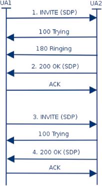
[IP
Telephony Cookbook] /
Setting Up Advanced
Services
The
rest of this section
demonstrates the most
frequently used SIP
services, gives a brief
overview
on
provisioning of such services and
also describes what the
signalling looks
like.
-/
5.2.2.1
On-hold
With
SIP, on-hold
is implemented as a
peer-to-peer feature. A phone
putting the other
telephone
on hold does so by sending a
specially-formed re-INVITE
request.
In response to
such
a request, the other phone
stops sending media to save
bandwidth and it indicates to
the user
that
he is on hold. (It may be
silent, display the status
using user interface, play
local music, etc.)
There
are subtle differences in
how on-hold
is
signalled in earlier and current
SIP versions. RFC
2543
used a dummy IP address
0.0.0.0 to indicate an on-hold
condition
whereas RFC 3261
uses
SDP
send only attribute. Call-flow on
Figure 5.18 presents
on-hold
signalling
implemented
according
to RFC 2543.The key message
is re-INVITE, number 3,
which puts the other
party
on
hold.The SDP payload of
numbered SIP messages is
shown in detail (SIP headers
have been
removed
because they are not
important in this
case).
Figure
5.18 On-hold call
flow
The
following message is regular
INVITE
establishing
a call
1.
INVITE
[SIP
headers not shown]
v=0
o=Cisco-SIPUA
997 27044 IN IP4
192.168.2.32
s=SIP
Call
c=IN
IP4 192.168.2.32
P.165
[IP
Telephony Cookbook] /
Setting Up Advanced
Services
t=0
0
m=audio
21112 RTP/AVP 0 8 18
101
a=rtpmap:0
PCMU/8000
a=rtpmap:101
telephone-event/8000
a=fmtp:101
0-15
The
previous INVITE is replied using
the following 200 OK
2.
200 OK
[SIP
header not shown]
v=0
o=CiscoSystemsSIP-GW-UserAgent
2451 1894 IN IP4
195.37.77.110
s=SIP
Call
c=IN
IP4 195.37.77.110
t=0
0
m=audio
18202 RTP/AVP 0
c=IN
IP4 195.37.77.110
a=rtpmap:0
PCMU/8000
a=direction:passive
The
following message puts the
remote party on hold. Note
the 0.0.0.0 on the line
beginning
with
c=.
3.
re-INVITE
[SIP
headers not shown]
v=0
o=Cisco-SIPUA
4919 16082 IN IP4
192.168.2.32
s=SIP
Call
c=IN
IP4 0.0.0.0
t=0
0
m=audio
21112 RTP/AVP 0 8 18
101
a=rtpmap:0
PCMU/8000
a=rtpmap:101
telephone-event/8000
a=fmtp:101
0-15
The
following message confirms the on
hold state.There is nothing
special in the SDP
4.
200 OK
[SIP
headers not shown]
v=0
o=CiscoSystemsSIP-GW-UserAgent
2451 1895 IN IP4
195.37.77.110
s=SIP
Call
c=IN
IP4 195.37.77.110
t=0
0
P.166
[IP
Telephony Cookbook] /
Setting Up Advanced
Services
m=audio
18202 RTP/AVP 0
c=IN
IP4 195.37.77.110
a=rtpmap:0
PCMU/8000
a=direction:passive
-/
5.2.2.2
Call transfer
The
call transfer is one of the
most frequently used
telephony services.The protocol element
used
in
SIP to implement call
transfer is the REFER
method.The
REFER
method is a
very powerful
mechanism,
which allows anybody to ask
a SIP device to initiate a
call to a specific
destination.
Call
transfer is only one
application which relies on
REFER
-
click
to dial and
conference
management
can utilise REFER
as
well.
Even
call transfer may be implemented in a
variety of ways in SIP telephones.
Unattended
transfer
(also
called Blind
Transfer)
transfers a call participant to another
party, whereas the
transfer
originator drops the initial
conversation. In Attended
transfer (also
called Transfer
with
consultation), the
transferring agent first initiates a
short conversation with the
transfer
target
before connecting it to the
transferred party.
Other
variations may include a short
introductory conference during
the call transfer or
keeping
the
original conversation active
until the transfer succeeds.
(the NOTIFY
request
is used to
report
on success of call transfer in
SIP.)
The
following call flow
demonstrates the use of
REFER
for
unattended call transfer.The
key
requests
are REFER
by which
the called party suggests
that the calling party
establish a
conversation
with the transfer target.The
calling party does so by sending
the INVITE.The
called
party exits the original
conversation by sending BYE
without
awaiting the completion of
the
call transfer.
The
following REFER
message
(red in the call flow)
asks the calling party to
establish a call to
the
transfer agent. Note that
the message contains the
Refer-To
header
field containing SIP URI
of
the transfer agent and
Referred-By
header
field which contains the
SIP URI of the
initiator
(the
called party).
REFER
sip:195.37.77.101:5060;lr SIP/2.0
Via:
SIP/2.0/UDP 192.168.2.32:5060
From:
<sip:callee@iptel.org>;tag=00036bb90fd300
To:
<sip:caller@iptel.org>;tag=992d8f53-ca7e
Call-ID:
90bdee69-eb4f@192.168.0.130
CSeq:
103 REFER
Contact:
sip:callee@192.168.2.32:5060
Route:
<sip:caller@193.175.135.38:40012>
Content-Length:
0
Refer-To:
sip:transfer_agent@195.37.77.101
Referred-By:
<sip:callee@iptel.org<
P.167

[IP
Telephony Cookbook] /
Setting Up Advanced
Services
Transfer
Agent
Calling
party
Called
party
Proxy
INVITE
100
Trying
INVITE
100
Trying
200
OK
200
OK
ACK
ACK
REFER
REFER
202
Accepted
202
Accepted
NOTIFY
NOTIFY
INVITE
100
Trying
INVITE
100
Trying
200
OK
200
OK
BYE
BYE
200
OK
200
OK
200
OK
200
OK
ACK
ACK
Figure
5.19 Call transfer call
flow
The
following INVITE
message
establishes a call from the
calling party to the transfer
agent.
Note
that the value from
the Refer-To
header
field of the REFER
message
has been put into
the
Request-URI
and
To
header
field.
INVITE
sip:transfer_agent@195.37.77.101
SIP/2.0
Via:
SIP/2.0/UDP 192.168.0.130
From:
<sip:caller@iptel.org>;tag=32e189db-ec7e
P.168
[IP
Telephony Cookbook] /
Setting Up Advanced
Services
To:
<sip:transfer_agent@195.37.77.101>
Contact:
<sip:caller@192.168.0.130>
Call-ID:
205e377f-7042-b00c-0@192.168.0.130
CSeq:
20142 INVITE
Max-Forwards:
70
Content-Type:
application/sdp
Content-Length:
258
v=0
o=caller
0 0 IN IP4 192.168.0.130
s=-
c=IN
IP4 192.168.0.130
t=0
0
m=audio
5004 RTP/AVP 0 8 4 18 2 15
a=ptime:20
a=rtpmap:0
PCMU/8000
The
following BYE
message
(green in the call flow)
terminates the call between
calling party and
called
party.
BYE
sip:195.37.77.101:5060;lr SIP/2.0
Via:
SIP/2.0/UDP 192.168.2.32:5060
From:
<sip:callee@iptel.org>;tag=00036bb90fd3000
To:
<sip:caller@iptel.org>;tag=992d8f53-ca7e-c73f
Call-ID:
90bdee69-eb4f-3e1c-9833-499857a5b2b2@192.168.0.130
CSeq:
104 BYE
Content-Length:
0
Route:
<sip:caller@193.175.135.38:40012>
-/
5.2.2.3
Unconditional call
forwarding
A
user's ability to determine call
processing is a great strength of IP
Telephony.With SIP in
particular,
users are able to associate
any number of devices with
their address of record.
SIP
telephones
register their whereabouts automatically
using the SIP
REGISTER request.
Users
may
also introduce additional contacts by
means of provisioning. Upon receipt of an
incoming
call
request (INVITE
method), a
proxy server forwards the
request to all registered
contacts.
Eventually,
all registered phones start
ringing in parallel and the
conversation begins with
the
device
which the user picks
up.
The
ability to manipulate contacts
allows users to determine handling of
incoming calls. For
example,
a user may wish to decide
that all incoming calls
will ring his cell phone as
well.The
following
set of examples shows how
the manipulation of registered user
contacts can be used
for
forwarding
purposes.The examples use
SER and its command line
control tool, lserctl,
to
manipulate
contacts of a user.Typically, this
job is done through a Web
interface such as
Serweb
because
it is more convenient.The commands used
are ul
add USER SIP_CONTACT for
introducing
a new forwarding address and
ul
show USER for
displaying currently registered
contacts.
P.169
[IP
Telephony Cookbook] /
Setting Up Advanced
Services
First,
the current status of registered
contacts is inspected.The command reveals
that a SIP phone
registered
a contact from IP address
212.202.42.68.
jiri@fox:~$
serctl ul show jiri
<sip:212.202.42.68:55723<;q=0.00;expires=272
To
enable forwarding of incoming calls
also to cell phone, introduce contact to
the PSTN
gateway.
If a call arrives, the proxy
server will ring both the
previously-registered SIP phone
and
the
manually-provisioned cell phone
contact.
jiri@fox:~$
serctl ul add jiri
sip:123456@iptel.org
sip:123456@iptel.org
200
Added to table
('jiri','sip:123456@iptel.org')
to 'location'
jiri@fox:~$
serctl ul show jiri
<sip:123456@iptel.org>;q=1.00;expires=1073741820
<sip:212.202.42.68:55723>;q=0.00;expires=21
-/
5.2.2.4
Conditional forwarding
Called
parties frequently wish to
redirect incoming calls to an
alternative destination if
the
primary
destination fails to answer.The
reasons for failure are
multi-fold.They may include a
busy
called
party, disconnected called
party's phone, user who
currently does not answer or
user
denying
the incoming call.The alternative
destination is typically a voicemail
system but it may be
also
another human or some other
SIP device.
The
following configuration fragment
demonstrates how set up such
a feature using SER:
#
if invitation recipient off-line,
forward to voicemail
if
(!lookup("location")) {
rewritehostport("voicemail.iptel.org");
t_relay_to_udp("voicemail.iptel.org",
"5060");
break;
};
#
user on-line, forward INVITE
to him; also set up a
failure
#
handler so that we can
redirect to voicemail if
the
#
call is not established
successfully
if
(method=="INVITE") {
t_on_failure("1");
};
t_relay();
....
#
alas, the call was
not established successfully;
well,
#
let's retry with voicemail
then
failure_route[1]
{
revert_uri();
# resend to voicemail with
original request URI
P.170
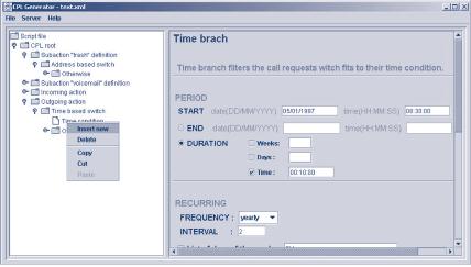
[IP
Telephony Cookbook] /
Setting Up Advanced
Services
rewritehostport("voicemail.iptel.org");
append_branch();
t_relay_to_udp("voicemail.iptel.org",
"5060");
}
Whereas
this example demonstrates a
global site policy which is
applied to each user,
some
subscribers
may wish to formulate their
specific call processing
preferences. How the
preferences
are
formulated and provisioned in the
SIP server is not
necessarily governed by standards.
SIP
servers
may have their own
proprietary user-provisioning interfaces,
typically with a Web
front-
end.
On the other hand, a
standardised way of call
handling allows easier
service portability.The
IETF
standard for describing
called party's preferences is
called Call Processing
Language, CPL. In
short,
it is a simple XML-based language
that allows subscribers to determine
how the server
handles
calls for them. It is a
special-purpose language that
supports the specification of
most
common
types of call processing.
CPL does not allow
script writers to affect the
behaviour of the
server
in a way which could compromise
the security of the
server.
Whereas
it is simple enough, most
users will not be willing to
write SER scripts. It is
envisioned
that
CPL scripts will be
generated and edited by
applications with a convenient
user interface.
The
following picture shows a screen
snapshot of iptel.org's CPL
editor.
Figure
5.20 CPL editor
-/
5.3
Multipoint conferencing
Multi-party
conversations are known from
the PSTN world.The function
is often provided by a
company's
PBX. It is also possible to
use a commercial service. A central
part of the service is
the
Multipoint
Conference Unit (MCU). In
order to use the service, a
session leader must make
a
reservation
for the session at the
MCU. Every MCU has a different interface
to do so. MCUs in
the
IP Telephony world usually
offer a Web-based form for
this.
At
the time the conference is
planned, each user calls
the phone number of the MCU.
After that,
a
number must be dialled to denote
the session that the
user wants to join, because
an MCU can
support
multiple sessions at the
same time. A password is
required to prevent uninvited
parties
from
joining the conference. Some
MCUs can initiate the
set up of the conference
itself by
dialling
all the parties. It needs to
know everyone's phone number in
advance, of course.
P.171
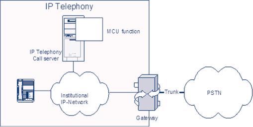
[IP
Telephony Cookbook] /
Setting Up Advanced
Services
The
main function of the MCU starts at
this point in the
conference: it receives the
audio signals
of
every party in the session,
mixes the sources and
copies the result to
everyone except for
the
source
party.This happens in real time, so
everyone will hear
everyone.This way of conversing
has
its
specific ways of interaction between
the parties. If a party
wants to speak, it should be
clear that
the
previous party has ended his
part of the conversation.When
collisions occur, it is useful if
the
session
leader gives the word to
one of those who wish to
speak.These aspects have
been
investigated
in the social-cultural area, but
are not part of this
cookbook.
Now
that the functionality is
known in general, more details on
the case of IP Telephony
MCUs
can
be given. An MCU can be obtained
either in hardware or in software.
Many gatekeepers are
equipped
with built-in MCU software
functionality. In case of a hardware
MCU, the main
interface
is, of course, an Ethernet connection. From a
functional point of view, users
cannot
approach
the MCU directly over IP. No
matter whether H.323 or SIP
are used for setting
up
regular
two-party calls, a user can
only dial in to the MCU through a
gatekeeper or SIP Proxy.
Parties
that use a PSTN phone
can also join a conference
by means of the IP-to-PSTN
gateway.
Figure
5.21. MCU function in
gatekeepers
Modern
MCUs can support both audio
and video.The calling parties must
support the audio
and
video
codec that the MCU has on
board. Some MCUs have
the possibility to transcode
between
codecs,
enabling users with different
codecs to join the same
conference. If video is also
distributed
by an MCU, the video streams
cannot be mixed. One way
this distribution
mechanism
is
implemented is that only the video
signal of the source with
the loudest audio signal
is
transmitted
to all users at that point
of time (this in audio
switching mode).There are
other
options,
such as chair-controlled, in which the
chair can lock the video
(and possibly audio
too)
on
one participant, or presentation mode.
One participant is chosen and both
audio and video are
locked
on the presenter; the rest
of the audience can only
listen. Some MCUs offer a
Continuous
Presence
mode, in which the video
signals is displayed in a matrix
that shows all users to
every
user.
Modern
MCUs support other layouts
as well. An alternative to using an MCU
in the IP world is
to
use IP Multicast. In this
case, all parties transmit
their audio (and video) over
a Multicast
channel.
All users must tune in to
the channels of everyone
else.This means that the
total amount
data
traffic increases with every
user that joins the
conference. Unfortunately, few
networks
support
Multicast.
P.172
Table of Contents:
- INTRODUCTION:Goal, Reasons for writing this document, How to read this document
- TECHNOLOGICAL BACKGROUND:Components, Terminal, Protocols, SIP
- IP TELEPHONY SCENARIOS:Long-distance least cost routing, Integration of VoIP and videoconferencing
- SETTING UP BASIC SERVICES:General concepts, Dial plans, Authentication
- SETTING UP ADVANCED SERVICES:Gatewaying, Accounting gateways, Multipoint conferencing
- SETTING UP VALUE-ADDED SERVICE:Web integration of H.323 services, Web integration of SIP services
- INTEGRATION OF GLOBAL TELEPHONY:Technology, Call routing today,
- REGULATORY / LEGAL CONSIDERATIONS:Regulation of Voice over IP in the European Union, Numbering
- ANNEX A. European IP Telephony Projects:Evolute, SURFWorks, VC Stroom
- ANNEX B. IP Telephony Hardware/Software:Softphones, Hardphones, Gateways
- GLOSSARY:Call Processing Language, Gatekeeper, Media Gateway Control Protocol