 |
Serial Data Communications Over Fiber Optic Cable |
| << Exploiting The Advantages Of Fiber Optic Cable In the Industrial Environment:The Problem of Interference |
| Standards >> |
Page
66 of 97
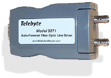
Figure
5-11: The Model 9271
Fiber Optic Auto Powered
Line Driver features a
standard DB9
interface
The
Model 9271's ability to
take/direct data from/to
this interface without any
conversion eases
implementation.
A highly flexible solution,
the Model 9271 has been
optimized for 62/125 fiber
cables,
and
is compatible with other
sizes as well. It features
industry-standard ST cable port
connectors, plus a
DTE/DCE
switch to reverse Pins 2 and 3 of the
RS-232 connector to accommodate equipment
with
different
data output
configurations.
Operating
current for the Model 9271
is derived from the transmit
data line, with a power
budget of 12
dB
when using 62/125 cable. For
applications requiring a dedicated
power source, the unit can
be
ordered
with a wall-mounted power pack
(available as the Model
9271A).
The
Model 9271 incorporates clips in
the outer casing so that the
unit can be securely attached to a
DIN
rail,
wall, table or desk in an
organized manner.
This
is an appropriate point to discuss DIN
Rail mounting in greater detail. DIN
Rail mounting is a
cabling
system that was developed
specifically for factory
automation. Only recently
has it been
discovered
for use with data
equipment. This system is
simple and straightforward. It uses a
steel
channel
called a DIN Rail. The DIN
Rail has slotted holes
for mounting and is normally
mounted in a
horizontal
position. DIN Rail products
like the Model 9271 are
then placed on the Rail by
snapping
them
in place after which the
wiring is completed.
CHAPTER
6
SERIAL
DATA COMMUNICATIONS OVER FIBER OPTIC CABLE
In
the premises environment the
most common form is serial
data communications. This is
the situation
where
data embarks from the Source at a
serial interface and enters the
User at a serial interface.
Serial
data
communications is everywhere in the
office, campus or industrial environment.
It is found, on the
factory
floor, in the hospital, in
the retail establishment and
out in the oil patch.
This list goes on and
on.
In
this chapter we consider
premises serial data
communications carried out
using fiber optic data
links.
Page
67 of 97
Products
are introduced that support
this type of communications.
Some of these products have
been
introduced
in previous chapters. Others are
new. All of these products
are available from
Telebyte.
Model
271 Fiber Optic Auto Powered
Line Driver
The
Model 271 Fiber Optic Auto
Powered Line Driver is pictured as a
stand-alone unit in Figure
6-1.
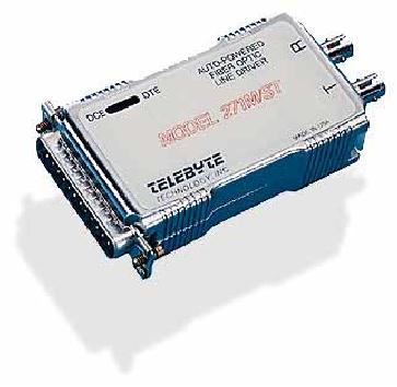
Figure
6-1: Model 271 - Fiber
Optic Auto Powered Line
Driver
The
Model 271 Fiber Optic Auto
Powered Line Driver is a short
haul modem that employs an
RS-232
data
interface and transmits the
data on a fiber optic cable.
This modem provides, full
duplex,
asynchronous,
data communications over two
fiber optic cables. The
length of the fiber optic
cable can
be
up to 2 km and the data rate as high as
56 KBPS. Performance of the
unit is optimized for
62.5/125-
fiber
optic cable. However, the
modem can also be used with
fiber optic cable having
other dimensions.
The
operating power for the
Model 271 Fiber Optic Auto
Powered Line Driver is derived
from the
transmit
data line. This is a real
convenience when an electrical
outlet is not readily
available. The
Model
271 is equipped with a DTE/DCE switch
that reverses pins 2 and 3 of
the RS-232 connector.
This
allows
the modem to support
terminals, printers, computers or
any other RS-232 based
device. The fiber
port
of the unit employs ST
connectors.
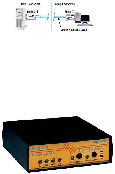
One
application of the Model 271 is
illustrated in Figure 6-2.
Notice while this
application deals with
the
factory
environment there is no card cage.
Rather, the application is
dealing with the situation
where
there
is the need for a data
communication link between a
mini-computer located in the
front office of a
company
and a PC located on the company's
factory floor. Both the
front office and the factory
floor are
in
the same building.
Page
68 of 97
Figure
6-2: Example Application of the
Model 271
Data
communication carried out
strictly in the front office
may be quite reliable over
copper cable.
However,
because the data
communication link in this
application traverses the boundary to
the factory
floor
there is a need for the
extra reliability provided by
fiber optic cable.
Model
274 RS-232 Single Fiber,
Sync/Async Line
Driver
The
Model 274 RS-232 Single
Fiber, Sync/Async Line
Driver is pictured as a stand-alone
unit in Figure
6-3.
Figure
6-3: Model 274 - RS-232
Single Fiber, Sync/Async Line
Driver
The
Model 274 is a unique short
haul modem for use on a
fiber optic data link. To
achieve full duplex
communication
it only requires one multi-mode
62.5/125-fiber optic cable. Most
fiber optic data
communication
networks require two cables
to achieve full duplex operation. In
fact, if standard duplex
fiber
optic cables have been
installed the Model 274 can be
used to double the
capacity.
The
Model 274 receives and delivers data
through an RS-232 interface.
This unit supports
nine
synchronous
data rates up to a maximum of 256
KBPS. It supports asynchronous
data rates up to 38.4
KBPS.
Furthermore, it supports two pairs of
handshake control signals, RTS/CTS and
DTR/DSR.
The
Model 274 has operator selectable,
built-in diagnostics. These include
Local Loop-back and
Remote
Page
69 of 97
Loop-back.
The
data interface to the modem
is a female DB25 connector.
The fiber port interface is
a ST connector.
LED's
for TD, RD, control
signals and loop-backs allow
the unit to assist in
verifying link
operation.
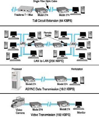
The
four illustrations in Figure
6-4 indicate how the
Model 274 may be employed in
typical
applications.
Figure
6-4: The Model 274
employed in typical
applications
Model
279 Multi-Mode to Single-Mode Fiber
Optic Converter
The
Model 279 Multi-Mode to Single-Mode
Fiber Optic Converter
provides such conversion. It
is
pictured
in Figure 6-5.
The
Model 279 Multi-Mode to Single-Mode
Fiber Optic Converter
provides transparent
conversion
between
multi-mode fiber optic cable
signals and single-mode fiber
optic cable signals. As alluded
to
above
single-mode fiber optic cable can
transmit data over much
longer distances than
multi-mode fiber
optic
cable. Single-mode operation is at a 1310 nm
wavelength. Multi-mode operation is at
850 nm
wavelength.
Page
70 of 97
Figure
6-5: Model 279 - Multi-Mode
to Single-Mode Fiber Optic
Converter
There
are many applications for
the Model 279. This
unit can be employed as an individual
converter. A
pair
of these units can also be employed as
single-mode, fiber optic cable, and
short haul modems in
order
to signal over long link
distances. The unit can also be used
when the optical fiber
type of the
equipment
is not compatible with the
installed type of fiber
optic cable e.g., you have a
modem
transmitting
multi-mode signals but the
installed fiber optic cable is
single-mode.
The
Model 279 operates at speeds
from DC to 2.5 MBPS over
links that can be as much as 15 km
long.
Since
operation at DC is possible there is no
signal that can be used to
perform automatic gain
control.
However,
the unit allows the
needed control, to be executed
manually, by a Line Loss
Switch.
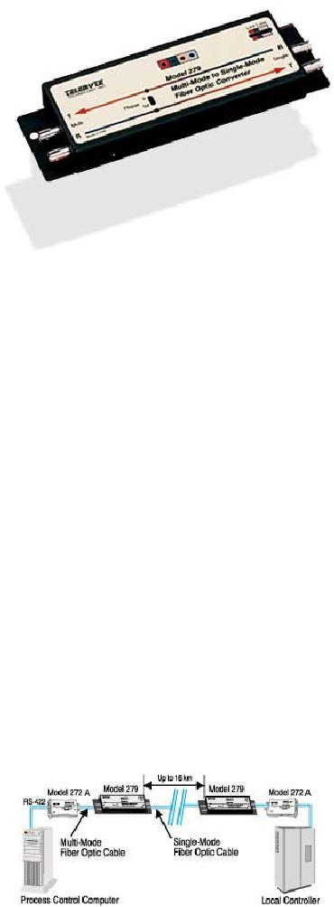
The
Model 279 is illustrated in one of many
possible applications in Figure 6-6.
This is an application in
an
industrial environment. There
are two manufacturing
facilities in the company
associated with this
application.
These two facilities are
remotely located from one
another. They are 15 km apart.
The
process
control computer located on
the floor of one facility
needs to communicate with
the local
controller
in the other facility. Both
the process control computer
and the local controller
employ the
RS-422
interface. As shown in Figure
6-8 both the process
control computer and the
local controller
have
data converted to fiber
optic signals using the
Telebyte Model 272A.
However, these signals
are
multi-mode.
In order to cover the large
15 km distance between the two
facilities single-mode fiber
optic
cable
must be employed. Placing a
Model 279 at the fiber
output of each Model 272A
allows the
conversion
to the needed single-mode
signals.
Table of Contents:
- Introduction:The Fundamental Problem of Communication, Program
- The Fiber Optic Data Communications Link For the Premises Environment:Fiber Optic Cable
- Exploiting The Bandwidth Of Fiber Optic Cable-Employment by Multiple Users:Sharing the Transmission Medium
- Exploiting The Delay Properties Of Fiber Optic Cable For LAN Extension:Brief History of Local Area Networks
- Exploiting The Advantages Of Fiber Optic Cable In the Industrial Environment:The Problem of Interference
- Serial Data Communications Over Fiber Optic Cable
- Standards
- Glossary