 |
OPTICAL TRANSMITTER CIRCUITS:Audio Amplifier with Filters, Pulsed Light Emitters |
| << OPTICAL RECEIVER CIRCUITS:Current to Voltage Converter Circuits, Post Signal Amplifiers |

Chapter
Seven
OPTICAL
TRANSMITTER CIRCUITS
As
in radio transmitters, optical
through-the-air transmitters must
rely on some type of
carrier
modulation
technique to transmit information.
The method most often chosen
for optical systems is
a
simple on/off light pulse
stream. The position or frequency of
the light pulses carries
the
information.
Flashing roadside warning
lights and blinking radio
tower lights are examples of
low
speed
optical transmitters. To transmit
human voice information you
will need to increase the
light
flashing
rate to at least 7,000 flashes per second.
For television you will need
about 10 million
flashes
per second. Although much of the
discussion in this book will
focus on voice audio
transmitters,
you can apply many of the
same techniques for video
and computer data
transmission.
An
audio signal optical
transmitter can be broken down
into 6 sections: an audio
amplifier, a voice
frequency
filter, a voltage to frequency
converter, a pulse generator, a
light emitter and a
light
collimator.
However, if you are sending
only an on/off control
signal you won't require an
audio
amplifier
or a voltage to frequency converter.
Transmitters used for
television or high
speed
computer
data will use variations of
the same methods used
for voice but would
require much
higher
modulation rates.
Audio
Amplifier with
Filter
An
electret microphone is commonly
used to detect the speech
sound. These devices are quite
small
in
size but are very sensitive.
Unlike passive microphones, an
electret microphone contains
an
internal
FET transistor buffer
amplifier and therefore requires an
external DC voltage source to
supply
some power to the assembly.
Another benefit of the
electret microphone is that it
produces
an
output signal that has
sufficient drive to go straight
into an audio amplifier
without any
impedance
matching circuitry as some
other microphones
require.
Since
the development of the
telephone, extensive testing
has concluded that
frequencies beyond
3.5KHz
are not needed for
voice audio communications.
Therefore, most telephone systems
reject
frequencies
higher than 3.5 KHz. An
optical system designed for
voice audio transmission
can
therefore
get by with a fairly low
pulse rate. Usually a 10,000
pulse per second signal will
be
sufficient.
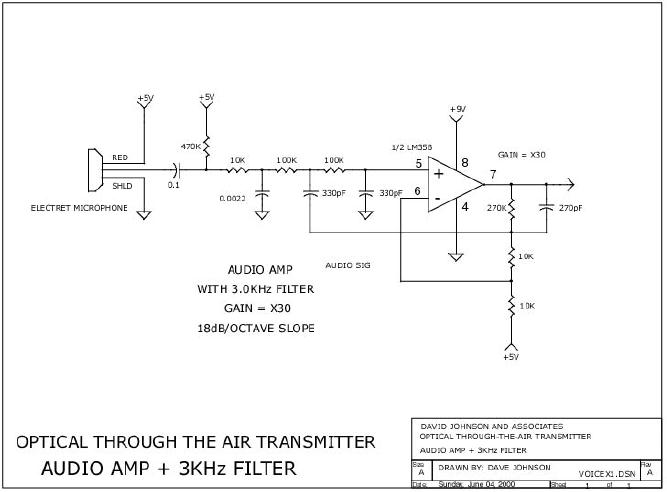
Figure
7a on page 65 shows a
simple operational amplifier
circuit that not only
amplifies (gain of
x30)
the speech signal from an
electret microphone but also
removes the high
frequency
components
not needed when transmitting
voice information. The "low
pass" filter rejects
signals
above
3.5KHz with a 18db/octave slope. A
low pass filter is recommended to
prevent erratic
operation
from audio frequencies
higher than the modulation
frequency.
Voltage
to Frequency Converter
Although
many kinds of pulse
modulation schemes are possible,
the most efficient method
for
transmitting
voice audio is pulse
frequency modulation. The
frequency modulated pulse
stream
carries
the voice information. The
voice audio, whose upper
frequency is restricted to less
than
Page
59
of 68
Optical
Through-the-Air Communications Handbook
-David A. Johnson, PE
3.5KHz,
is connected to a voltage to frequency
converter. The converter is
essentially an oscillator
whose
frequency is shifted up and down
according to the amplitude and
frequency of the
audio
signal.
A shift of +-20% is usually
sufficient for voice
signals. As discussed above, a
voice audio
optical
transmitter only requires a
pulse rate of about 10,000 pulses per
second. The most
important
requirement
of the conversion is that it
must be linear in order to
reproduce the audio
accurately.
Circuits
using a non-linear VCO or
voltage to controlled oscillator will
always lead to an abnormal
sounding
voice signal when the
signal is later detected by an
optical receiver.
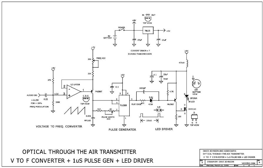
Figure
7b on page 66 is an
example of a linear VCO
whose center frequency can be
adjusted from
about
8Khz to about 12KHz. It is
made from two separate
circuits. An operational amplifier and
a
transistor
form a current source which
charges a 0.,001uF capacitor at a
very linear rate.
The
upward
ramping voltage across the
capacitor is connected to a C-MOS
version of the popular
555
timer
whose internal voltage
thresholds control the
amplitude of the saw tooth
waveform that
results.
The capacitor is thus charged by
the current source producing a
linear ramp waveform
and
is
quickly discharged though the
timer, producing a pulse.
With the values shown,
the 555 produces
an
output pulse width that can
be adjusted from about 800 nanoseconds to
about 1.2
microseconds.
As
the audio signal that is AC
coupled to the current source,
swings up and down, the
capacitor
charging
current is increased and decreased
from a nominal level. The
modulated current source
thus
produces a frequency modulation of the
output pulse stream from the
555 timer. With the
values
shown, the circuit only
requires an audio amplitude of
about +-0.1 volts to produce
a +-20%
frequency
shift.
Other
linear VCO circuits are also
possible using the C-MOS
phase locked loop IC
(CD4046), the
LM766
or the National Semiconductor
LM331. Sometime in the future I will
include some VCO
circuits
using these parts.
Pulsed
Light Emitter
Whether
the through-the-air light
transmitter is used to send
high-speed computer data or a
simple
on/off
control message, the light
source must be intensity modulated in
some unique fashion so
the
matching
light receiver can distinguish
the transmitted light signal
from the ever present
ambient
light.
As discussed in the section on
light detectors, silicon PIN
light detectors convert light
power
into
current. Therefore, to aid the
distant light receiver in
detecting the transmitted
signal, the light
source
should be pulsed at the
highest possible power level. In
addition, as discussed in the
section
on
light emitters, an LED can be
very effectively used to
transmit voice information. To
produce the
highest
possible light pulse intensity
without burning up the LED,
a low duty cycle drive
must be
employed.
This can be accomplished by driving
the LED with high
peak currents with the
shortest
possible
pulse widths and with the
lowest practical pulse
repetition rate. For standard
voice systems,
the
transmitter circuit can be pulsed at
the rate of about 10,000 pulses per
second as long as the
LED
pulse width is less than
about 1 microsecond. Such a
driving scheme yields a duty
cycle (pulse
width
vs. time between pulses) of
less than 1%. However, if
the optical transmitter is to be
used to
deliver
only an on/off control
signal, then a much lower
pulse rate frequency can be used. If a
pulse
repetition
rate of only 50 pps were
used, it would be possible to transmit
the control message
with
duty
cycle of only 0.005%. Thus,
with a 0.005% duty cycle,
even if the LED is pulsed to
7 amps the
average
current would only be about
300ua. Even lower average
current levels are possible
with
simple
on/off control transmitters, if
short multi-pulse bursts are
used. Such a method might
find
uses
in garage door openers, lighting
controls or telemetry
transmitters.
Page
60
of 68
Optical
Through-the-Air Communications Handbook
-David A. Johnson, PE
To
obtain the maximum practical
efficiency, the LED should
be driven with low loss
transistors.
Power
field effect transistors
(FET) are ideal. These devices can
efficiently switch the
required high
current
pulses as long as their gates
are driven with pulses with
amplitudes greater than about
7
volts.
Figure
7b on page 66 illustrates
a FET driver that is used to
power a LED directly
without
any
current limiting resistor.
The circuit takes advantage of
the rather high voltage
drop of the LED
at
high current levels to self
limit the LED current.
With the components selected,
the LED current
will
be about 5 amps peak when
used with a 9v supply. The
inductor capacitor network
between the
LED
and the power supply acts as
a filter and helps keep the
high current signals from
interfering
with
other parts of the transmitter
circuit sharing the 9v
supply.
Light
Collimator
For
long range applications, the
light emitted by the LED
must be bent into a tight
light beam to
insure
that a detectable amount of light will
reach the distant light
receiver. For most
LED
applications
a simple plastic or glass
lens will do. As discussed in
the section on light
emitters, the
placement
of the lens in front of the
light source has the effect
of reducing the exiting
light
divergence
angle. Selecting the right
lens for the application is
dependent on the type of LED
used.
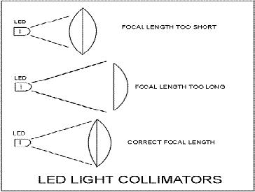
As
illustrated in figure
7c, the lens's
focal length should be
picked so it can capture most
of
the
emitted light. LEDs with
wide
divergence
angles will require lenses
with
short
focal lengths and LEDs with
narrow
divergence
angles can use lenses with
long
focal
lengths. Keep in mind that
the LED
divergence
angle is usually defined at
the
1/2
power points. Therefore, to
capture
most
of the emitted light, a
wider LED
divergence
angle specification should
be
used
when making
calculations.
The
divergence angle of light
launched
using
a lens is: (LED div.
angle) x (LED
dia/
lense dia)
As
an example, a 1.9" lens and a
0.187"
Figure
7c
LED
would reduce the naked
LED
divergence
by a factor of 10. A LED
with a naked divergence half-angle of 15
degrees would have
an
overall divergence angle of
1.5 degrees, if a small 1.9"
lens were used. A 6" lens
would yield a
divergence
angle of less than 0.5
degrees that is about the
practical limit for most
long range
systems.
Divergence angles less than
0.5 degrees will cause
alignment problems. Very
narrow light
beams
will be next to impossible to maintain
proper alignment. Building
sway and atmospheric
distortion
will result in forcing the
light beam to miss the
distant target. It is much
better to waste
some
of the light to insure
enough hits the receiver to
maintain communications.
Multiple
Light Sources for Extended
Range
For
some very long range
communications systems, the light
from one LED many not be
enough to
cover
the desired distance. As discussed above,
a large lens used in
conjunction with a single
light
source
may result in a light beam
that is too narrow to be
practical. The divergence
angle may be so
small,
that keeping the transmitted
light aimed at the distant
receiver may become
impossible. To
launch
more light at the distant
receiver, multiple light
sources will be needed. However,
as
Page
61
of 68
Optical
Through-the-Air Communications Handbook
-David A. Johnson, PE
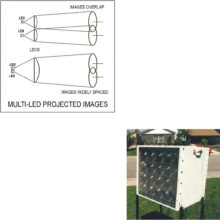
illustrated
in figure
7d, a single
lens should not be used
with multiple light sources. As
shown in the
illustration,
two light sources placed
side by in front of a single
lens will launch two spots
of light,
spaced
widely apart. Only one of
the spots would hit
the distant receiver. This
mode may be
desirable
in very rare situations, but
for most long range systems,
only one spot of light needs to
be
launched.
Adding more light sources in
front and a single lens
would not increase the
amount of
light
sent to a light receiver.
As
illustrated in figure
7d, a much
more
efficient
method to send more light to
a
distant
receiver is to use multiple
LEDs,
each
with its own lens.
The multi-source
array
will appear as a single light
source
with
an intensity of XP where X is
the
number
of lenses in the array and P is
the
light
power launched by a single
LED/lens
section.
A picture of an actual
working
unit
using such a method is shown
in
figure
7e below.
The unit uses 20
separate
LEDs
and 20 Fresnel lenses.
The
system demonstrated a range of six
miles
when transmitting voice
audio
information.
Transmitter systems should
consider
making some
compromises
between
a large number of
smaller
Figure
7d
LED/lenses
that will be easier to aim at
a
distant
transmitter and a system that
has fewer lenses
but
is harder to point at a distant
receiver. If power
consumption
is a concern, the system
with fewer
LEDs
should be used. Consider the
examples below.
Let's
consider two transmitter
enclosures. Each
enclosure
has the same surface
area on which to
install
lenses. One system used a
single large lens and
the
second used multiple lenses.
Suppose one system
uses
4 LEDs with 3.5" lenses
(49 sq. inches)
that
when
combined formed a 0.4 watt
source with a
divergence
angle of 1.0 degrees.
Now
let's suppose the second
system uses a single
Figure
7e
LED
with a 7" lens (also 49
square inches) which
yields
a combined power level of
0.1 watts but a divergence
angle of 0.5 degrees. As
seen from the
vantage
point of a distant light
receiver, the two systems
would appear to have the
same intensity
Figure
7e.
Page
62
of 68
Optical
Through-the-Air Communications Handbook
-David A. Johnson, PE
One
system launches more power
but spreads the light
over a wider area while
the other launches
less
power but points more of it
at the target. The effect is
the same. From a power
consumption
standpoint,
the single LED system
would be obviously much more
efficient. But, the unit
with
multiple
light sources and lenses
would be easier to aim at
the distant receiver.
Wide
Area Light
Transmitters
In
some applications the
challenge is not to send the
modulated light to some
distant receiver,
whose
position is fixed, but to
send the light in a wide
pattern, so either multiple
receivers or a
receiver
whose position changes, can receive
the information. Cordless audio
headsets, VCR and
TV
remote controllers and some cordless
keyboards all rely on either
a direct link or in a
indirect
diffuse
reflective link between the
light transmitter and the
receiver. The indirect paths
would rely
on
reflections off of walls.
Many of the light receiver
and transmitter techniques discussed
above
could
be used for wide area
communications. However, keep in
mind that to cover a wider
area the
distance
between the light
transmitter and the receiver
would have to be shorter
than a narrow beam
link.
Since the light being
transmitted is spread out,
less of it would make its
way to the receiver.
But,
it would be possible to use large
arrays of light emitting
diodes or some other light
sources so a
large
area can be bathed with lots of
modulated light. If only
short ranges are needed, one
light
source
can be used in conjunction with a
light detector as long as
the detector had a wide
acceptance
angle.
To achieve the widest
acceptance angle, a naked silicon
PIN photodiode works fine.
Some
large
1cm x 1cm detectors work great
for receiving the 40KHz
signals from optical TV
remote
control
devices. When these large
area detectors are used with
a quality receiver circuit, as
was
discussed
in the receiver circuit
section, a receiver can be designed to be
at least a hundred times
more
sensitive than conventional
light receiver circuits
often used in VCRs. The
increased
sensitivity
means, when used in a direct
link mode, the normal
operating distance can be
increased
by
a factor of ten. If your
typical VCR remote normally
has a 50 foot range, with
the receiver
changes,
the distance could be increased to 500
feet.
Wide
Area Information Broadcasting
If
you increase the scale of
the above methods, some
interesting concepts emerge. For
many years I
attempted
to get some communications companies
interested in the idea of
optical information
broadcast
stations. The idea was to
transmit high speed digital
data (up to 1Gigabit per second)
from
many
transmitting towers scattered
around a large metropolitan
area. Each tower might have
an
effective
radius of 5 miles in all
directions. Such a wide area
would mean only 4 towers
would be
needed
to cover an area of 400 square
miles. Since an optical broadcasting
system and a radio
broadcasting
system could coexist on the
same tower, many new
towers would not have to
be
erected.
Preexisting radio towers
could be used. The light
transmitters would also not
require any
FCC
licenses. So far, no federal agency
has been assigned the task
of regulating optical
communications.
The
light being transmitted from
the towers could originate
from arrays of powerful lasers.
Optical
fiber
cables could carry the
light from the ground
based light emitters to the
top of the towers.
Since
the
laser sources would emit
light with very narrow
wave lengths, the matching
light receivers
could
use equally narrow optical
filters to select only certain laser
colors or wavelengths.
This
technique
is called wavelength division
multiplexing and has been
used for many years
in
communications
systems using optical fibers.
The technique could be so
selective that the
number
of
different light channels
that could be transmitted and
received could number in the
hundreds.
Using
such an optical approach, the
data rate from each optical
transmitter could exceed 100
billion
Page
63
of 68
Optical
Through-the-Air Communications Handbook
-David A. Johnson, PE
bits
per second. Such a data rate is far
more than possible with
communications systems using
transmission
cables.
The
main objection potential
investors had for my idea
were the communications
interruptions from
bad
weather. It is true that
during some heavy snow
storms and thick fog
conditions the reception
of
the
transmitted light signals
could be blocked. But,
overall I felt that people
subscribing to such a
service
could tolerate a few
interruptions each year. In spite of my
arguments, I was not able to
find
any
investors. So, It is hoped that
someone reading this might
someday consider the idea and
make
it
a commercial success.
Page
64
of 68
Optical
Through-the-Air Communications Handbook
-David A. Johnson, PE
Figure
7a
Page
65
of 68
Optical
Through-the-Air Communications Handbook
-David A. Johnson, PE
Page
66
of 68
Optical
Through-the-Air Communications Handbook
-David A. Johnson, PE
Figure
7b
Table of Contents:
- LIGHT THEORY:The Spectrum, Human Eye Response, Silicon Detector Response
- LIGHT DETECTORS:The Silicon PIN Photodiode, Active Area, Response Time
- LIGHT EMITTERS:Light Emitting Diodes (LEDs), Solid State Semiconductor Lasers
- LIGHT SYSTEMS CONFIGURATIONS:Opposed Configuration, Diffuse Reflective Configuration
- LIGHT PROCESSING THEORY:Lenses as Antennas, Light Collimators and Collectors
- OPTICAL RECEIVER CIRCUITS:Current to Voltage Converter Circuits, Post Signal Amplifiers
- OPTICAL TRANSMITTER CIRCUITS:Audio Amplifier with Filters, Pulsed Light Emitters