 |

Chapter
Two
LIGHT
DETECTORS
What
Does a Light Detector
Do?
In
radio, the information that
is to be transmitted to a distant
receiver is placed on a high
frequency
alternating
current that acts as a
carrier for the information.
To convey the information,
the carrier
signal
must be modulated in some
fashion. Most radio systems
either vary the amplitude
(amplitude
modulation,
AM) or the frequency (frequency
modulation, FM) of the
carrier. To extract
the
information
from the carrier at the
receiver end, some kind of
detector circuit must be
used.
In
optical communications a light source
forms the carrier and must
also be modulated to transmit
information.
Virtually all present optical
communications systems modulate the
intensity of the
light
source. Usually the transmitter
simply turns the light
source on and off. To decode
the
information
from the light pulses, some
type of light detector must
be employed. The detector's
job
is
to convert the light
signals, collected at the
receiver, into electrical
signals. The electrical
signals
produced
by the detector's optical energy to
electrical energy conversion
are much easier to
demodulate
than pure light
signals.
As
discussed in the section on
light theory, although light
is a form of energy, it is the
intensity or
power
of the light that determines
its strength. Therefore, the
real job of the light
detector is to
convert
light power into electrical
power, independent of the
energy of the transmitted
light pulses.
This
relationship also implies that
the conversion is independent of
the duration of the light
pulses
used.
This is an important concept and is
taken advantaged of in many of the
systems that follow.
The
Silicon PIN Photodiode
Although
you may be aware of many
kinds of light detectors, such as a
"photo transistor",
"photo
cells"
and "photo resistors", there
are only a few devices that
are practical for
through-the-air optical
communications.
Many circuits that have
been published in various magazines,
have specified
"photo
transistors" as the main
light detector. Although
these circuits worked after
a fashion, they
could
have functioned much better
if the design had used a different
detector. From the list of
likely
detectors,
only the silicon "PIN"
photodiode has the speed,
sensitivity and low cost to be a
practical
detector.
For this reason virtually
all of the detector circuits
described in this book will
call for a
PIN
photodiode.
As
the letters PNP and NPN
designate the kind of
semiconductor materials used to
form transistors,
the
"I" in the "PIN" photodiode
indicates that the device is
made from "P" and "N"
semiconductor
layers
with a middle intrinsic or
insulator layer.
Most
PIN photodiodes are made
from silicon and as shown on
Figure
2a, have
specific response
curves.
Look carefully at the curve.
Note that the device is
most sensitive to the near
infrared
wavelengths
at about 900 nanometers. Also
notice that the device's
response falls off
sharply
beyond
1000 nanometers, but has a
more gradual slope toward
the shorter wavelengths,
including
the
entire visible portion of
the spectrum. In addition,
note that the device's
response drops to about
Page
14
of 68
Optical
Through-the-Air Communications Handbook
-David A. Johnson, PE
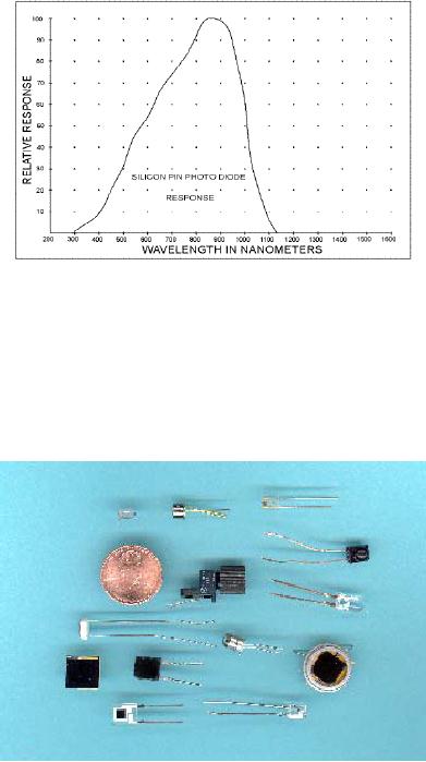
½
its peak at the visible red
wavelength
(640
nanometers). It should therefore
be
obvious
that if you want to maximize
the
device's
conversion efficiency you
should
choose
an information transmitter
light
source
which closely matches the
peak of
the
silicon PIN photodiode's
response.
Fortunately,
most IR light emitting
diodes
(LEDs)
and infrared lasers do indeed
emit
light
at or near the 900nm peak,
making
them
ideal optical
transmitters of
information.
Figure
2a
The
PIN photo detector behaves
very much like a small
solar cell or solar battery
that converts light
energy
into electrical energy. Like
solar cells, the PIN
photodiode will produce a voltage
(about
0.5v)
in response to light and will also
generate a current proportional to
the intensity of the
light
striking
it. However, this unbiased
current sourcing mode, or "photovoltaic"
mode, is seldom used
in
through-the-air communications since it is
less efficient and is slow in
responding to short
light
flashes.
The most common
configuration is the "reversed
biased" or "photoconductive"
scheme.
In
the reversed biased mode, the
PIN
detector
is biased by an external
direct
current
power supply ranging from a
few
volts
to as high as 50 volts. When
biased,
the
device behaves as a leaky diode
whose
leakage
current is dependent on the
intensity
of the light striking the
device's
active
area. It is important to note
that the
intensity
of a light source is defined in
terms
of power, not energy.
When
detecting
infrared light at
its 900
nanometer
peak response point, a
typical
PIN
diode will leak about one milliamp
of
current
for every two milliwatts of
light
Samples
of Detectors
power
striking it (50%
efficiency).
For
most devices this relationship is
linear over a 120db (1 million to
one) span, ranging from
tens
of
milliwatts to nanowatts. Of course
wavelengths other than the
ideal 900 nanometer peak will
not
be
converted with the same
50% efficiency. If a visible red
light source were used the
light to
current
efficiency would drop to
only 25%.
The
current output for light
power input relationship is
the most important
characteristic of the
PIN
photodiode.
The relationship helps to
define the needs of a
communications system that
requires a
signal
to be transmitted over a certain
distance. By knowing how much
light power a
detector
circuit
requires, a communications system can be
designed with the correct
optical components.
Page
15
of 68
Optical
Through-the-Air Communications Handbook
-David A. Johnson, PE
The
light power to electrical
current relationship also implies
that the conversion is
independent of
the
duration of any light pulse.
As long as the detector is
fast enough, it will produce
the same
amount
of current whether the light
pulse lasts one second or one nanosecond.
Later, in the section
on
light transmitter circuits, we will take
advantage of this relationship by using
short light pulses
that
don't consume a large amount
of electrical power. Also, in
the section on light
receivers we will
use
some unique detector
circuits that are designed
to be sensitive only to the
short light pulses
being
transmitted. Such schemes
provide improvements over
many existing commercially
made
systems
and enable simple components to produce
superior results.
InGaAs
PIN Diode
Silicon
is not the only material
from which
to
make a solid-state light detector.
Other
photodiodes
made from Gallium and
Indium
semiconductors work well
at
longer
infrared wavelengths than
silicon
devices.
These devices have been used
for
many
years
in
optical
fiber
communications
systems, which rely on
longer
wavelengths. Glass optical
fibers
operate
more efficiently at these
longer
wavelengths.
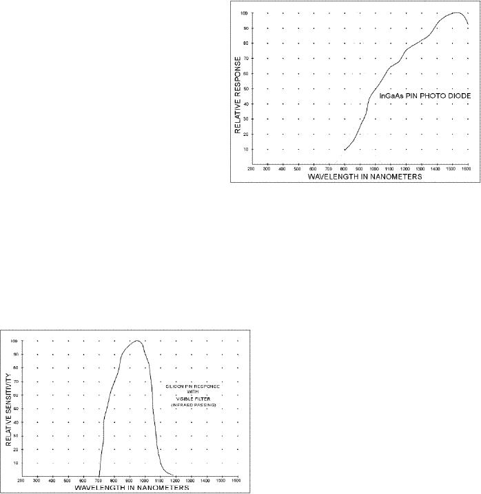
The curve shown below
is
the
typical response for this
device but
peak
can be shifted slightly as needed.
As
shown
in the curve (Figure
2a-1), an
InGaAs
photodiode's response
includes
Figure
2a-1
only
some of the wavelengths that
a
silicon
photodiode covers. However,
most of the devices made are
designed for optical
fiber
communications
and therefore have very
small active areas. They
are also much more
expensive.
Still,
as the technology improves,
perhaps these devices will find
their way into the hands
of
experimenters.
Typical
PIN Diode
Specifications
Package
PIN
silicon photodiodes come in all
sizes
and
shapes. Some commercial
diodes are
packaged
in special infrared
(IR)
transparent
plastic. The plastic blocks
most
of
the visible wavelengths
while allowing
the
IR light to pass (see
Figure
2b).
The
plastic
appears to be a deep purple
color
when
seen by our eyes but it is
nearly
crystal
clear to infrared light.
Some of
these
packages also place a small
plastic
lens
in front of the detector's active
area to
collect
more light. As long as
the
Figure
2b
modulated
light being detected is also
IR
either
the filtered or the
unfiltered devices will work. However, if
you use a light source that
emits
Page
16
of 68
Optical
Through-the-Air Communications Handbook
-David A. Johnson, PE
visible
light you must
use
an unfiltered PIN device. In
the section on light
receiver circuits there
is
a
discussion on why the filtered
PIN diodes are usually
unnecessary when the proper
detector circuit
is
used.
Active
Area
There
will usually be an active area
specification for PIN
photodiodes. This corresponds to the
size
of
the actual light sensitive
region, independent of the
package size. PINs with
large active areas
will
capture more light but will
always be slower than
smaller devices and will also produce
more
noise.
However, if a small device
contains an attached lens it will often
collect as much light as
a
much
larger device without a
lens. But, the devices with
attached lenses will collect light
over
narrower
incident angles (acceptance angle).
Flat surface devices are
usually used if light must
be
detected
over a wide area. For
most applications either
style will work. For high
speed applications
a
device with a small active
area is always recommended.
However, there is a tradeoff
between
device
speed and the active area.
For most long-range
applications, where a large
light collecting
lens
is needed, a large area
device should be used to
keep the acceptance angle
from being too
small.
Small acceptance angles can make it
nearly impossible to point
the receiver in the
right
direction
to collect the light from
the distant
transmitter.
Response
Time
All
PIN photodiodes will have a
response time rating that is
usually listed in nanoseconds.
The
rating
defines the time the
device needs to react to a short
pulse of light. The smaller
the number,
the
faster the device. Sometimes
you will see both a rise
time and a full-time rating.
Usually, the
fall-time
will be slightly longer than
the rise time. Large area
devices will always be slower and
have
longer response times. To be
practical for most
applications, the device
should have a
response
time
less than 500 nanoseconds. However,
even devices with response
times greater than tens of
microseconds
may still be useful for
some applications that rely
on light pulses a few
milliseconds
long.
A slow device will respond to a
short
light pulse by producing a
signal
that
lasts much longer than the
actual light
pulse.
It will also have an apparent
lower
conversion
efficiency. The
detector
should
have a response time that
is
smaller
than the maximum needed
for the
detection
of the modulated light
source
(see
section on system designs). As an
example,
if the light pulse to be
detected
lasts
1 microsecond then the PIN
used
should
have a response time less
than ½
microsecond.
The response time may
also
be
linked to a specific reverse
bias
voltage.
All devices will respond faster
Figure
2b-1
when
a higher bias voltage is
used. Some
device
specifications will show a curve of
response times as a function of
bias voltage. To play
it
safe,
you should use the
response time that is
associated with a bias
voltage of only a few volts
on
the
time vs. voltage curve. If
you are interested in
measuring a PIN diode's
response time, there
are
some
methods described in the
section "Component and System
Testing".
Page
17
of 68
Optical
Through-the-Air Communications Handbook
-David A. Johnson, PE
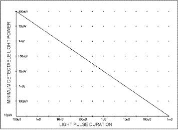
If
you plot a curve of the
minimum detectable light power,
using a photodiode, and the
light pulse
width
being detected, you generate
the curve shown below.
The curve implies that
for a very short
100
picoseconds light pulse, you will
need at least 100 microwatts of light
power to be detectable.
But,
if the light pulses last
longer than 1 millisecond
were used, you could detect
light pulses down
to
about 10 picowatts. This is a
handy curve to have, when
you are designing an
optical
communications
system. It will give you a
ballpark idea of how much
light you will need based
on
the
light pulse widths being
transmitted.
Capacitance
When
choosing a suitable light
detector from a manufacturer,
their data sheets may also
list a total
capacitance
rating for the PIN
device. It is usually listed in
Picofarads. There is a direct
correlation
between
the active area and the
total capacitance, which has an
effect on the device's
speed.
However,
the capacitance is not a
fixed value. The capacitance will
decrease with higher
reverse
bias
voltages. As an example, a typical
PIN device with a one square
millimeter active area
might
have
a capacitance of 30 Pico farads at bias
voltage of zero but will
decrease to only 6 Pico farads at
12
volts. Large area devices will
always have a larger capacitance and will
therefore be slower
than
small
area devices. If you have
nothing else to go on, pick
a device with the lowest
capacitance, if
you
are detecting short light
pulses.
Dark
Current
All
PIN diodes have dark
current ratings. The rating
corresponds to the residual leakage
current
through
the device, in the reversed
biased mode, when the
device is in complete darkness.
This
leakage
current is usually small and is
typically measured in nanoamps, even
for large area
devices.
As
you would expect, large
area devices will have larger
dark currents than small
devices.
However,
by using the one of the
detector circuit discussed in
the section on light
receivers, even
large
leakage levels will have
little effect on the
detection of weak
signals.
Noise
Figure
When
reviewing PIN diode specifications
you may also come across a noise
figure listing. The
units
chosen
are usually "watts per
square root of hertz". Sometimes
the listing will be under
the heading
of
"NEP" that stands for
"noise equivalent power". I
suggest you ignore the
specification. It has
little
meaning for most
through-the-air applications that will
always have to contend with
some
ambient
light. Also, many of the
detector circuits recommended in
this book will reject much
of the
noise
produced by the detector.
For a more detailed
discussion of detector noise please
refer to the
section
on detector noise below.
Other
Light Detectors
Photo
Transistor
One
of the most popular light
detectors is the photo transistor.
They are cheap, readily
available and
have
been used in many published
communications circuits. But as I
have indicated above, the
PIN
Page
18
of 68
Optical
Through-the-Air Communications Handbook
-David A. Johnson, PE
photodiode
is still a much better
choice if you want systems
with better
performance.
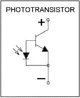
As shown in Figure
2b-1, a
phototransistor is a silicon
photodiode
connected to the base-emitter terminals
of a silicon
transistor.
Since the phototransistor it is made of
silicon, it has a
similar
response
curve as a standard silicon PIN
photodiode. The photodiode
is
connected
directly to the transistor, it is
not reversed biased and
operates
in a photovoltaic mode. The current
produced by the
photodiode
is routed to the transistor
that provides a sizable
current
gain.
This amplification gives the
photo transistor much more
light
sensitivity
than a standard PIN diode.
But, with the gain
comes a price.
Figure
2b-1
The
photodiode/transistor connection
dramatically slows down
the
otherwise
fast response time of the
diode inside. Most phototransistors will
have response times
measured
in tens of microseconds, which is some
100 times slower than
similar PIN diodes.
Such
slow
speeds reduce the usefulness of
the device in most
communications systems. They also
have
the
disadvantage of having small active
areas and high noise levels. You will
often find them
being
used
for simple light reflector
and detector applications that do
not rely on fast light
pulses. But,
overall,
they are a poor substitute
for a good PIN diode when
connected to well designed
receiver
circuit.
Avalanche
Photodiode
Although
the silicon PIN detector is
the most universal device
for nearly all optical
communications
applications,
there are a few other
devices worth mentioning. Once
such device is an "APD"
or
avalanche
photodiode. An APD is a special light
detecting diode that is constructed in
much the
same
way as a PIN photodiode.
Unlike a PIN diode, that
only needs a bias of a few
volts to function
properly,
an APD is biased with
voltages up to 150 volts. When
light strikes the device it
leaks
current
in much the same way as a
typical PIN diode, but at
much higher levels. Unlike a
PIN diode
that
may produce only one
microamp of current for two
microwatts of light, an APD can
leak as
much
as 100 microamps for each
microwatt (x100 gain). This
gain factor is very dependent on
the
bias
voltage used and the APDs
operating temperature. Some systems take
advantage of these
relationships
and vary the bias voltage to
produce the desired gain.
When used with narrow
optical
band
pass filters and laser light
sources APDs could allow a
through-the-air system to have a
much
higher
light sensitivities and thus
longer ranges than might
otherwise be possible with a
standard
PIN
device. However, in systems that
use LEDs, the additional
noise produced by the ambient
light
focused
onto the device cancels much
of the gain advantage the
APD might have had over a
PIN.
Also,
most commercial APDs have
very small active areas,
making them very unpopular
for
through-the-air
applications. They are also
typically 20 times more
expensive than a good
PIN
photodiode.
Finally, the high bias
voltage requirement and the
temperature sensitivity of the
APD
causes
the detector circuit to be
much more complicated that
those needed with a PIN.
Still, as the
technology
improves, low cost APDs with
large active areas may
become available.
Page
19
of 68
Optical
Through-the-Air Communications Handbook
-David A. Johnson, PE
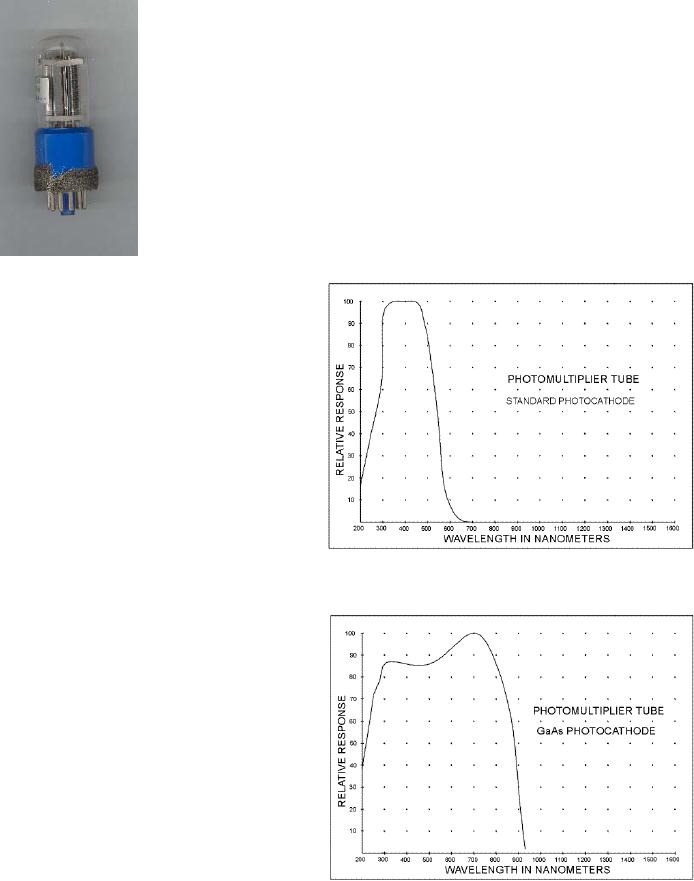
Photo
Multiplier Tube
An
older device that is still
being used today to detect
very weak light
levels
is the photo multiplier tube
(PMT). The photo multiplier
is a
vacuum
tube that operates somewhat
like an avalanche
photodiode.
Light
striking a special material called a
"photo cathode" forces
electrons
to
be produced. A high voltage
bias between the cathode and a
nearby
anode
plate accelerates the
electrons toward the anode.
The high speed
electrons
striking the first anode
causes another material
coated on the
anode
to produce even more
electrons. Those electrons
are then
accelerated
toward a second anode. The
process is repeated with
perhaps
as
many as ten stages. By the
time the electrons emerge
from the last
anode,
the photo current that
results may be 10,000 times greater
than
the
current that might have
been produced by a PIN
detector.
Photo
Multiplier Tub
This
high gain makes the
PMT the most
light
sensitive device known. They
are
also
fast. Some will have
response times
approaching
good PIN diodes. However,
the
PMT has several drawbacks.
It is a
physically
large device. Also, since it
is
made
of glass, it is much more fragile
than
a
solid state detector. Also,
the high
voltage
bias, that is required,
makes the
supporting
circuits
much
more
complicated.
In addition, because of
the
very
high gains available, stray
light must
be
kept to very low
levels.
Figure
2c
The
ambient light associated
with a
through-the-air
communications system
would
cause some serious problems.
You
would
have to use a laser light source
with
very
narrow optical band pass
filter to take
advantage
of a PMT. As shown in figure
2c, most
PMTs are better suited
to
detecting
visible and ultraviolet light
than
infrared
wavelengths. Only some of
the
latest
devices have useful gains in the
near
infrared.
(see Figure
2c-1.) Finally,
PMTs
are
usually very expensive.
Still, PMTs do
have
rather large active areas.
If used with
visible
wavelength lasers and
narrow
Figure
2c-1
optical
filters, a PMTs large active
area could allow a receiver
system to use a very large
light
collecting
lens. If optimized, such a
system could yield a very
long range. But overall, a
PMTs
disadvantages
far outweigh their
advantages in most
applications.
Page
20
of 68
Optical
Through-the-Air Communications Handbook
-David A. Johnson, PE
Optical
Heterodyning
Another
detector scheme, that has
already been demonstrated in the
laboratory and may someday be
available
to the experimenter, is "optical
heterodyning". The scheme doesn't
actually use a new
detector
but rather a new way of
processing the light with an
existing detector. Students
of
electronics
should be familiar with the
classical super-heterodyne technique
used in most radio
receivers.
In brief, this method mixes
the frequencies from the
incoming radio signal with
another
fixed
local oscillator frequency.
The result is both a sum and
difference family of frequencies
that
can
be more easily amplified and
used to separate the desired
signal from the background
noise and
interference.
This same principle has
now been applied in the
realm of optical
frequencies.
To
make the optical heterodyne
concept work, special lasers
must be used that have
been carefully
constructed
to emit light of very high
purity. The light from
these lasers is very nearly
one single
wavelength
of light. When the light
from two of these lasers
that emit light of slightly
different
wavelengths,
is focused onto a detector,
the detector's output frequency
corresponds to a sum and
difference
of the two wavelengths. In
practice, the light from a
nearby laser produces light with
a
slightly
different wavelength than
the distant transmitter
laser. As in the radio
technique, optical
heterodyning
should allow very weak
signals to be processed more
easily and should also
permit
many
more distinct wavelengths of
light to be transmitted without
interference. A single
light
detector
could then be used in
conjunction with multiple laser sources.
This technique is
often
referred
to as "wavelength division multiplexing"
and could allow a single
receiver system to select
one
color "channel" from among
several thousand channels
transmitted. But, for the
average
experimenter,
such techniques are just
too complicated.
Future
Detectors
Experimental
research in optical computers
may lead to some useful
light detectors at some time
in
the
future. Most likely, a
device will be developed that will
amplify light somewhat like
a transistor
amplifies
current. Such a device would
use some kind of external
light that would be
modulated by
the
incoming light. Perhaps
light emitted from a
constant source would be sent through
the device at
one
angle and would be modulated by
the much weaker light
striking the device at
another angle.
Since
these devices would use only
light to amplify the
incoming light, without an
optical to
electrical
conversion, they should be
very fast and might have
large active areas. Such
detectors
may
eventually allow individual
photons to be detected, even at high
modulation rates. If
these
advanced
detectors do become available, then
many optical through-the-air
communications
systems
could be designed for much
longer ranges than now
possible. Perhaps the combination
of
higher
power light sources and more
sensitive light detectors will allow a
future system to be
extended
by a factor of 100 over what is
now possible.
In
addition to the above "all
optical" detector there may
be other kinds of detectors developed
that
work
on completely different concepts. Some
experiments on some special materials
suggest that an
opto-magnetic
device might make a nice
detector. Such a device produces a
magnetic field change
in
response to incident light. A
coil wrapped around the
material might be used to detect
the small
change
in the field and thus might
allow small light levels to
be detected. As electro-optics
science
grows
I expect many new and useful
devices will become available to the
experimenter.
Detector
Noise
Unlike
fiber optic communications,
through-the-air systems collect
additional light from
the
environment.
Light from the sun, street
lights, car head lights and
even the moon can all be
focused
Page
21
of 68
Optical
Through-the-Air Communications Handbook
-David A. Johnson, PE
onto
the detector. The stray
light competes with the
modulated light from the
distant transmitter. If
the
environmental light is sufficiently
strong it can interfere with
light from the light
transmitter. As
indicated
above, the light striking
the detector produces a DC current
proportional to the
light
intensity.
But, within the DC signal
produced there is also some broadband AC
noise components.
The
noise produces random electrical signal
fluctuations. The background
static you often hear
on
an
AM radio when tuned between
stations is one example of noise.
Fortunately, the magnitude
of
the
AC noise seen in an optical receiver is
small but it can still be
high enough to cause
problems.
The
noise has the effect of
reducing the sensitivity of
the detector, during high
ambient light
conditions.
As will be discussed in the section on
light receiver circuits,
some tricks can be
employed
to lessen the amount of noise
that would otherwise be
produced at the detector
from
ambient
light. But, as long as there
is extra light focused onto
a detector there will always be
noise.
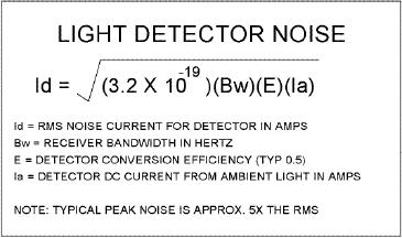
The
equation shown in
Figure
2d
describes
how the detector noise
varies
with
ambient light. The
relationship
follows
a square root function. That
means
if
the ambient light level
increases by a
factor
of four, the noise produced at
the
detector
only doubles. This
characteristic
both
helps and hurts a light
receiver
circuit,
depending on whether the
system
is
being used during the
light of day or
during
the dark of night. The
equation
Figure
2d
predicts
that for high ambient
daytime
conditions,
you will have to dramatically reduce
the amount of ambient light
striking the detector
in
order
to see a significant reduction in
the amount of noise produced at
the detector circuit.
The
above equation also describes that
under dark nighttime
conditions, the stray light
has to
dramatically
increase in order to produce a
sizable elevation in noise. If the
system must work
during
both day and night, it will
have to contend with the
worst daytime noise
conditions.
Conversely,
some light receivers could
take advantage of the low stray
light conditions found
at
night
and produce a communications system
with a much longer range
than would be
otherwise
possible
if it were used during
daylight.
Minimum
Detectable Light Levels
The
weakest modulated light signal
that can be detected by a typical
PIN diode will be dependent
on
several factors. The most
important factor is the noise
produced by the detector. As
discussed
above,
the detector noise is very dependent on
the amount of extra light
striking the detector.
For
most
medium speed applications,
the weakest modulated light
signal that can be detected is
about
0.1
nanowatts. But, such a
sensitivity can only be achieved
under very dark conditions,
when
virtually
no stray light is focused
onto the detector. In many
daytime conditions the
ambient light
level
may become high enough to
reduce the minimum detectable signal to
about 10 nanowatts.
However,
to insure a good communications link
you should plan on
collecting enough light so
the
signal
of interest, coming from the
distant transmitter, is at least 10 times
higher in amplitude
than
the
noise signal. This rule-of-thumb is
often referred to as a minimum 20db
signal to noise ratio
(SNR).
Page
22
of 68
Optical
Through-the-Air Communications Handbook
-David A. Johnson,
PE
Table of Contents:
- LIGHT THEORY:The Spectrum, Human Eye Response, Silicon Detector Response
- LIGHT DETECTORS:The Silicon PIN Photodiode, Active Area, Response Time
- LIGHT EMITTERS:Light Emitting Diodes (LEDs), Solid State Semiconductor Lasers
- LIGHT SYSTEMS CONFIGURATIONS:Opposed Configuration, Diffuse Reflective Configuration
- LIGHT PROCESSING THEORY:Lenses as Antennas, Light Collimators and Collectors
- OPTICAL RECEIVER CIRCUITS:Current to Voltage Converter Circuits, Post Signal Amplifiers
- OPTICAL TRANSMITTER CIRCUITS:Audio Amplifier with Filters, Pulsed Light Emitters