 |
[IP
Telephony Cookbook] /
IP Telephony Scenarios
IP
Telephony Scenarios >
3
>
3.1
Introduction
Using
the background technological terminology
defined in the previous
chapter, this chapter
describes
the most interesting
scenarios in building an IP Telephony
infrastructure.The following
scenarios
address topics with
increasing complexity (from a
long-distance least-cost
routing
scenario
to a fully-integrated IP Telephony - videoconferencing
one).The aim of this chapter is
to
provide
the reader with both an
overview of each scenario
and motivation for deploying
them.
Each
scenario is analysed from
the user-needs point of view
and is described
architecturally,
giving
an example of an implementation.
>
3.2
Scenario 1: Long-distance least-cost
routing
This
scenario is likely to be adopted by
enterprises with high-cost call
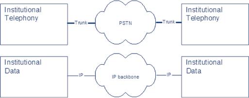
volumes.Traditionally,
separate
links have been used for
transferring voice and data
between two sites (see
Figure 3.1),
thus
making it simple to achieve a reduction in
costs by establishing accounts
with a lower-cost
long-distance
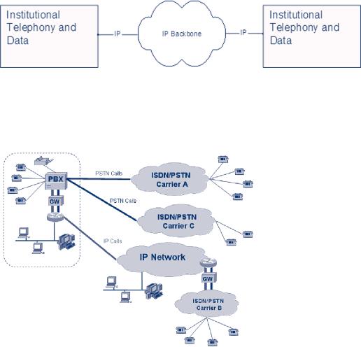
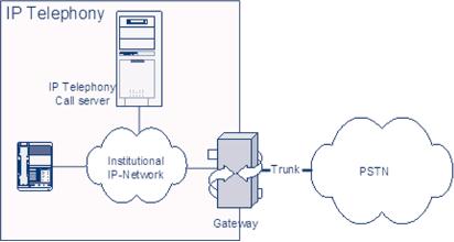
carrier.Voice over IP offers an
alternative solution for this
kind of problem; existing
enterprise
data networks (using the IP protocol)
may be used to carry
long-distance voice traffic
to
certain destinations, thus
lowering the total costs
(see Figure 3.2). A
combination of a lower-
cost,
long-distance carrier and Voice
over IP voice-data integration is seen as
the most cost-
effective
solution in this area.This requires
the routing of calls to the
lowest-cost network,
depending
on the time of day and
destination, and it is referred to as
Least-Cost Routing
(LCR).
In
order to achieve greater
savings, it routes calls to
destinations by re-dialling them through
the
lowest
cost alternative carrier/terminator
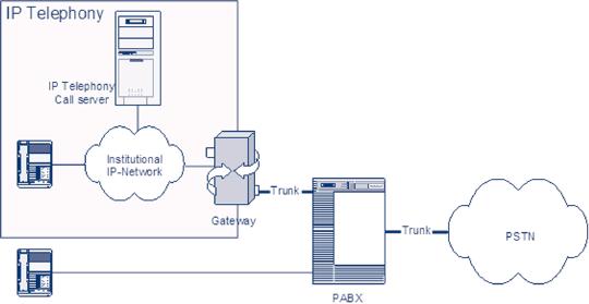
available. A basic scenario's
architecture (depicted in
Figure
3.3) is able to handle all
calls originating from the
enterprise network. Elements
needed to
deploy
this scenario are: terminals
(both IP and PSTN) and the
necessary gateways to route
the
call
from the IP network to the
ISDN/PSTN/GSM and vice versa.
Other elements like
MCUs
or
servers may be present, but
are not required.
Figure
3.1 Traditional separation of data
and telephony between
locations
P.52
[IP
Telephony Cookbook] /
IP Telephony Scenarios
Figure
3.2 Integration of data and
telephony between
locations
A
hybrid solution, including both traditional
processing of calls over
PSTN/ISDN and additional
IP
Telephony parts, results in
this detailed
architecture.
Figure3.3
Least-cost routing
architecture
The
features that a least-cost
routing architecture may
provide can be summarised
as:
-
call routing by time of day
and day of the week,
allowing selection of the
best rates for
specific
time
periods;
-
call routing by destination,
allowing selection of the
best rates depending on the
destination of
the
call;
-
number modification, allowing dial-string manipulation
of the original number dialled,
to
facilitate
prefix-based routing;
-
class of service management,
allowing management of individual
extensions with
differentiated
class
of service, to give that
higher level of service to
users who need
it.
>
3.2.1
Least-cost routing - an example of an
implementation
A
company with head-quarters
offices and multiple-branch office
sites in Europe makes
daily
long-distance
calls to contact customers
located all over the
world. Since many telephone
carriers
provide
cheap telephone rates
depending on geographic areas,
the competitive telephone
market
may
be used to reduce communication
costs. A first solution would require
the maintenance of an
up-to-date
table, based on the savings
depending on the time of day
and destination.The
problems
arising from this solution in
the maintenance and
distribution of this table to
the
employees
are evident. Moreover, it is certain
that not every employee
will remember to dial
the
P.53
[IP
Telephony Cookbook] /
IP Telephony Scenarios
extra
digits for each appropriate
prefix, both because it is time-consuming
and, as a result of
negligence.
Therefore,
an engineering process is needed to
keep the costs low.
Least-cost routing is
the
solution
to these kinds of problems,
because it allows the
telephone system to automatically
route
the
long-distance call to the
most economical telephony
carrier/network, saving money on
the
long-distance
bill and reducing the
employee's effort in making calls.
In
order to put such solution in place,
the company needs to deploy
a set of gateways in
the
locations
where branch offices are
located, to take advantage of
the integration of data
and
telephony
links between locations as depicted in
Figure 3.2.This can result in
savings from both
calls
located in the area of the
branch offices, as well as
office-to-office calls, taking advantage
of
the
data network connecting the
company's sites. Note that
in this case, a distributed routing
table
has
to be implemented, in order to facilitate control by
the system administrator, who
may wish to
update
it anytime changes in long-distance rates
occur.
>
3.3.
Scenario 2: Alternatives to legacy PBX
systems
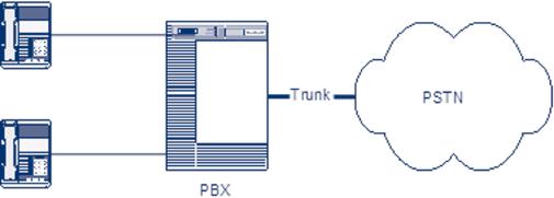
Traditionally,
institutions and companies are
equipped with a PBX on each
one of its sites.
Telephones
are wired to the PBX,
which supplies them with
power.The PBX handles
all
intelligence
and routes calls to the
PSTN over trunks (E1,T1, J1,
ISDN30, etc).
Figure
3.4 Legacy PBX which trunks
to the PSTN
One
of the most economically feasible
deployments of IP Telephony is currently is in
the area of
installing
voice over IP as a replacement
for inter-building PSTN
connections within
one
company,
or even, the complete
replacement of the PBX phone
system itself, along with
its
terminals.
This
chapter first describes the
scenarios in which IP phones
can be deployed in a
peer-to-peer
fashion
without additional control entities in
the network.This case is
only covered briefly
because
its practical use is
limited.
Then,
a more common scenario will be
described, where IP Telephony is introduced
into the
existing
telephony infrastructure.The legacy
PBX is still functional in this
scenario and voice
calls
can
be carried not only over
regular PSTN trunks, but also
over IP backbones.
P.54
[IP
Telephony Cookbook] /
IP Telephony Scenarios
The
last scenario describes the
total replacement of a PBX infrastructure
by IP Telephony
equipment.
>
3.3.1
Scenario 2a: IP Phones without a PBX
system
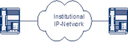
The
simplest case of IP Telephony is making a
point-to-point call between IP
Phones.To place a
call,
the calling party needs to
know the IP address of the
called party, or its DNS
entry.
Figure
3.5 IP Phone to IP Phone
without PBX
For
mission-critical cases, such as a
commercial company or an institutional
phone system, this is
an
awkward method. Moreover, it is not possible to
make a call to a regular
telephone within the
institution
or to the PSTN, because no
VoIP-to-PSTN gateway is available.
Also, common features
like
central address books, call
forwarding services, etc. are
harder to integrate with the
phone
terminal.
If the destination is unreachable,
nothing useful can be done
with the call,
like
redirecting
it to a voicemail service, etc.This setup is
therefore only recommended
for testing
purposes.
Call
setup is very simple, when
using either H.323, or SIP, or
any variations of these
protocols.
Since
the calling party directly enters
the IP address of the
destination, call initiation
signalling is
sent
directly to that IP address. If the
terminal is functional, it will process
the signalling and
the
called
party will be prompted to pick up
the phone.When that happens,
the call is setup, a
codec
is
negotiated and the voice
stream will start, until
signalling that terminates
the call is
exchanged.
>
3.3.2.
Scenario 2b: Integration of VoIP with legacy PBX
systems
This
scenario allows the
co-existence and intercommunication of
the institutional
conventional
telephony
network (conventional phones
connected to PBX) and the
local IP Telephony
network.The
scenario is suitable when
the local IP Telephony
network is constructed gradually
in
an
institution that already has a
conventional telephony
network.
In
a later stage, the
conventional telephony network
and the PBX can be
totally replaced by
the
IP
Telephony network, thus
converging to Scenario
2c.
For
example, in order to provide
for smooth transition, it might be
worthwhile to buy a
gateway
with
two ISDN PRI interfaces (or
just with one interface
and borrow the second
interface for
P.55
[IP
Telephony Cookbook] /
IP Telephony Scenarios
the
transition period). One interface is
connected to the PSTN and
the second one to the
PBX.
During
the transition period, a gateway also
performs call routing
between the PSTN and
the old
PBX
and vice versa, providing a smooth
transition.
This
chapter gives an overview of
options for interconnecting a PBX to a
Voice Gateway
(VoGW).These
options also apply to
Scenario 1. More technical
details for individual
interfaces
are
given in Chapter 4.
Figure
3.6 Integration of IP Telephony
with a legacy PBX
system
The
choice of a particular interface
between a PBX and a VoGW
depends on the
required
functionality,
availability of interconnection ports on both sides
and also on cost
constraints.
Interfaces
can be divided into analogue
and digital.The former include a
2-wire U-interface
with
a
subscriber loop and various
types of E&M interfaces.The latter
include an E1/CAS trunk
with
MFC-R2
signalling and ISDN with
DSS1 or QSIG signalling.
Giving technical details
about the
trunks
and interfaces mentioned above is
outside the scope of this
chapter Please refer to
Chapter
4
for further details. On the
other hand, technical people
who want to understand this
kind of
scenario
may benefit from a
discussion of the advantages
and shortcomings of
individual
interfaces,
which are summarised in the
following list:
-
Subscriber
loop -
suitable when conventional
phones should be connected directly to
VoGW
(Voice
GateWay) via an FXS
interface - an FXS interface
connects directly to a standard
telephone
and supplies ring, voltage,
and dial tone, but can
also be used for
PBX
interconnection.
A disadvantage is that when calling
inward towards the PBX, an
extension
number
can be dialled only as DTMF
(Dual-Tone Multi-Frequency) suffix,
after a call is
established
and is already accounted
for.This type of interface is
usually a low-cost solution;
-
E&M
interfaces - E&M
commonly stands for both Ear
and Mouth or recEive and
transMit.
It
allows extension dialling
before the conversation
begins. It requires a special
interface card for
the
PBX, but if the PBX is
already equipped with this
card, this can also be a
low-cost solution;
-
E1/CAS
trunk with MFC-R2 signalling
- CAS
(Channel Associated Signalling)
exists in
many
variants that operate over
analogue and digital
interfaces.The advantage of a
digital
interface
is its ability to transfer
the identification of the calling
party, which is important
for
detailed
accounting.This is the first digital solution
that was used, which
was later largely
P.56
[IP
Telephony Cookbook] /
IP Telephony Scenarios
replaced
by ISDN interfaces. It requires
special interface cards on both
sides of the
interconnection,
and it is a rather expensive
solution;
-
ISDN
with DSS1 signalling - In addition to
calling party identification,
supplementary
services
are available such as Call
Waiting, Do Not Disturb, etc. It
can be used with a
BRI
interface
(Basic Rate Interface, up to 2
simultaneous calls) or a PRI
interface (Primary
Rate
Interface,
up to 30 simultaneous calls).The
interface card is usually
already in place on modern
PBXs.The
PRI interface is economically preferable
when more than 8 channels
(4xBRI) are
required;
-
ISDN
with QSIG signalling - QSIG
signalling supports more supplementary
services, such
as
completion, Path replacements,
etc. However, QSIG uses
proprietary features of the
PBX
from
particular manufacturers and is
therefore suitable only for
corporate networks, where IP
Telephony
is used to interconnect PBXs in company
branches.
>
3.3.3.
Scenario 2c: full replacement of legacy
PBX systems
It
is only in greenfield situations,
when building a telephony
service from scratch, or
when an
existing
PBX is fully depreciated,
that IP Telephony can be
considered as a complete
replacement
alternative
to a traditional PBX.
Figure
3.7 IP Telephony fully-replacing
PBX
The
design of an IPBX system
involves a couple of
choices.
>
3.3.3.1
Intelligent vs. simple
terminals
IPBXs
can support terminals in two
ways: either through analogue
ports that support
analogue
terminals,
or through IP only.The latter implies
that the terminals are
intelligent devices,
including
an implementation of signalling functions.
Since intelligence in IP phones is
built-in
anyway,
these terminals are often
equipped with interactive
screens and other
sophisticated
functions.
As a result, the equipment is expensive
and requires the provision
of power, either
externally
or by Power-over-Ethernet. A feature that
most of these advanced
terminals support is
pass-through
of Ethernet packets, so that a single
wall outlet can be used
for both IP Telephony
and
computer data.
P.57
[IP
Telephony Cookbook] /
IP Telephony Scenarios
>
3.3.3.2
Signalling
Though
the choice among H.323,
SIP and proprietary protocols
seems a purely technical
one, it
has
implications on the interoperability with
future expansions, inter-department
trunking and
the
deployment of new advanced
features, like messaging,
etc. It is wise to require that a
supplier
complies
with at least one of the
open standards.
>
3.3.3.3.
Inter-department trunking
The
choice of a complete, IP-based
institutional voice architecture
does not automatically lead
to
a
specific solution for connecting
geographically-separated locations.The cookbook
examines the
options
for this case in the
`Least-Cost Routing'
Section.
The
inter-departmental architecture also
involves a choice of whether to
break out local calls
at
local
PSTN trunks, or to centralise all
PSTN trunking on one of the
locations of the
institution.
This
choice depends on the tariff
structure that the public
operator(s) offer for
centralised break
out,
as well as the volume of calls
that have a local public
destination as compared to
long-distance
publicly-
and privately- destined
calls.
>
3.3.3.4
Legacy functionality
Traditional
PBXs have the advantage
that long-recognised needs
have been incorporated in
their
functionality
through decades of development.These
important features need to be
implemented
by
the IP Telephony architecture as
well, if it is to become a competitive
solution.The most
elementary
of these are:
-
emergency call handling to
public emergency numbers
(911, 112 etc);
-
public dialling plan routing
(regular numbers, blocking/routing of
premium numbers etc);
-
integration with public wireless
telephony;
-
voice/data integration and call
distribution for call centre/help
desk department;
-
support for beeper
systems;
-
support for private wireless
telephony;
-
support for elevator
phones.
>
3.3.3.
Wireless VoIP
With
at least three manufacturers
currently presenting wireless IP
terminals that can use
IEEE
802.11b
(Wi-Fi) wireless data
communication, a new aspect
for VoIP is emerging. Where
DECT
has
a strong position in the wireless
PBX market, it can be expected
that institutions with
Wi-Fi
networks
in place, will want to reuse
this infrastructure for
their wireless telephony
network,
obtaining
similar consolidation advantages, as in the
fixed-IP Telephony case. Wireless IP
phones
are
equally as intelligent as their
fixed IP equivalents, but are different
on the Ethernet level.
The
usual
issues in wireless data communications
are battery autonomy, portability,
coverage, etc.
Current
developments show that
manufacturers of public network
mobile phones like GSM
are
planning
to include Wireless VoIP into
their terminals. This would
enable seamless roaming
from
P.58
[IP
Telephony Cookbook] /
IP Telephony Scenarios
public
mobile telephony networks to the
campus wireless environment, potentially
reducing costs
when
calling locally on campus.
>
3.3.3.6.
Issues
Since
the field of IPBXs is rapidly emerging,
many features that are
known in the traditional
PBXs
are quickly adopted.
Additionally, new issues
arise as data networks develop. An
example is
the
introduction of network access
control by IEEE 802.1X. This
standard forces equipment to
first
authenticate at a RADIUS server
before accessing the
network. All equipment on
802.1X-
enabled
network ports should be 802.1X-enabled as
well. With the adoption of
802.1X, the
vendors
are announcing terminals that
support this standard as
well.
A
similar situation holds true for
VLANs. In case a network administrator
chooses to put IP
telephones
in a different VLAN from PC (groups) and
the IP telephones are in
pass-through
configuration,
they should support VLAN
trunking. This feature is
also appearing in the
market.
>
3.4.
Scenario 3: Integration of VoIP and
videoconferencing
When
referring to VoIP and IP Telephony,
the main focus is on voice
services, which may
be
misleading
regarding the support of
video. IP Telephony standards
have the capability to
signal and
are
able to initiate multimedia
communication (see Chapter 2).This
scenario details how
voice
over
IP technologies/standards and
videoconferencing solutions may be
seamlessly integrated.The
goal
is to provide the users with
a global architecture derived
from IP Telephony standards,
giving
videoconferencing
systems the chance of becoming
widely used and
adopted.Videoconferencing
systems
have the purpose of facilitating
meetings of remote participants,
and to support the
illusion
that they are all
sharing the same space
and communicating as if they
were in the same
room.
Perfect
videoconferencing sessions are
achieved when the technology
is no longer noticeable.
Even
though the perceived quality of video and
audio plays the most
important role, there are
a
number
of other factors influencing the
perception of successful
videoconferencing:
-
accessibility
of the system - the
system should be broadly
accessible, giving users the
easiest
way
of communicating without worrying
about how to join a
conference or how to
find
`reachability'
information about the party
to call;
-
value-added
services, such as data/application-sharing
and voice mail, are
only two
examples
of value-added services that
are not feasible with
classic telephony systems,
yet may
improve
the quality experienced by the
user;
-
interoperability
among different technologies
- the
system should be transparent
to
different
technologies in order to give
the users the chance of
having seamless connectivity.
In
order to describe the
possible integration scenario of VoIP
and videoconferencing, it is
neces-
sary
to examine which are the
possible applications related to
the videoconferencing
scenario.The
basic
use of videoconferencing systems
relates to meetings (special
cases of meetings are
classroom
and
collaboration meetings). More specific
applications may be developed on top of
the basic
functionality,
with enhanced
options.
P.59
[IP
Telephony Cookbook] /
IP Telephony Scenarios
Here
we cite a set of the most
significant applications:
-
Telecommuting
-
Telecommuting is a broad term referring
to corporate employees
who
interact
electronically with corporate resources
and people. Extensions of
the term refer to
the
individual
interaction and collaboration that takes
place between home-based
consultants and
inter-company
business partners;
-
Telemedicine
- Videoconferencing
solutions deliver high-quality video
images to remote
medical
specialists. Specialised
videoconferencing devices may be
required to enable
high-
quality
video contents not available
with the standard
videoconferencing systems;
-
Distance
Learning - Video
lectures, remote guest
speakers invited to a classroom
and private
lessons
to groups of students located in
different locations are some of
the educational
processes
requiring
the use of videoconferencing
tools;
-
Customer
Services -
Videoconferencing-based customer services
enable call centre
operators
to
be more effective when interacting with
customers.
-
Justice
services - Many
legal systems have introduced
the use of videoconferencing to
enable
police
officers to attend legal
proceedings.This optimises the
time police need to spend
in
courthouses;
-
Virtual/Remote
Laboratories - Remote
laboratories allow researchers to
share advanced
appliances
using existing network infrastructure. In
telemedicine, specialised devices
not
available
with the standard
videoconferencing systems may be
required to enable
high-quality
video
contents to be transmitted. Moreover,
special considerations apply
when such interaction
modes
are considered.
While
simple desktop conferencing equipment
may be enough for basic
meetings, a successful
integration
scenario would require, on
the application side,
application-specific devices to
deliver
the
content to the end-user.The technical
side would require servers
to build a global
architecture
accessible
by all group users, gateways
to provide interoperability with different
access
technologies
and different IP Telephony protocols,
conference bridges and
multipoint
conferencing
units to provide capabilities
for multipoint
conferencing.
>
3.4.1
Integrating voice and videoconferencing over IP - an
example
In
order to give the reader an
understanding of a complex scenario,
such as the integration of
voice
and videoconferencing over
IP, an example, actually implemented at
the SURFnet offices
in
The
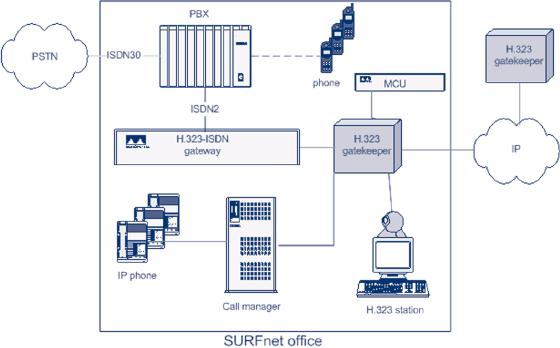
Netherlands is described. An integrated
voice and video environment is a setup
based on
H.323
components (endpoints, MCU and
gateway), a Cisco CallManager
(using the Skinny
protocol),
and a PBX.Therefore this is
also an example of scenario 2b
(Integration with legacy
PBX
systems). Figure 3.8. gives
an example of integrated voice
and video over IP architecture
at
the
SURFnet offices.
The
goal of the integration of voice
and videoconferencing over IP
was to make it possible
to
refer
directly to the user without
knowing his location and
what terminal he is actually
using.
When
someone contacts the user by
any means (PSTN or H.323 of
H.320), the call should
be
completed
by reaching any device the
user may have
operational.The components necessary
to
establish
such an integrated infrastructure
are:
-
a PBX, connected to the
PSTN, in this case a Philips
Sopho, to handle all
incoming regular
voice
calls;
P.60
[IP
Telephony Cookbook] /
IP Telephony Scenarios
-
an H.323 Gateway, in this
case a RADVISION L2W (LAN to
WAN H.323) gateway, on
the
one
side connected to the PBX
(by 2 ISDN lines) and on
the other side to the
local IP
network;
-
an H.323 Gatekeeper, in this
case the build-in gatekeeper
of the RADVISION gateway,
to
route
all calls on the IP network
including making decisions when to
route the call off-net
(to
the
PSTN through the
PBX);
-
a call manager, in this case
a Cisco CallManager, being
the gatekeeper to perform
PBX-like
functions
for the IP-phones;
-
endstations, being the
user's terminal(s).
The
terminals used here
are:
*
IP phones, in this case
Selsius and Cisco IP phones,
registered on the
CallManager;
*
H.323 videoconferencing stations, in
this case VCON Escort Pro
boards in PCs with
MeetingPoint
4.6 and Polyspan
Viewstations (128 and FX),
registered at the H.323
Gatekeeper;
*
regular DECT phones, in this
case Philips, registered at the
PBX.
Figure
3.8. Integrated voice and
video over IP architecture at the
SURFnet offices.
To
allow multipoint calls, an MCU
(RADVISION MCU323) has to be added
and the conference
feature
on the PBX has to be enabled.These
are not necessary functionalities, but
can enhance the
communication
experience.
The
means by which integration was
established was the Dial
Plan that guaranteed
unique
number-addressing
for all devices.The Global
Dialling System (GDS) was
adopted, and the
full
E.164
addressing, number of videoconferencing
and IP Telephony endpoint numbering allow
all
terminals
to be used like regular
phones (see the Section on
`Dial Plans' and
also
http://www.wvn.ac.uk/support/h323address.htm).
Therefore, it is guaranteed that
for
terminals
called/dialled from the PSTN,
the call would be routed to
the PBX. Also the other
way
around
- from the voice and video
over IP terminals, any
regular PSTN number could be
dialled
without
the need for rewriting
the dial string. GDS is
supported by the ViDeNet
H.323
P.61
[IP
Telephony Cookbook] /
IP Telephony Scenarios
gatekeeper
hierarchy, which resembles
the phone system in that it
is a hierarchy of distributed
gatekeepers
that route IP calls based on
prefix resolution.
In
the examples below, A's
phone number is 030-2305367, and
his international phone number is
0031302305367.
His IP phone number is 030-2305167.
For demonstration purposes, he has
also
registered
his H.323 station as
030-2305367. 00 is the international
access code in the
Netherlands,
030 is the area code of
Utrecht, 23053 and 23051
are the prefixes/numberblocks
SURFnet
has control of and 67 is the
local office number assigned to `A'
(Note that the
assignment
is to `A' and not his
devices, because there is more
than 1 numberblock that holds
67
(367
and 167).
A
registers his H.323 station
with the number 67 at SURFnet's office
gatekeeper, which itself
is
registered
with prefixes 3023051 and
3023053 at the Dutch
national gatekeeper, which
itself is
registered
with prefix 31 at the
ViDeNet root gatekeepers.The gateway is
registered as a service at
the
office gatekeeper (with the
prefix 5) and connected to
the PBX. In the PBX, it is
configured
that
all calls to 367 and
167 have to be forwarded to
the gateway. In today's
PBXs, this is easily
configurable
and can often be made
available even as a Web-based
service, so users can
maintain
their
own preferences. At the PBX,
the group number 501 for
group that A belongs to is
also
defined
(the group number for making
all telephones in a group
ring). At the gatekeeper,
the
number
500 is configured as a backup number
that will be called if the
H.323 call is not
answered.The
IP phones are registered
with their 1xx number (in
this case 167) at
the
CallManager,
which itself is registered as a
gateway serving all these
numbers (167, 109, 1xx
etc)
at
the gatekeeper.
The
following situations are not
a complete list of possibilities, but a
several representative
ones:
-
A user on the PSTN calls A
at SURFnet, who has decided to
take all calls on his
H.323 station.
When
the call for 030-2305367
comes in at the PBX of
SURFnet, the PBX looks
for the
terminal
(telephone) 67. It recognises
that the call has to be
forwarded to the gateway.When
the
call
is routed there, the H.323
gatekeeper picks it up and
looks for a terminal with
number 67,
finds
it as A's H.323 station and
forwards the call.The ISDN
signalling is done between
the
PBX
and the gateway, and
the call is set up. A
answers the incoming call on
his
videoconferencing
station, only receiving
audio, since there is no video
attached to the
signal
from
the PSTN user. If A does
not answer on his H.323
station, then the gatekeeper
sees this
and
dials the backup number 501.The
gatekeeper recognises this as a
call for the voice
service
at
the gateway (prefix 5) and
routes the call there.The
gatekeeper passes it off to
the PBX
which
makes all phones in the
group ring. A or one of his
colleagues can then answer
the call
by
picking up any of the phones
in the group.
-
A user, using an IP phone,
dials A's phone number. For
this example A has his
regular phone
registered
with 67 at the PBX and
his H.323 station as 97 at
the gatekeeper.The H.323
IP
phones
or the Cisco IP phones through
the CallManager, when
connected to the
GDS/ViDeNet
system, can find each
other through that hierarchy. If
someone using an IP
phone
dials 0031302305367, then
the CallManager recognises
this as an international call
and
forwards
it to the local gatekeeper.The
gatekeeper sees that it is an international
call and
forwards
it to the ViDeNet root gatekeeper.
Here the prefix 31 is
recognised and the call
is
forwarded
to the Dutch national
gatekeeper.There the prefix
3023053 is recognised and
the call
P.62
[IP
Telephony Cookbook] /
IP Telephony Scenarios
is
forwarded to the SURFnet office
gatekeeper. Here the number 67 is
recognised. Not
having
a
station with 67 registered
there, it falls back to forwarding
the call to the gateway
which
routes
it to the PBX. Here the
phone with 67 is found and
the call is setup.
-
A videoconferencing station dials
A's IP phone. Someone using
an H.323 videoconferencing
station
finds A's number on a card as
00312305167. He dials the number.
Like in the example
above,
through the ViDeNet hierarchy,
the call gets to the
SURFnet office gatekeeper who
sees
that
the call is for 167. In
its tables, it finds that
that number belongs to the
CallManager and
routes
the call there.The
CallManager acts as an H.323-Skinny
gateway and forwards the
call to
the
IP phone.
Note.
If A had also used the
number 030-2305367 for his IP
phone, he would have had to
make
the
choice at the gatekeeper to
route all calls to the
H.323 VC terminal, or to the IP
phone, since
there
cannot be two devices
registered with the same
alias (E.164 no.) at the
same gatekeeper.
Local
dialling between the systems
is also supported: A can
call 97 from his phone to
reach his
H.323
station, or 167 to reach his
IP phone.The other way
around (from IP phone or
H.323
station),
he needs to use a defined
prefix (5 for voice calls,
see above), so 5367 will
ring his normal
PSTN
phone.
If
MCU was involved, people using
either a PSTN device, or an
H.323 IP phone, or a
videoconferencing
station would dial the
routable E.164 number of the
multipoint conference
that
is registered at the office gatekeeper,
as if it was an H.323
terminal.
The
next step towards full
integration is the introduction of a SIP
Proxy and SIP-H.323
Gateway
making
it possible to extend the
range of the devices used
even further.
Note
that the example above
relies on a numeric dialling
plan. Alphanumeric dialling
and routing
is
implemented differently (see Section
2.1.5 on `Addressing').
P.63
Table of Contents:
- INTRODUCTION:Goal, Reasons for writing this document, How to read this document
- TECHNOLOGICAL BACKGROUND:Components, Terminal, Protocols, SIP
- IP TELEPHONY SCENARIOS:Long-distance least cost routing, Integration of VoIP and videoconferencing
- SETTING UP BASIC SERVICES:General concepts, Dial plans, Authentication
- SETTING UP ADVANCED SERVICES:Gatewaying, Accounting gateways, Multipoint conferencing
- SETTING UP VALUE-ADDED SERVICE:Web integration of H.323 services, Web integration of SIP services
- INTEGRATION OF GLOBAL TELEPHONY:Technology, Call routing today,
- REGULATORY / LEGAL CONSIDERATIONS:Regulation of Voice over IP in the European Union, Numbering
- ANNEX A. European IP Telephony Projects:Evolute, SURFWorks, VC Stroom
- ANNEX B. IP Telephony Hardware/Software:Softphones, Hardphones, Gateways
- GLOSSARY:Call Processing Language, Gatekeeper, Media Gateway Control Protocol