 |
[IP
Telephony Cookbook] /
Integration of Global
Telephony
Integration
of Global Telephony -}
7
The
previous chapters described
how to set up an IP Telephony
site and how to use
PSTN
gateways
to call external targets.With growing
support and usage of IP
Telephony, it becomes
more
and more interesting to interconnect IP
Telephony sites and use
the IP network to
transport
calls.
Since dialling IP addresses is obviously
not an option, inter-domain
communication
introduces
the problem of call routing
which can be dealt with in
various ways.This chapter
lists
techniques
and solutions for
inter-domain call
routing.
-}
7.1
Technology
This
section starts with listing
possible mechanisms and
protocols to provide inter-domain
address
resolution.
-}
7.1.1
H.323 LRQ
With
the H.323 protocol, even for
intra-domain routing, there is a
need to localise the
terminals.
Under
normal operations, the user
of an H.323 appliance configures
the H.323 alias
identifier
and,
eventually, the E.164
address number as they are
assigned by the service
administrator.
Later
on, when a call is started,
there is a need for the
terminal to identify the logical
channel of
the
called party (IP address
and destination port) where to
send the signalling
messages.
If
a gatekeeper is not present,
call routing is possible
using the IP address (that
has to be known to
the
calling party) and a standard
destination port. On the
other hand, if a gatekeeper is
present,
both
intra-domain and inter-domain
routing can be performed using
either the alias identifier
or
the
E.164 address. If the called
party is registered within
the same domain as the calling
party, alias
mapping
is performed internally by the gatekeeper
itself, which replies to the calling
party with
the
call signalling address (IP
address and destination
port) of the called
party.
If
the called party is
registered within any other
domain, the gatekeeper has to perform
another
step
before replying to the calling party
with the Admission
ConFirm (ACF)
message
containing
the call signalling address
to be contacted. In order to localise
the terminal within
the
domain,
gatekeepers use the
Location
ReQuest (LRQ).The
LRQ message is transmitted by
the
gatekeeper
to other well-known neighbour
gatekeepers (if any) or to a multicast
address.When
the
LRQ message arrives to the
gatekeeper where the terminal to be
localised is registered, such
a
gatekeeper
answers with Location
ConFirm (LCF)
message containing the information on
the
logical
channel of the called party
to be used for the
signalling messages. At this
point, the
gatekeeper
knows the call signalling
address of the called party
and, depending on the call
model
in
use, it proceeds with the
normal operation (see
Chapter 2).
P.184
[IP
Telephony Cookbook] /
Integration of Global
Telephony
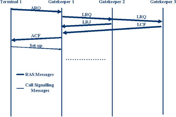
Figure
7.1 Location request
mechanism
In
the case that a gatekeeper
reached by the LRQ message
does not know the
answer to such a
location
request, there are different
possible behaviours depending on
the channel which is
being
used
by the LRQ message. If the LRQ
message was sent on the
RAS channel, then
the
gatekeeper
replies with a Location
ReJect (LRJ),
whereas no action is taken if it
was sent on the
multicast
channel.This simple mechanism is
depicted in Figure 7.1, where
the channel being
used
by
the LRQ messages is the RAS
one.
When
handling calls directed to
terminals on the traditional PSTN,
the zone gatekeeper is
in
charge
of registering the zone
gateways. In such a case,
the gatekeeper will take
care of replying to
the
LRQ messages with a LCF
message containing the call
signal address of the
gateway that is
supposed
to be the one routing the
call to the PSTN
network.
-}
7.1.2
H.225.0 Annex G
Another
H.323-specific mechanism is defined by
H.225.0 Annex G. Unlike the
H.323 LRQ
mechanism
that simply provides a way
to translate an address to an IP address
and port number,
Annex
G allows the coupling of further
information (e.g., pricing
information) to an IP address
and
to use IP address prefixes
for dialling (instead of
just allowing complete
addresses to be
dialled).
Furthermore, H.225.0 Annex G is a protocol
used for communication
between
administrative
domains, meaning a logical collection of
gatekeeper zones (e.g., all
gatekeepers
used
in a university would span the
administrative domain of the university).The
entities that
provide
H.225.0 Annex G services are
called border
elements.
The
smallest information unit
defined by H.225.0 Annex G is
the pattern, which might be
either
a
specific address, an address containing a
wildcard or a range of telephone
numbers. H.225.0
P.185
[IP
Telephony Cookbook] /
Integration of Global
Telephony
Annex
G uses the AliasAddress
structure
to refer to addresses. Such
usage is particularly useful
when
storing specific or wildcard addresses;
thus it is able to carry any
kind of address
information
used by H.323 (see Section
2.2.1.3.1).
Along
with the patterns, H.225.0
Annex G stores some routing
information containing additional
data
about pricing, necessary
access requests, contact
information (which IP/Port to
contact and
what
kind of QoS is provided) and
other protocol-relevant
data.
Patterns
and routing information are
grouped in a so-called address
template, along
with the
time
to live to
indicate how long the
template is valid.The address template
also contains
information
regarding the signalling
protocols that may be used.
Currently, signalling
protocols
include
only the H.3xx protocol family.Templates
are grouped together by an
identifier, known as
a
descriptor. An administrative domain
advertises templates by advertising
descriptors to indicate
the
type of calls it can
resolve.
GK1
T1
BE1
BE2
T2
DescriptorIDRequest
DescriptorIDConfirmation(IDs=d1,d2)
DescriptorRequest(d1)
DescriptorConfirmation
DescriptorRequest(d2)
DescriptorConfirmation
ARQ
LRQ
AccessRequest
AccessConfirmation
LCF
ACF
Setup
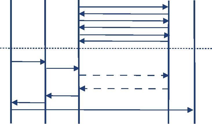
Figure
7.2 Use of H.225.0 Annex
G
On
the protocol side, H.225.0
Annex G defines unidirectional
relationships between
border
elements.
Such a relationship is established by
sending a ServiceRequest
to a
well-known port
(2099)
of a configured peer. Upon
receipt of a positive reply
(ServiceConfirmation)
the
initiating
peer sends a DescriptorIDRequest
to the
other border element, which
replies by
returning
the IDs of all known
descriptors (see Figure 7.2).The first
border element now
requests
each
descriptor by sending a DescriptorRequest. After
all descriptors are sent,
the initiating
border
element knows which addresses
can be reached via the
other border element.
P.186
[IP
Telephony Cookbook] /
Integration of Global
Telephony
When
an endpoint,T1, tries to call
another endpoint,T2, outside of
T1's administrative domain, it
sends
the ARQ message to the
gatekeeper GK1 as usual (see
Figure 7.2). GK1 recognises
the
destination
address in another administrative domain
and asks its border
element, BE1, by
sending
an
LRQ.The border element knows by
previous descriptor exchange
with BE2 how to
contact
the
given address. If BE2
requested that its
authorisation is mandatory for
all calls to that
address
template,
BE1 sends an AccessRequest
to BE2
before replying with a LCF (or
LRJ) message.
When
GK1 receives a LCF message,
the normal H.323 protocol
flows apply.
The
access requests from BE1 to
BE2 might be enforced.The
gatekeeper of the called
endpoint
in
BE2's administrative domain might
send a ValidationRequest
to BE2,
to check if the
incoming
call has been accepted by
the border element.
-}
7.1.3
Telephony Routing Over IP (TRIP)
RFC
3219 `Telephony Routing over
IP' (TRIP) defines the
TRIP protocol that can be
used to
advertise
reachability information for
telephone numbers (e.g.,
E.164) between different
administrative
domains.The TRIP protocol design is
similar to the Border Gateway
Protocol
(BGP)
and uses a binary
packet-encoding.
-}
7.1.3.1
Structure
TRIP
defines communication between
and within IP Telephony Administrative
Domains
(ITAD).
Inter-ITAD communication uses
peer relationships, which
are considered to be
setup
between
two sites upon a trust
relationship.
ITADs
are identified by a globally unique
number.The Internet Assigned
Numbers Authority
(IANA)
registers ITAD numbers to ensure
that a number is globally unique.Taking the amount
of
registered
ITADs as an indicator of the interest in
this protocol, and since exactly
one registered
ITAD
is listed on the IANA Website,TRIP
does not seem to be
widespread.
An
ITAD consists of one or more location
servers, of which at least
one has a peer relationship
to
a
location server of another ITAD.While
inter-ITAD communication is routed on a
hop-by-hop
basis,
the intra-ITAD communication is
done by flooding all internal
peers.
-}
7.1.3.2
Addressing
TRIP
can be used for SIP
and H.323 and allows
disclosure of which signalling protocol
can be
used
to reach an address. For
instance, you can advertise
the `reachability' of a phone
number
+49.421.2182972
via H.323 on host A, while
the same address is
reachable via SIP on
another,
host
B. Since TRIP was intended
to provide a mechanism that
allows selection of egress
gateways,
the
protocol is limited to phone numbers. It
is not possible to advertise
URIs and names
(see
Section
2.1.5) which makes TRIP
unsuitable for all kinds of
inter-domain call
routing.
P.187

[IP
Telephony Cookbook] /
Integration of Global
Telephony
-}
7.1.3.3
Protocol
Initially,
a TRIP Location Server (LS) knows
just its local
addresses.
A:
sip:11,12,13,21
A
B:
sip:14,15
B:
h323:19
C:
sip:10,18,19
C
B
E:
h323:10..18
D:
sip:16,17
E
D
Figure
7.3 TRIP: Location Servers
and their initial
data.
After
establishing connections with
its peer LSs, each
TRIP node advertises all
the routes it
already
has knowledge of.
A:
sip:11,12,13,21
A
C:
sip:10,18,19
B:
sip:14,15
B:
h323:19
C:
sip:10,18,19
C:
sip:10,18,19
B:
sip:14,15
B
C
B:
h323:19
A:
sip:10..13,21
D:
sip:16,17
E:
h323:10..18
D:
sip:16,17
E
D
D:
sip:16,17
E:
h323:10..18
c:
sip:10,18,19
Figure
7.4 TRIP: LS tells peers
their initial data
When
an LS receives data from a
peer LS, it stores it internally.This
data is distributed the
next
time
the LS sends an UPDATE
message
to its peers, but not before
a minimum delay has
elapsed
(see
Figure 7.5). Each node
can decide whether to
advertise itself (or better:
the associated VoIP
server)
as the next-hop server of
the new learned numbers
(Node D) or to pass the
information
of
the original contact (Node
C).
P.188
[IP
Telephony Cookbook] /
Integration of Global
Telephony
A:
sip:11,12,13,21
A
C:
sip:10,18,19
B:
sip:14,15
B:
sip:14,15
B:
h323:19
B:
h323:19
D:
sip:16,17
C:
sip:10,18,19
A:
sip:10..13,21
D:
sip:16,17
C:
sip:10,18,19
B:
sip:14,15
C
B
B:
h323:19
A:
sip:10..13,21
D:
sip:16,17
D:
h323:10...18
E:
h323:10..18
D:
sip:16,17
D:
sip:16,17
D
E
E:
h323:10..18
D:
sip:10,18,19
C:
sip:10,18,19
A:
sip:11..13,21
B:
sip:14,15
B:
h323:19
Figure
7.5 TRIP: Advertising gathered
knowledge
When
a LS collects a continuous range of
telephone numbers (e.g.,
from 770 to 779), it
can
aggregate
this information to a common
prefix. In the example given
in Figure 7.6, Node D
knows
how to reach the numbers
from sip:10 to sip:19. Since
E is not on the path to one
of these
numbers,
it withdraws the routes sent
previously and adds a new
route containing the prefix
`1'.
Node
C could have done the same
for h323:10 to h323:19 when
talking to A, but since C was
configured
not to put itself in the
chain of next-hop servers (or
simply because the feature
is not
supported),
it does not aggregate that
information.
A:
sip:11,12,13,21
B:
sip:14,15
B:
sip:14,15
A
B:
h323:19
B:
h323:19
C:
sip:10,18,19
A:
sip:10..13,21
D:
sip:16,17
C:
sip:10,18,19
D:
h323:10..18
D:
sip:16,16
D:
h323:10..18
C:
sip:10,18,19
B:
sip:14,15
C
B
B:
h323:19
A:
sip:10..13,21
D:
sip:16,17
D:
h323:10..18
E:
h323:10..18
D:
sip:16,17
E
D
D:
sip:1
E:
h323:10..18
D:
h323:19
C:
sip:10,18,19
A:
sip:11..13,21
REM:
D sip:10,16..19
B:
sip:14,15
ADD:
D sip:1
B:
h323:19
D
h323:19
Figure
7.6 TRIP: Route
aggregation
P.189
[IP
Telephony Cookbook] /
Integration of Global
Telephony
-}
7.1.4
SRV-Records
In
February 2000, RFC 2782
was approved, describing a
DNS RR for specifying the
location of
services
(DNS SRV).Before then, there
was a need (and sometimes
there still is) for
users to know
the
exact address of a server providing a
specific service for a
specific domain (i.e., GK or
SIP
Proxy).The
first attempt at point-to-service-specific servers
was MX record, used for
mail servers.
But,
unfortunately, there was no feasible
means of expressing a common
service.
The
SRV records allow
administrators to easily manage
the address propagation of
servers
providing
specific services and could
provide significant service-based
routing advice.
Several
servers
could be used for a single domain,
with defined preference- and
load-balancing. Users
can
easily
ask for a desired service in
a specific domain and obtain a
name or list of server names
that
provide
the service they
requested.
The
SRV RR is a structured collection of
fields, each one with a
name and a specific
meaning:
-
Service
-
Describes the service by its
symbolic name (i.e., LDAP or SIP)
registered by IANA
Assigned
numbers or locally defined. An underscore
is prepended to avoid conflicts
with
common
names that may occur in
DNS. Service name is case
insensitive;
-
Proto
-
Describes the used protocol by
its symbolic name. An underscore is
prepended to avoid
conflicts
with common names that
may occur in DNS. Service
name is case
insensitive.The
most
common values for this
filed are _tcp and
_udp at present;
-
Name
-
Describes the domain name
for which the service is
specified;
-
TTL
- It is
the time to live of the
record. It specifies how
many seconds the record
will be valid
in
the cache of a
questioner;
-
Class
- IN
class is right for SRV
records.The meanings of TTL
and Class are described in
detail
in
RFC 1035;
-
Priority
-
Describes priority of the
target host in range between
0 and 65535.The
records
with
lowest number should be tried
first;
-
Weight
-
Describes a server selection
mechanism for records with
the same priority.
Zero
should
be used if no server selection
should be done. Otherwise, the
higher number gives
the
record
proportionally higher probability of
being selected;
-
Port
-
Describes the service port
on the target host (i.e.,
5060 for SIP).These numbers
are often
the
same as registered IANA assigned
numbers, if the service is running in a
standard port;
-
Target
-
Describes the name of the
target host.The address for
the name could be provided
by
one
or more address records (even A or
AAAA). Use of an alias as
the name is prohibited.
If
the client wants to find a
server for a desired
service, it first tries SRV
lookup. If the
result
contains
one record, the address of
the server is resolved and
used. In a case where there is
more
than
one record, they are
ordered by preference and
weight and tried out. If no
record is
returned,
A
or
AAAA
lookup
should be performed.
$ORIGIN
domain.org.
_ldap._tcp
SRV 0 1 389
ldap1.domain.org
SRV
0 3 389 ldap2.domain.org
SRV
1 0 389 ldap-old.domain.org
*._tcp
SRV
0 0 0
.
*._ucp
SRV
0 0 0
.
P.190
[IP
Telephony Cookbook] /
Integration of Global
Telephony
This
example shows an SRV LDAP
service for the domain
`domain.org'.
A user asking for
LDAP
service, using the TCP
protocol, obtains three records.
During the first round of
attempts
the
user should try to connect
to ldap1.domain.org
or
ldap2.domain.org.Three
quarters
of
attempts should go to ldap1 and
one quarter to ldap2.
If neither of those two is
available, the
user
should then try to connect
to ldap-old.The
last two records determine
that no other
service,
using either TCP or UDP, is
provided in the domain `domain.org'.
More
detailed information about
DNS RR can be found in RFC
2782.
The
two most-used VoIP protocols
are SIP and H.323.The
SIP protocol usually uses
service
names
such as _sip
and
_sips
and
protocol names such as _tcp
and
_udp. H.323,
in its Annex O,
describes
the use of SRV RR to locate
specific services. Service
names and protocols are
more
distinguishable
in H.323 than it is the case
in SIP:
-
h323ls - Location Service, entity
supporting H.225.0
LRQ;
-
h323rs - Registration Service, entity
supporting H.225.0
RRQ;
-
h323cs - Call Signalling,
entity that performs H.225.0
call signalling;
-
h323be - Border Element, entity
that supports communication as
defined in Annex G.
Along
with protocol symbolic names such as
TCP and UDP, sctp
and h323mux are also
used.The
contents
of the Annex O will hopefully be
implemented in new versions of H.323
products
together
with Protocol Specification,Version
5.
As
can be seen, SRV record
helps to find service-specific
servers for desired domains.
In the case
of
VoIP, that means lowering
the need to maintain the
address of distant server's
information at
gatekeepers
and proxies and to ease the
configuration of the clients.
-}
7.1.5
ENUM
One
of the main issues with IP
Telephony today is seamless integration
with the PSTN. As
more
than
one signalling protocol is used,
integration should include them all. In
general, it could be
useful
to have one identifier
(business card contact) for
all available services. By
service, we could
understand
phone call (PSTN, SIP, and
H.323), e-mail,Web and many
others. Such a
unifying
identifier
was chosen to be the E.164
number defined by ITU-T standards. It is
represented as a
number
up to fifteen digits with a leading +.These
numbers are used in the
PSTN and very
often
by
H.323 systems.The next issue
was to find a reasonable
worldwide, deployed database
that
would
hold and provide such
translation information.The DNS
seems to be the right way at
the
moment,
as it is used in probably all
server and client machines
in the Internet.
The
mechanism of the E.164 to URI
DDDS (Dynamic Delegation
Discovery System RFC
3401)
translation and its
applications (ENUM) is described by
RFC 2916 bis draft
(currently 07)
and
by the RFCs listed as a reference in
that draft.
P.191
[IP
Telephony Cookbook] /
Integration of Global
Telephony
The
NAPTR RR is a structured collection of
fields used to store
translation information.The
most
important fields are the
following:
-
Name
Represents an E.164 number encoded as a
domain name.The conversion is done
by
the
following algorithm:
o
All non-digit characters are
removed.
+420-123456789
is transformed to 42123456789
o
Dots are inserted between
each digit
42123456789
is transformed to
4.2.0.1.2.3.4.5.6.7.8.9
o
Order of digits is
reversed
4.2.0.1.2.3.4.5.6.7.8.9
is transformed to
9.8.7.6.5.4.3.2.1.0.2.4
o
To the end is appended
string e164.arpa
4.2.0.1.2.3.4.5.6.7.8.9
is transformed to
4.2.0.1.2.3.4.5.6.7.8.9.e164.arpa
The
e164.arpa domain is used worldwide as
the domain designed for the
ENUM purpose only;
-
Order
-
Specifies the order of NAPTR
rules processing.The ordering is from
lowest to
highest,
i.e., records with the
same order value are
processed according to a combination
of
Preference
and Service;
-
Preference
-
Equivalent to the Priority
field in the SRV RR.The main
difference between
Order
and Preference is that once
a match is found, the client has to
work with records
within
only
one Order, but it can use
records with different Preference
values within the
selected
Order.The
use of SRV records or a
multiple address record is
important for load
balancing;
-
Flags
- These
are strings consisting of
characters (A-Z, 0-9) that
control the way of
rewriting
and
interpreting a record. Flags are
defined by RFC 3404. S, A
and U flags are used as
terminal
flags
terminating the DDDS loop
(RFC 3402) and determining
what should be the
next
action.The
U flag is used to define
that the output of the rule
is an URI.The A flag means
that
the
output is the domain name
and that it should be
resolved by using address
records
(A,AAAA,
A6). It is expected that the
output of the rule with the
S flag is the domain name
for
which
one or more SRV records
exists.The most-used flag
seems to be the U flag.The use
of
the
U flag does not deny
SRV
lookup at
questioner for the domains
returned in URI.These
two
mechanisms can cooperate at a
very large scale;
-
Service
- Service
parameters have the
following form: `E2U+service-type:subtype',
where
E2U
is the mandatory and
non-optional value determining
E.164 to URI translation.The
service-type
and subtype (ENUM-service)
define what the record
can be used for. URI
schemes,
service-types and subtypes
are not implicitly mapped
one to another.This mapping
could
be done by specification of the
ENUM-service. Most important
for VoIP use, are
SIP
(draft-ietf-sipping-e164-04.txt)
and H.323 (draft-ietf-enum-h323-01.txt)
scheme specifications.
The
application decides what
record to use, comparing its
own capabilities and the
user request
with
offered ENUM service
types;
-
Regexp
- This is a
string containing a regular expression
that the questioner applies
to the
original
string. Note that regular
expression is a very
powerful tool and therefore
should be
P.192
[IP
Telephony Cookbook] /
Integration of Global
Telephony
well-constructed
and tested to avoid errors
leading to partial `unreachability' of
the user.The
easiest
regular expression is `!^.*$!', which
covers the whole original
string;
-
Replacement
- This
field is used when the
regular expression is a simple
replacement and its
value
is the domain name that will
be queried next.
A
NAPTR record for number
+420123456798 could look like
this:
$ORIGIN
9.8.7.6.5.4.3.2.1.0.2.4.e164.arpa
IN
NAPTR 10 100 "u"
"E2U+sip"
"!^.*$!sip:smith@domain.org!"
.
IN
NAPTR 10 101 "u"
"E2U+h323"
"!^.*$!sip:smith@domain.org!"
.
IN
NAPTR 10 102 "u"
"E2U+msg:mailto" "!^.*$!mailto:smith@domain.org!"
.
Domain
9.8.7.6.5.4.3.2.1.0.2.4.e164.arpa (user
with E.164 number +420123456789) is
contacted
first
by SIP, second by H.323 and
third by e-mail.
A
wildcard could be used to express
prefixes. Use of wildcards is
under discussion.The
example
could
then look like
this.
$ORIGIN
7.6.5.4.3.2.1.0.2.4.e164.arpa
*
IN NAPTR 10 100 "u"
"E2U+sip" "!^\+420(.*)$!sip:$\1@domain.org!"
.
All
numbers with prefix
+4201234567 will
be translated into
sip:1234567[suffix]@domain.org
and contacted
by SIP.
How
will the whole process work?
In the example the user
dials +420123456789
in
his SIP client;
a
NAPTR query is performed and,
according to the service
provided by the SIP client,
the URI
sip:smith@domain.org
is
formed.Then the client tries
to find the SIP server
for the domain,
domain.org
via an
SRV or A
(AAAA,
A6)
query and connects to the
obtained address.
Using
ENUM along with SRV helps to
provide flexible management of
available services
and
provides
a single contact point that
could be used even from the
PSTN.This is the major task
of
ENUM.
Even ENUM has some problems.The main
problem could be security. Especially if
DNS
is
used as record storage,
information could be easily retrieved
from the database and
used, for
example,
for spamming.
-}7.2
Call routing
today
Since
some of the protocols or
mechanisms, especially those
described in Section 7.1.5,
are quite
young,
there is no widespread support in
existing equipment. An institution that
invested in VoIP
equipment
in 2002/2003 will probably support
only few mechanisms.To
describe how global
call
routing
has been implemented so far, one
needs to distinguish between
H.323 and SIP, since
they
originate
from different backgrounds and
therefore have different
approaches..
P.193
[IP
Telephony Cookbook] /
Integration of Global
Telephony
-}
7.2.1
Using SIP
SIP's
IETF origin has lead to an
early adoption of the usage
of SRV-records to resolve
destination
addresses.
Despite being younger than
H.323, SIP products have
supported this feature since
the
beginning
while most H.323 equipment
still does not.
The
reasons might be that the
usage of DNS is more natural to a
protocol from the IETF than
it
is
to one from the ITU-T. On
the other hand, calling
telephone numbers also
required static peer
configurations.
SIP
products often provide the
possibility to use regular expressions to
ease the management of
routing
tables - at least for those
that are familiar with
the concept.
-}
7.2.2
Using H.323
In
the first version of H.323,
the only way to implement
address resolution was the
usage of
Location
Requests (see Section 7.1.1).This
mechanism required either
peer relationships or
the
reachability
of all gatekeepers in the
Internet via multicast. Since
the latter is obviously
only
usable
for intra-domain address
resolution, sending requests directly to
peers was the only
way to
perform
address resolution..
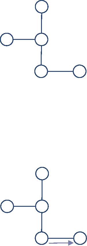
Using
peer relationships works well as long as
there are only a small
number of servers involved,
e.g.,
if you want to connect
branch offices to the main
site (see Figure 7.7).The
mechanism is the
same
as described in Section
4.1.1.2.1.
Figure
7.7 Using peers to route
external calls.
This
structure does not scale to
a large number of connected sites.
Manually configuring
each
server
and its prefixes is
error-prone and exhausting at
best.The solution to this problem could
be
the
usage of SRV-Records (see
Section 7.1.4) or even
TXT-Records that where defined
for
H.323
since version 2, but since
most IP Telephony solutions where
used for intra-domain
P.194
[IP
Telephony Cookbook] /
Integration of Global
Telephony
communication
and as a PBX replacement, dynamic
address resolution was not
implemented for
a
long time.
For
this reason and because of
`legacy' VoIP equipment, the
idea of a gatekeeper hierarchy
was
born.
A gatekeeper that cannot
resolve an address itself
sends a location request to a higher
level
gatekeeper
that acts as a clearing
house for this request.This
gatekeeper may also need to
ask a
higher-level
gatekeeper.
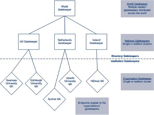
The
gatekeeper hierarchy is oriented at
political or organisational structures.
On top, there is
a
world gatekeeper that can
route calls to the top level
gatekeepers of all
nations.The
sub-structuring
within a nation may vary. A
dialling scheme must be
applied to address
the
gatekeepers.To
provide a testbed,ViDeNet came up
with the Global Dialling
Scheme (GDS) that
is
explained in more detail in Section
7.2.2.1.The problem with the GDS is
that, in its original
form,
it differs from the E.164
numbering space except in country
codes.
Figure
7.8 Gatekeeper
hierarchy
-}
7.2.2.1
Global Dialling
Scheme
The
Global Dialling Scheme (GDS) is a new
numbering plan for the
global video and voice
over
IP
network test bed, originally
developed by HEANet, SURFnet
and UKERNA. It resembles
the
international
E.164 telephone system numbering
plan, with some
exceptions.With the GDS,
you
can
number each participating videoconferencing endpoint,
MCU conference and gateway.
GDS
provides
easy, uniform dialling throughout
the world.
7.2.2.1.1
The Global Dialling Scheme
explained
Each
basic number consists of four
parts:
<IAC><CC><OP><EN>
P.195
[IP
Telephony Cookbook] /
Integration of Global
Telephony
International
Access Code (IAC)
This
is also called the world
gatekeeper prefix. It is defined as
00;
Country
Code (CC)
This
follows the ITU international access
code system. For instance,
the country code for
the
Netherlands
is 31. See the following
PDF document for country
codes:
http://www.itu.int/itudoc/itu-t/ob-lists/icc/e164_717.pdf
Organisational
Prefix (OP)
Many
national research organisations
follow the telephone number
system in their country
and
use
their area code and
organisational telephone exchange
prefix. For instance, SURFnet's OP
is
302305.
However, there are other
possibilities. Some organisations
use their administration
number
or make one up. National
research organisations or
videoconferencing service
providers
could
instead supply you with an
OP, as was the case
with the old ViDeNet
system. In any case,
your
OP must be unique within a country. If
you do not know your OP,
please contact your
videoconferencing
service provider, your national
gatekeeper or the NASM working
group (see
below);
Endpoint
Number (EN)
Your
EN can be any number and it is
decided by each organisation.
However, we recommend
that
it is no longer than seven digits.
Each endpoint number MUST be unique
within the
organisation.
Both 305 and 1234567
are fine examples as long as they
are unique.
7.2.2.1.2
Examples
The
Megaconference informal test
MCU:
00(IAC)
1(CC) 189(OP) 7201234(EN)
Typed
into your videoconferencing endpoint, the
number would simply look
like:
0011897201234
7.2.2.1.3
Alphanumeric dial
plan
The
GDS also defines an
alphanumeric dial plan.This part is
equal to the alphanumeric
dial plan
of
the old ViDeNet and
should be in the form:
<station
ID>@<fully qualified
domain
name
of the institution>
An
example is: egon.verharen@surfnet.nl
7.2.2.1.4
More information
More
information on the GDS and
the Numerical Addressing
Space Management
(NASM)
working
group overseeing its
development can be found
at:
-
http://www.wvn.ac.uk/support/h323address.htm
-
http://www.vide.net/workgroups/nasm/index.shtml
P.196
[IP
Telephony Cookbook] /
Integration of Global
Telephony
-}
7.2.2.2
Problems
The
use of H.323 LRQs and of
a gatekeeper hierarchy is an easy
way to enable all kinds of
H.323
equipment
to reach other sites. On the
other hand, there are
some problems that make
this
solution
less desirable:
-
Latency
- The
address resolution process
may include multiple hops
(e.g., from an
organisational
gatekeeper to another gatekeeper in
another country, there are at
least four hops).
Each
hop increases the time
needed to process the
request and eventually forward
it. So it may
take
several seconds to resolve an
address even before the
call setup can begin.
Speaking of call
setup,
one should consider that it
is possible for a gatekeeper to put
itself into the call
signalling
path.
By changing the destination
address of a LCF
message
to its own address, the
higher level
gatekeeper
forces the requesting
gatekeeper to pass the call to
him.This may be useful
for
security
reasons, e.g., when a
gatekeeper's policy only
accepts incoming external calls
that
originate
from a trusted higher-level gatekeeper to
avoid being spammed from
an
uncontrollable
source. But again this
adds some latency to the
call setup.
-
Bottlenecks
and single point of failure
- Every
higher-level gatekeeper resolves
addresses
or
routes of calls for its
subordinate gatekeepers. It is critical
that a gatekeeper is operational
and
can
handle all incoming
requests.To avoid bottlenecks or
complete loss of higher-level
gatekeepers,
these must have a redundant
layout, should have different
locations and should
use
load-sharing
mechanisms.
-
Cost
- Running
a higher-level gatekeeper is expensive,
because one must provide
hardware
that
guarantees continuous
availability..
-
Feature
limit - The
usage of a hierarchy limits
the availability of protocol features to
the
feature
set of the `dumbest'
gatekeeper in the chain.
Current versions of H.323
do, for example,
carry
more attributes than just
AliasName
and
IPAddress, as it is
the case in the Location
Request
(LRQ); such
additional information specifies desired
protocols or a hop count. A
gatekeeper
that uses a lower-protocol
version will ignore those
attributes and will not
add that
information
in its reply.While this is
annoying, it is still tolerable
since advanced
address
resolution
is not that important. But
it is even worse when the
call signalling is routed
through
the
gatekeepers as well. In this
case, it might happen that
two communication partners
using
new
equipment that supports a special
feature (e.g., transmitting an image of
the calling party
on
call setup) can not
use this feature because of
a gatekeeper in the call
path that is not
aware
of
the feature. So,
hierarchical address resolution
and call routing hinder
research on IP
Telephony.
-
Protocol
limitation - By
nature, the gatekeeper
hierarchy is limited to H.323
and is difficult
to
merge with the SIP
world. It is, of course,
possible to provide gateways to
SIP proxies but the
infrastructure
and the configuration will
get complex and more
error-prone.
P.197
[IP
Telephony Cookbook] /
Integration of Global
Telephony
-}7.3
Utopia: setting up global IP
Telephony
To
set up an infrastructure to provide
address resolution for international
addresses that
supports
H.323
and SIP, not all of the
protocols described in Section
7.1 are useful:
-
H.323 LRQs - Among other
reasons this solution is not
suitable because it does not
support
SIP;
-
H.225.0 Annex G - Does not
support SIP;
-
TRIP - Supports H.323 and
SIP but can be used for
telephone numbers
only;
-
ENUM + SRV-Records - Supports SIP
and H.323 and can be
easily configured to
support
more
protocols. It does not
impose a network of peer
relationships because of its
decentralised
nature.
It supports URIs and
telephone numbers.
It
is obvious that the combined
use of ENUM for mapping
telephone numbers to URIs
and
SRV-Records
to resolve URIs upon a well-understood
and scalable mechanism like
DNS is an
ideal
solution to this problem.
-}7.4
Towards Utopia
The
use of ENUM and SRV-Records
might be the ideal solution, but it
still has some
obstacles
that
need to be overcome. Most
available VoIP products do
not support both features.There
are
some
products, especially in the
SIP world, that support
SRV-Records but just a few
that support
ENUM
as well. Products that are
already in use probably will
not be able to resolve
telephone
numbers
via ENUM.
Some
vendors will offer
ENUM/SRV-Records capabilities by software
upgrades, but not
everyone
will.To protect investments
that have already been
made, it is necessary to find
a
solution
that integrates older IP
Telephony equipment.
-}
7.4.1
Call Routing Assistant (CRA)
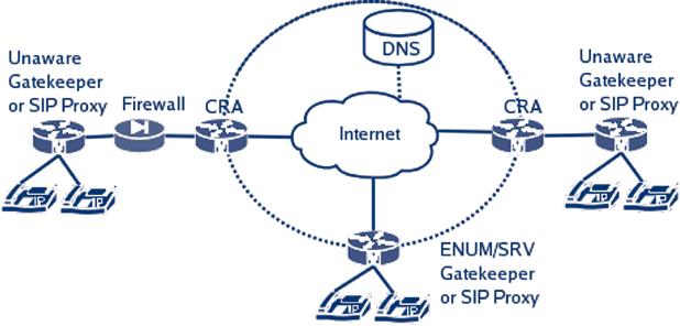
To
enable an ENUM-unaware H.323
Gatekeeper or SIP Proxy to
use this feature, one
can make
use
of the ability to configure a
default server (further on called
Call Routing Assistant
(CRA))
that
all unknown calls shall be
routed to. Such a configuration
option is provided by nearly
all IP
Telephony
servers.The Call Routing
Assistant will act as the
VoIP equivalent of a default
gateway
and
perform the call routing
instead of the ENUM-unaware
server.
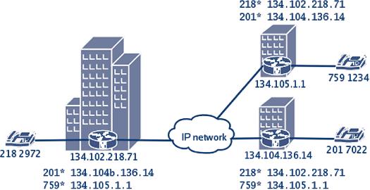
Such
a Call Routing Assistant could
also be used as a firewall to
protect the internal IP
Telephony
server
by opening just a single
hole in the CRA as a gateway
for external communication.
If
the internal IP Telephony server
only supports one signalling
protocol, the CRA could include
SIP/H.323
Gateway functionality.
P.198
[IP
Telephony Cookbook] /
Integration of Global
Telephony
The
Call Routing Assistant is
not a special product. In theory, every
IP Telephony server that
can
be
configured to route or resolve
calls, without registering
the other server, can be
used in this
place.
Efforts are being made by
the Center for Computing
Technology in Bremen, Germany to
provide
an easy-to-use, open source CRA
implementation.
Figure
7.9 Use of a Call Routing
Assistant
P.199
Table of Contents:
- INTRODUCTION:Goal, Reasons for writing this document, How to read this document
- TECHNOLOGICAL BACKGROUND:Components, Terminal, Protocols, SIP
- IP TELEPHONY SCENARIOS:Long-distance least cost routing, Integration of VoIP and videoconferencing
- SETTING UP BASIC SERVICES:General concepts, Dial plans, Authentication
- SETTING UP ADVANCED SERVICES:Gatewaying, Accounting gateways, Multipoint conferencing
- SETTING UP VALUE-ADDED SERVICE:Web integration of H.323 services, Web integration of SIP services
- INTEGRATION OF GLOBAL TELEPHONY:Technology, Call routing today,
- REGULATORY / LEGAL CONSIDERATIONS:Regulation of Voice over IP in the European Union, Numbering
- ANNEX A. European IP Telephony Projects:Evolute, SURFWorks, VC Stroom
- ANNEX B. IP Telephony Hardware/Software:Softphones, Hardphones, Gateways
- GLOSSARY:Call Processing Language, Gatekeeper, Media Gateway Control Protocol