 |
Page
45 of 97
place
time slot boundaries
accurately. Protection against TDM
cross-talk is achieved by putting
guard
times in
the slots. Data is not
packed end-to-end in a time
slot. Rather, there is
either a dead space,
or
dummy
bits or some other mechanism
built into the TDM protocol
so that if data slides from one
slot to
another
its impact on BER is
minimal.
With
WDM cross-talk arises because
the optical signal spectrum
for a given link placed upon
one
particular
(center) wavelength is not
bounded in wavelength (equivalently
frequency). This is a
consequence
of it being a physical signal
that can actually be generated. The
optical signal spectrum
will
spill
over onto the optical
signal spectrum for another
link placed at another (center)
wavelength. The
amount
of spillage depends upon how
close the wavelengths are and
how much optical filtering
is built
into
the WDM to buffer it. The
protection against cross-talk here is
measured by a parameter called
isolation.
This is the attenuation (dB)
of the optical signal placed at one
(center) wavelength as
measured
at
another (center) wavelength.
The greater the attenuation
the less effective spillage
and the less impact
on
BER.
At
the present time, clock
stability for digital
circuitry is such that TDM
cross-talk presents no
real
impact
on BER in the context of
premises data communications and at
the composite link speeds
that
can
be accommodated. The TDM cross-talk
situation may be different
when considering
WANs.
However,
this is the case in the
premise environment. The situation is
not as good for WDM.
Here,
depending
upon the specific WDM design,
the amount of isolation may
vary from a low value of 16
dB
all
the way to 50 dB. A low
value of isolation means
that the impact upon
BER could be significant.
In
such
situations WDM is limited to
communications applications that can
tolerate a high BER.
Digital
voice
and video would be in this
group. However, LAN traffic
would not be in this group.
From the
perspective
of BER generated by cross-talk TDM is
more favorable than
WDM.
CHAPTER
4
EXPLOITING
THE DELAY PROPERTIES OF FIBER OPTIC CABLE FOR
LOCAL
AREA NETWORK (LAN) EXTENSION
Fiber
optic cable provides a way
for extending reach of Local
Area Networks (LANs). If you
are well
versed
on the subject of LANs you
are welcome to jump right
into this subject and skip
the next two
subchapters.
However, if you have not
been initiated into LAN
technology then you will
find the
subjects
covered in these next two
subchapters worthwhile reading.
4.1
Brief History of Local Area
Networks
Two
full generations ago, in the early days
of the data revolution, each
computer served only a
single
user.
In the computer room (or at
that time 'the building') of
an installation there was 1 CPU, 1
keyboard,
1
card reader, (maybe) 1 magnetic tape
reader, 1 printer, 1 keypunch machine
etc. From a usage point
of
view
this was highly inefficient.
Most data processing managers
were concerned that this
highly
expensive
equipment spent most of the
time waiting for users to
employ it. Most data
processing
managers
knew this looked bad to
the Controllers of their
organizations. This led to
the pioneering
development
of time-sharing operating systems by MIT
with Project MAC.
Time
sharing opened up computational
equipment to more than 1
user. Whole departments,
companies,
schools
etc. began making use of
the expensive computational
equipment. A key element in
time sharing
Page
46 of 97
systems
concerned the keyboard. A computer
terminal replaced it. The
multiple terminals
were
connected
to the CPU by data
communications links. There was a
marriage of computation and
data
communications.
In particular, the data
communications was mostly (though
not exclusively)
premises
data
communications.
Throughout
the years time sharing led
to distributed computation. The
idea of distributed
computation
being
that applications programs
would reside on one central
computer called the Server.
Applications
users
would reside at PCs. When an
applications user wanted to run a
program a copy of it would
be
downloaded
to him/her. In this way
multiple users could work
with the same program
simultaneously.
This
was much more efficient than
the original time sharing.
Distributed computation required a
data
communications
network to tie the Server to
the PCs and peripherals.
This network was called a
Local
Area
Network (LAN). This network
had to have high bandwidth. In
fact, it had to accommodate speeds
that
were orders of magnitude greater than
the original time sharing
networks. Entire
applications
programs
had to be downloaded to multiple users.
Files, the results of
running applications
programs,
had
to be uploaded to be stored in central
memory.
LANs
first came on the scene in a
noticeable sense in the late
1970's. From that time until
the present
many
flavors of LANs have been
offered in the marketplace.
There are still a number of
different flavors
each
with its group of advocates
and cult following. However,
some time around the
late 1980's the
market
place began to recognize Ethernet as
the flavor of choice. All of
the discussion in the sequel will
concern
only Ethernet.
The
Ethernet LAN architecture had its
origins in work done at Xerox Palo
Alto Research Center
(PARC)
by Robert Metcalf in the
early 1970's. Metcalf later
went on to become the
founder of 3COM.
Xerox
was later joined by DEC and
Intel in promoting Ethernet as
the coming LAN standard. In
the
development
of the Ethernet LAN architecture
Metcalf built upon previous
research funded by
the
Advanced
Research Projects Agency
(ARPA) at the University of
Hawaii. This ARPA program
was
concerned
with an asynchronous multiple
access data communications
technique called
ALOHA.
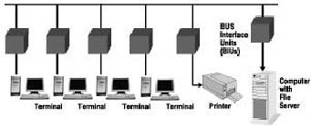
The
basic operation of an Ethernet LAN can be
briefly explained with the
aid of Figure 4-1.
This
illustration
indicates various data
equipment that all need to
communicate with each other.
The data
equipment
constitute the users of the
LAN. Each is a Source and User within the
context of the
discussion
of Chapter 1. The location on
the LAN of each data
equipment unit is termed the
station.
Figure
4-1: Ethernet Bus
architecture
The
communication between the
data equipment is accomplished by
having all the data
equipment tap
onto
a Transmission Medium. Each station
taps onto the Transmission
Medium. The
Transmission
Medium
is typically some type of cable. As
shown in Figure 4-1 it is
labeled Broadcast Channel -
The
Page
47 of 97
Ethernet
Bus. The Bus Interface
Units (BIUs) provide the
essential interfacing at a station
between the
data
equipment and the Broadcast Channel.
That is, they provide
the transmit/receive capability and
all
needed
intelligence.
It
is an essential feature of the Ethernet
LAN architecture that any
data equipment can transmit to
any
other
data equipment and any data
equipment can listen to all
transmissions on the Broadcast
Channel,
whether
intended for it or for some
other data equipment user.
Implicitly, the Ethernet
architecture
assumes
that there is no coordination in
the transmissions of the
different data equipment.
This is quite a
bit
different from the sharing
of a Transmission Medium by TDM where
coordination is essential.
Transmitted
data only goes in its
assigned slot.
Now
how does an Ethernet LAN
operate? It operates by making
use of three essential items.
First, it
employs
a Carrier Sense Multiple
Access/Collision Detection (CSMA/CD)
protocol. Secondly, data
to
be
communicated is enveloped in packets
that have the addresses of
the data equipment
units
communicating.
The packet has the address
of the equipment sending
data (the origin) and the
data
equipment
that is the intended
recipient (the destination).
Thirdly, the Ethernet Bus -
the Transmission
Medium
- is taken as passive and supports
broadcast type transmissions.
The way in which the
Ethernet
LAN
architecture uses these
items is explained briefly
below.
Consider
a specific data equipment
unit at its station. This
will be our data equipment
unit, station and
BIU
of interest. For the sake of
an example, suppose it is a PC wanting to
communicate with the
Computer
with File Server at its
station. Before attempting to
transmit a data packet onto
the Ethernet
Bus
our terminal's BIU first
listens to determine if the
Bus is idle. That is, it
listens to determine if
there
are
any other packets from
other data equipment already
on the Bus. It attempts to
sense the presence of
a
communication signal representing a
packet, a carrier, on the Bus.
Our BIU and any BIU
have
circuitry
to perform this Carrier Sensing. An
active BIU transmits its packet on
the Bus only if the
Bus
has
been sensed as idle. In
other words, it only
transmits its packet if it has
determined that no
other
packet
is already on the Bus -
carrier is absent. If the Bus is
sensed as busy- carrier is
present- then the
BIU
defers its transmission until
the Bus is sensed as idle
again. This procedure allows
the various data
equipment
to operate asynchronously yet
avoid interfering with one
another's communications.
However,
it may be that a carrier has
not sensed an existing packet is
already on the Bus.
Transmission
of
a packet by the BIU of interest begins
but there are still
problems. There are
propagation delays and
carrier
detection processing delays. Because of
these, it may be that the
packet from our PC's BIU
still
interferes
with, or collides with, a packet
transmitted by another equipment's BIU.
This interfering
packet
is one that has not yet
reached our BIU by the end of
the interval in which it had
performed the
carrier
sensing. A BIU monitors the transmission
of the packet it is sending out to
determine if it does
collide
with another packet. To do this it
makes use of the broadcast
nature of the transmission
medium.
A
BIU can monitor what it has
put on the Ethernet Bus and
also any other traffic on
the Ethernet Bus.
Our
BIU and any BIU has circuitry to
perform Collision Detection.
The BIU that transmitted
the
interfering
packet also has circuitry to perform
Collision Detection.
When
both BIUs sense a collision
they cease transmitting. Each BIU
then waits a random amount
of
time
before re-transmitting - that is sensing
for carrier and transmitting
the packet onto the bus.
If
another
collision occurs then this
random time wait is repeated
but increased. In fact, it is increased
at an
exponential
rate until the collision
event disappears. This approach to
getting out of collisions is
called
exponential
back off.
4.2
Transmission Media Used To Implement An
Ethernet LAN
Let
us direct attention now to
the Transmission Medium that
is used to implement the
Broadcast
Page
48 of 97
Channel,
the Ethernet Bus.
Early
implementations of Ethernet LANs
employed thick coaxial cable.
Actually, it was thick
yellow
coaxial
cable - the original recipe Ethernet
cable. The cable was defined by the
10Base-5 standard. This
implementation
was called Thicknet. It could
deliver a BER of 10-8. It supported a data rate of
10
MBPS.
The maximum LAN cable segment length was
500 meters. The segment length is the
maximum
distance
between data terminal
equipment stations. These are
attractive features.
Unfortunately,
the thick coaxial cable was
difficult to work with. As a
result, second wave
implementations
of Ethernet LANs employed
thin coaxial cable. The cable was
RG58 A/U coaxial cable
-
sometimes called Cheapernet. This cable was
defined by the 10Base-2 standard.
The implementation
was
called Thinnet. It supported a
data rate of 10 MBPS. But, it had a
BER somewhat degraded
relative
to
Thicknet. The LAN cable segment length
was reduced to the order of 185
meters.
Thinnet
ultimately gave way to the
replacement of coaxial cable with
Unshielded Twisted Pair cable
(UTP).
This came about through an
interesting merging of the
Ethernet LAN architecture with
another
LAN
flavor called StarLAN, an AT & T
idea.
StarLAN
was based upon what a Telco,
a phone company, normally
does for businesses that
is, provide
voice
communications. The Transmission
Medium a Telco uses within a
facility for voice
communications
is Unshielded Twisted Pair cable (UTP).
It provides voice communications
within a
facility
and to the outside world by
connecting all of the
phones, the handsets, through a
telephone closet
or
wiring closet. The distance
from handset to telephone closet is
relatively limited, maybe 250
meters.
The
StarLAN idea was to take this
basic approach for voice and
use it for a LAN. The LAN
stations
would
be connected through a closet.
The existing UTP cable present in a
facility for voice would
be
used
for the LAN data traffic.
There would be no need to
install a new and separate
Transmission
Medium.
Installation costs would be
contained. Unfortunately, StarLAN
only supported 1 MBPS.
It
never
got off the
ground.
However,
in 1990 aspects of StarLAN were
taken and merged with the
Ethernet LAN architecture.
This
resulted
in a new Ethernet LAN based
upon UTP and defined by the
10Base-T standard. It was with
this
UTP
approach that Ethernet really
took off in the market
place.
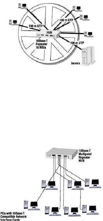
Ethernet
under the 10Base-T standard
has a hub and spoke
architecture. This is illustrated in
Figure 4-2.
The
various data equipment
units, the stations, are
all connected to a central
point called a
Multipoint
Repeater
or Hub. The connections are
by UTP cable. This architecture
does support the
Broadcast
Channel-Ethernet
Bus. This occurs because
all data equipment units can
broadcast to all other
data
equipment
units through the Hub.
Likewise, all data equipment
units can listen to the
transmissions from
all
other data equipment units
as they are received via
the UTP cable connection to
the Hub. The
Hub
takes
the place of the telephone
closet. The Hub may be
strictly passive or it may
perform signal
restoration
functions.
Page
49 of 97
Figure
4-2: 10Base-T hub-and-spoke
architecture
The
illustration Figure 4-3
indicates how the 10Base-T
topology may actually look
in an office set-up at
some
facility. Here the data
equipment units are all
PCs. One serves as the
file server. The
illustration
shows
what is usually referred to as a
10Base-T Work Group. It may
serve one specific department in a
company.
By connecting together these
work groups Ethernet LANs
may be extended. This
is
accomplished
by connecting hubs using LAN
network elements called bridges,
routers and switches. A
description
of their operation is beyond
the focus of the present
discussion.
Figure
4-3: Ethernet operating as a
10Base-T work
group
But,
let us get back to 10Base-T. It supports
a data rate of 10 MBPS. It has a
BER comparable to
Thinnet.
However, the LAN segment length is
reduced even further. With
10Base-T the LAN segment
length
is only 100 m - a short distance but a
distance that is tolerable for
many data equipment
stations
in
a typical business. However, it may be
too short for others.
This is a place where fiber
optic cable can
come
to the rescue.
Page
50 of 97
For
the LAN market place 10Base-T was
far from the last
word. It led to the
development of 100Base-T
-
Fast Ethernet. It is also based on
using UTP cable for
transmission medium. However, it
supports a
data
rate of 100 MBPS over cable segments of
100 m.
Fast
Ethernet, itself, is not the
end of the road. Vendors are
starting to promote Giga Bit
Ethernet which
is
capable of supporting 1 GBPS.
However, we will stop at Fast Ethernet
and the problem that both
it
and
10Base-T have - the short
cable segment of 100 m.
Before
continuing it will be worthwhile to
define two terms that come
up in discussing Ethernet
characteristics.
These are 1) Network Diameter and 2)
Slot Time.
The
Network Diameter is simply
the maximum end-to-end distance
between data equipment
users,
stations,
in an Ethernet network. It is really
what has been referred to
above as the cable segment. The
Network
Diameter is the same for
both 10Base-T and 100Base-T, 100
m.
After
a BIU has begun the
transmission of a packet the Slot
Time is the time interval
that a BIU listens
for
the presence of a collision
with an interfering packet. The
Slot Time cannot be
infinite. It is set
for
both
the 10Base-T and 100Base-T
Ethernet architectures. It is defined
for both standards as the
time
duration
of 512 bits. With a 10Base-T
Ethernet network operating at 10
MBPS the Slot Time
translates
to
51.2µsec.
With a 100Base-T Ethernet
network operating at 100 MBPS
the Slot Time translates
to
5.12µsec.
4.3
Examining the Distance
Constraint
The
distance constraint of an Ethernet LAN is
the Network Diameter. As
noted above this is 100 m
for
both
the 10Base-T and 100Base-T
implementations. This may
not be enough for all
potential users of an
Ethernet
LAN. Now how do you support
LAN users that are separated
by more than this
100-m
constraint?
To deal with this question it is
important to understand where
this constraint comes from
and
what
is driving it.
Many
people believe that the
Network Diameter is set
strictly by the attenuation
properties of the UTP
copper
cable connecting data equipment to
the Hub. This is erroneous.
Attenuation does affect
the
Network
Diameter, but it is not the
dominant influence. However, if it
were, you would be able to
see
the
immediate possibilities of improving it
by using fiber optic cable
rather than UTP copper cable.
The
significantly
less attenuation of fiber
optic cable would boost the
Network Diameter. No, it is
not
attenuation
but instead the Slot Time
that really sets the
Network Diameter.
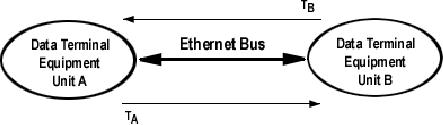
The
Slot Time is related to the
amount of time delay between
a transmitting BIU and the
furthermost
receiving
BIU. The diagram showed in
Figure 4-3 illustrates the
Slot Time issues to be
discussed now.
Here
we show two data equipment
users of an Ethernet LAN - either
10Base-T or 100Base-T - it doesn't
matter.
These are labeled as Data Terminal
Equipment Unit A and Data Terminal
Equipment Unit B.
For
brevity they will be referred to as
Unit A and Unit B. The BIU's
are taken as subsumed in the
ovals.
Page
51 of 97
Figure
4-4: 2 Stations communicating on an
Ethernet Bus. Delays
shown.
Suppose
Unit A transmits a data packet
over the Ethernet Bus to
Unit B. The transmitted data
packet
travels
along the Ethernet Bus. It
takes a time interval of
TA seconds to reach Unit B. In
the meantime,
Unit
B has performed carrier sensing and
has determined, from its
perspective, that the
Ethernet Bus is
not
busy and so it also begins to transmit a
data packet. From a collision
detection point of view
the
worst
case occurs when Unit B
begins to transmit its data packet
just before the data packet
from Unit A
arrives
in front of it. Why is this
worst case? When the
Unit A data packet arrives at
Unit B, Unit B
immediately
knows that a collision has
occurred and can begin recovery
operations. However, Unit
A
will
not know that there
has been any collision
problem until the data
packet from Unit B arrives in
front
of
it. This packet from Unit B
takes a time interval of
TB seconds to arrive at Unit
A. Putting this
together
Unit A has to wait at least
TA +
TB seconds before it can detect
the presence/absence of a
collision.
There is some additional
time needed to sense the
presence/absence of a collision at both
Unit
A
and Unit B. The collision
detection processing time is denoted as
TC.
For 100Base-T networks
a
typical
value for this is 1.12
µsec.
The Slot Time is the
sum TA + TB
+ TC.
TA and
TB usually can be taken as
equal and denoted as t. Putting these
together brings:
τ
=
(Slot Time- TC) / 2
The
one way delay, τ, is equal
to the distance between Unit A and
Unit B divided by the
velocity of
transmission
between Units A and B. The
maximum distance is of course the Network
Diameter. The
velocity
of transmission will be denoted by 'V.'
This is the speed of an
electromagnetic wave on
the
Ethernet
Bus. Applying these
brings:
Network
Diameter = (V/2)(Slot Time-
TC)
The
Slot Time is fixed by the
10Base-T and 100Base-T Ethernet
standards. TC is a function of BIU
design.
It is evident then that it is
the value of V that really
drives the Network Diameter.
In
characterizing
the Ethernet Bus you
usually deal with the
inverse of V. For UTP copper cable
V-1 is
approximately
8 nsec/m. Consider a 100Base-T
Ethernet LAN. Applying this
value for V-1 above brings
a
value of 250 m for the
Network Diameter. On the face of it
this is quite a bit better
than the 100-m
allotted
for the Network Diameter by
the standard. The difference is
accounted for by a number of
delay
items
that were excluded from
the example. These were
excluded in order to bring
out the principle
point
- the dependence of Network
Diameter on V-1. This difference is taken
up by margin allotted
for
other
processing functions. These functions
include the delay through
the Hub. They include
processing
delays
in software at the interface
between the data equipment
and its BIU. The margin is also
allotted
for
deleterious properties of cable.
Page
52 of 97
However,
the essential point remains.
The achievable Network
Diameter is determined by the
delay
through
the transmission medium. The
speed of V-1 through UTP copper cable
results in a Network
Diameter
of 100 m.
Consider
a fiber optic cable. Typically,
the value of V-1 is 5 nsec/m for multi-mode
fiber optic cable.
This
is almost 50% lower than
for UTP copper cable. Applying
this value in the above
example would
bring
a Network Diameter of 400 m, quite a
bit more than 250 m.
By
using a fiber optic cable
you can connect data
equipment stations to the LAN
that are much
further
apart
than the 100 m distance allowed
for by the assumed UTP
copper cable in 10Base-T or
100Base-T
LANs.
You can do this because the
velocity of light through a
fiber optic cable is much
faster than the
group
velocity of electromagnetic waves in
copper cable- the speed of
current in copper cable. You can
do
this because the
transmission delay, V-1, of a packet traversing a fiber
optic cable is about 50%
lower
than
it is for UTP copper cable.
How
would you do it? How
would you exploit a fiber
optic cable to bring distant
users into a UTP
copper
cable based Ethernet LAN?
How would you accommodate
really distant stations to a
10Base-T
or
100Base-T Ethernet LAN, stations
much further than the
Network Diameter?
In
order to do this you need to
connect them to the Hub
using a fiber optic cable.
This may be either a
multi-mode
or single-mode fiber optic cable.
However, neither the
Ethernet Hub nor the BIU at
the
distant
data equipment user knows
anything about signaling on a
fiber optic cable
Transmission
Medium.
So, at the Hub you
need some type of equipment
that will take the 10Base-T or
100Base-T
packets,
in their electrical format, and
convert it to light to propagate
down a fiber optic cable. You
need
the
same equipment at the
distant data equipment's BIU
for transmission toward the
Hub. Similarly, you
need
this device to be able to take the
light wave representations of a packet
coming out of the
fiber
optic
cable and convert it to an electrical
format recognizable by the
Hub or the BIU. This is
called a
LAN
Extender.
By
using a LAN Extender you get a distance
benefit. In addition, on the
particular LAN link you get
the
other
benefits available with
fiber optic cable. These include
protection from ground
loops, power surges
and
lightning.
4.4
Examples of LAN Extenders Shown In Typical
Applications
Telebyte
offers a variety of LAN Extenders. These
are now described.
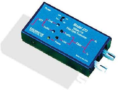
Model
373 10Base-T to Multimode Fiber Optic
Transceiver
This
unit is pictured in Figure
4-5. It extends the distance of a
10Base-T Ethernet LAN to over 2
km.
The
Model 373 10Base-T to Multi-Mode
Fiber Optic Transceiver
takes 10Base-T Ethernet
signals and
converts
them to/from optical signals
that are transmitted/received
from multi-mode fiber optic
cable.
Page
53 of 97
Figure
4-5: Model 373 10Base-T to
Multi-Mode Fiber Optic
Converter
The
Model 373 has a group of
five LED's. These indicate
the presence of the fiber
optic link, traffic
going
back and forth in both directions,
the presence of a collision and
power. The unit even
includes a
Link
Test switch. This assures
compatibility between older and
newer Ethernet adapters. It
allows the
enabling/disabling
of the Link Test heart
beat option.
The
Model 373 uses ST connectors
for the fiber optic cable.
It is designed for
transmission/reception
over
62.5/125 multi-mode fiber
optic cable. On the 10Base-T
port side, it is in full compliance
with the
IEEE
802.3 specification. The
Model 373 is also in full compliance with
the Ethernet
10Base-FL
standard.
This is the standard for
using multi-mode fiber optic
cable to extend the Network
Diameter of
a
10Base-T Ethernet LAN.
The
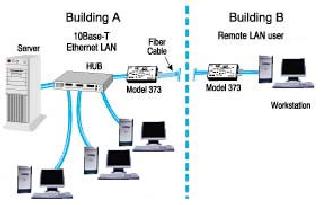
Model 373 is illustrated in a typical
application in Figure 4-6.
This shows the stations of a
10Base-T
Ethernet
LAN in a typical business environment.
Most of the stations of the
LAN are located near one
another
in the same building. This
is Building A. All of the stations in
Building A are within 100 m
of
one
another. For purposes of
this example, these people at
these stations may all be in
the company's
Accounting
Department. They can all be
connected to the LAN through
the Hub located in
Building
using
the UTP copper cable - the
ordinary building block of a
10Base-T LAN. They are all
within the
100-m
Network Diameter for a UTP
copper cable based 10Base-T network.
However, there is one
remote
station of this LAN that is
not in Building A. This may
be the station of the
manufacturing
manager.
His office is in Building B-
the production facility.
Building B is located some distance
away
from
the front office of Building
A. In fact, Building B is about 1 km
away from Building A.
The
manufacturing
manager needs to be tied into
the Accounting Department LAN so
that he can update the
Controller
with inventory and purchasing
information.
As
Figure 4-6 indicates the
manufacturing manager in Building B can
easily be tied into the LAN.
This
is
accomplished by placing a Model 373 at
the Hub in Building A. A
multi-mode fiber optic cable
to
another
Model 373 in Building B then
connects the Model 373.
The second Model 373 is
connected to
the
manufacturing manager's work
station. The pair of Model
373's and the fiber optic
cable will be
Page
54 of 97
completely
transparent to all stations of
the LAN, both the Accounting
Department stations in
Building
A
and the remote station of
the manufacturing manager in Building
B.
Figure
4-6: Model 373 shown in a
typical application
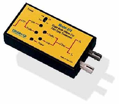
Model
374 10Base-T to Single Mode Fiber
Optic Transceiver
This
unit is pictured in Figure
4-7. It is the almost the
same as the Model 373 except
that its fiber
optic
components
are adapted for single-mode
transmission. Because single mode
fiber optic cable has
much
lower
attenuation this allows a
significant extension of distance. In
fact, the Model 374 10Base-T
to
Single-Mode
Fiber Optic Transceiver
extends the distance of a 10Base-T
Ethernet LAN to over 14
km.
The
ability to achieve the
extended distance is due to full duplex
transmission. Full-Duplex* has
one
important
advantage. Since there are separate
transmit and receive paths, DTE's can
transmit and receive
at
the same time. Collisions
are therefore eliminated.
Full Duplex Ethernet is a
collision free
environment.
For
single-mode fiber optic cable
transmission there is no standard
comparable to 10Base-FL.
*Duplex
operation - Transmission on a data
link in both directions.
Half duplex refers to
such
transmission,
but in a time-shared mode-
only one direction can transmit at a
time. With full
duplex
there
can be transmission in both direction
simultaneously.
Page
55 of 97
Figure
4-7: Model 374 10Base-T to
Single Mode Fiber Optic
Transceiver.
The
application illustrated in Figure
4-6 also applies to the Model
374. However, now
our
manufacturing
manager can be located in a building as
far as 14 km away from the
Accounting
Department
and still be tied into their
10Base-T Ethernet LAN.
The
Model 375
100Base-T to Multimode Fiber Optic
Transceiver allows
any two 100Base-TX
compliant
ports to be connected by multimode,
62.5/125 micron fiber optic
cable, while assuring
that
collision
information is preserved and translated
from one segment to the other.
The operation of the
device
is transparent to the network and is
offered in two versions. The
Model 375ST is equipped
with
ST
fiber connectors and offers 2 Km
performance.
The
100 BASE-T adapters allow full
duplex, simultaneous transfer of
data with a minimum
of
collisions.
The Model 375 extends this
full duplex capability using
dual fibers, while offering
flawless
data
transmission at 100 MBPS. The
Model 375 incorporates three
LED's that report if the 100
Base-T
and
fiber are active and
powered. The fiber optic
connector is a duplex as ordered,
designed for
operation
at 100 MBPS for FDDI, ATM or
Fast Ethernet. Power for
the Model 375 is via a
supplied
power
pack.
Table of Contents:
- Introduction:The Fundamental Problem of Communication, Program
- The Fiber Optic Data Communications Link For the Premises Environment:Fiber Optic Cable
- Exploiting The Bandwidth Of Fiber Optic Cable-Employment by Multiple Users:Sharing the Transmission Medium
- Exploiting The Delay Properties Of Fiber Optic Cable For LAN Extension:Brief History of Local Area Networks
- Exploiting The Advantages Of Fiber Optic Cable In the Industrial Environment:The Problem of Interference
- Serial Data Communications Over Fiber Optic Cable
- Standards
- Glossary