 |
Page
38 of 97
EMPLOYMENT
BY MULTIPLE USERS
3.1
Sharing the Transmission
Medium
You
are the network manager of a
company. You have a Source-User
link requirement given to
you. In
response
you install a premises fiber
optic data link. The
situation is just like that
illustrated in Figure 2-
1.
However, the bandwidth
required by the particular
Source-User pair, the
bandwidth to accommodate
the
Source-User speed requirement, is
much, much, less than is
available from the fiber
optic data link.
The
tremendous bandwidth of the
installed fiber optic cable is
being wasted. On the face of it,
this is not
an
economically efficient
installation.
You
would like to justify the
installation of the link to
the Controller of your
company, the person
who
reviews
your budget. The Controller
doesn't understand the attenuation
benefits of fiber optic cable.
The
Controller
doesn't understand the interference
benefits of fiber optic cable.
The Controller hates
waste.
He
just wants to see most of
the bandwidth of the fiber
optic cable used not wasted.
There is a solution
to
this problem. Don't just
dedicate the tremendous
bandwidth of the fiber optic
cable to a single,
particular,
Source-User communication requirement.
Instead, allow it to be shared by a
multiplicity of
Source-User
requirements. It allows it to carve a
multiplicity of fiber optic
data links out of the
same
fiber
optic cable.
The
technique used to bring
about this sharing of the
fiber optic cable among a
multiplicity of Source-
User
transmission requirements is called
multiplexing. It is not particular to
fiber optic cable. It
occurs
with
any transmission medium e.g.
wire, microwave, etc., where
the available bandwidth far
surpasses
any
individual Source-User requirement.
However, multiplexing is particularly
attractive when the
transmission
medium is fiber optic cable.
Why? Because the tremendous
bandwidth presented by
fiber
optic
cable presents the greatest
opportunity for sharing
between different Source-User
pairs.
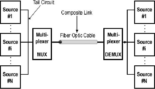
Conceptually,
multiplexing is illustrated in Figure
3-1. The figure shows
'N' Source-User pairs
indexed
as
1, 2, . . . There is a multiplexer
provided at each end of the
fiber optic cable. The
multiplexer on the
left
takes the data provided by
each of the Sources. It combines
these data streams together
and sends
the
resultant stream out on the
fiber optic cable. In this
way the individual Source
generated data
streams
share
the fiber optic cable. The
multiplexer on the left
performs what is called a
multiplexing or
combining
function. The multiplexer on
the right takes the
combined stream put out by
the fiber optic
cable.
It separates the combined stream
into the individual Source
streams composing it. It
directs each
of
these component streams to
the corresponding User. The
multiplexer on the right
performs what is
called
a demultiplexing function.
A
few things should be noted
about this illustration
shown in Figure 3-1.
Page
39 of 97
Figure
3-1: Conceptual view of
Multiplexing. A single fiber
optic cable is "carved" into a
multiplicity of fiber optic
data
links.
First,
the Transmitter and Receiver
are still present even
though they are not
shown. The Transmitter
is
considered
part of the multiplexer on
the left and the Receiver is
considered part of the multiplexer
on
the
right.
Secondly,
the Sources and Users are
shown close to the multiplexer.
For multiplexing to make sense
this
is
usually the case. The
connection from Source-to-multiplexer and
multiplexer-to-User is called a
tail
circuit.
If the tail circuit is too
long a separate data link
may be needed just to bring
data from the Source
to
the multiplexer or from the
multiplexer to the User. The
cost of this separate data
link may counter
any
savings effected by
multiplexing.
Thirdly,
the link between the
multiplexer, the link in
this case realized by the
fiber optic cable, is
termed
the
composite link. This is the
link where traffic is
composed of all the separate
Source streams.
Finally,
separate Users are shown in
Figure 3-1. However, it may
be that there is just one
User with
separate
ports and all Sources are
communicating with this
common user. There may be
variations upon
this.
The Source-User pairs need
not be all of the same
type. They may be totally
different types of
data
equipment
serving different applications and
with different speed
requirements.
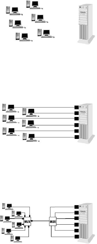
Within
the context of premise data
communications a typical situation
where the need for
multiplexing
arises
is illustrated in Figure 3-2.
This shows a cluster of
terminals. In this case
there are six
terminals.
All
of these terminals are
fairly close to one another. All are at a
distance from and want to
communicate
with
a multi-user computer. This
may be either a multi-use PC or a
mini-computer. This situation
may
arise
when all of the terminals
are co-located on the same
floor of an office building and
the multi-user
computer
is in a computer room on another
floor of the
building.
The
communication connection of each of
these terminals could be
effected by the approach
illustrated
in
Figure 3-3. Here each of
the terminals is connected to a
dedicated port at the
computer by a separate
cable.
The cable could be a twisted
pair cable or a fiber optic cable. Of
course, six cables are
required
Page
40 of 97
and
the bandwidth of each cable
may far exceed the
terminal-to-computer speed
requirements.
Figure
3-2: Terminal cluster
isolated from multi-user
computer
Figure
3-3: Terminals in cluster.
Each connected by dedicated cables to
multi-user computer
Figure
3-4: Terminals sharing a
single cable to multi-user computer by
multiplexing
Page
41 of 97
A
more economically efficient
way of realizing the
communication connection is shown in
Figure 3-4.
Here
each of the six terminals is
connected to a multiplexer. The
data streams from these
terminals are
collected
by the multiplexer. The
streams are combined and
then sent on a single cable to
another
multiplexer
located near the multi-user
computer. This second
multiplexer separates out
the individual
terminal
data streams and provides
each to its dedicated port.
The connection going from
the computer
to
the terminals is similarly
handled. The six cables
shown in Figure 3-3 has
been replaced by the
single
composite
link cable shown in Figure
3-4. Cable cost has been
significantly reduced. Of course,
this
comes
at the cost of two multiplexers.
Yet, if the terminals are in
a cluster the tradeoff is in
the direction
of
a net decrease in
cost.
There
are two techniques for
carrying out multiplexing on
fiber optic cable in the premise
environment.
These
two techniques are Time
Division Multiplexing (TDM) and
Wavelength Division
Multiplexing
(WDM).
These techniques are described in
the sequel. Examples are
introduced of specific products
for
realizing
these techniques. These products
are readily available from
Telebyte. TDM and WDM are
then
compared.
3.2
Time Division Multiplexing (TDM)
with Fiber Optic
Cable
With
TDM a multiplicity of communication
links, each for a given
Source-User pair, share the
same
fiber
optic cable on the basis of
time. The multiplexer(s) set
up a continuous sequence of time
slots
using
clocks. The duration of the
time slots depends upon a
number of different engineering
design
factors;
most notably the needed
transmission speeds for the
different links. Each communication
link is
assigned
a specific time slot, a TDM
channel, during which it is
allowed to send its data
from the Source
end
to the User end. During
this time slot no other
link is permitted to send
data. The multiplexer at
the
Source
end takes in data from the
Sources connected to it. It
then loads the data from
each Source into
its
corresponding TDM channel. The
multiplexer at the User end
unloads the data from
each channel
and
sends it to the corresponding
User.
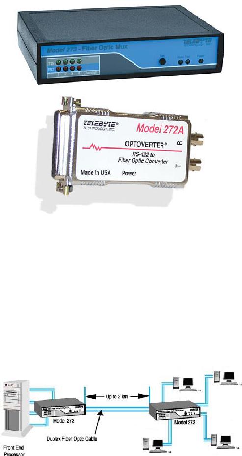
As
an example, the Telebyte
Model 273 is a high performance
four-channel, time division
multiplexer
whose
composite link is implemented in
fiber optics. The Model 273
will transport four
full-duplex
channels
of asynchronous RS-232 data
over two fiber optic cables.
In addition, a bi-directional
control
signal
is also transmitted for each of
the four primary channels.
The maximum rate for all
four channels
is
256 KBPS, 64 KBPS each. A
jumper option allows
upgrading channel 1 to 128 KBPS
while reducing
the
total channel capacity from
four to three. As an aid to installation
and verification of system
performance
the Model 273 is equipped with a
front panel TEST switch.
The function of this switch
is
to
send a test pattern to the
remote Model 273, which
causes it to go into loopback. A
SYNC LED
indicates
status of the fiber optic
link. Signals on the RS-232
data lines are monitored
via the four
Transmit
Data LED's and the four
Receive Data LED's. Power
for the Model 273 is
supplied by a small
power
adapter. Each Model 273 is supplied with
four pieces of modular cable and
eight RS-232
adapters.
These adapters, four male and
four female, offer users
the ability to provide any
connection
required
by their RS-232
interfaces.
Page
42 of 97
Figure
3-5: Model 273 Four
channel fiber optic TDM
Multiplexer with Model 272A
Fiber Optic Line Driver, a
copper to
fiber
converter.
The
illustration Figure 3-6
shows an application of the
Telebyte Model 273 Four
Channel Fiber Optic
Multiplexer.
On the right side are
four (4) different data
devices. These are of different types,
PCs and
terminals.
All of these data devices need to
communicate with a main
frame computer. This is
not
shown
but what is shown on the
left is the Front End
Processor (FEP) of this main
frame computer. All
communication
to/from the main frame
computer is through ports of
the FEP. Each data device
is
assigned
a dedicated port at the FEP.
The two Model 273's
effect the communication
from/to all these
devices
by using just one fiber
optic cable that can be as long as 2
km.
Figure
3-6: Model 273 realizing
time division multiplexed
data communications to a mainframe
computer through its
FEP.
Page
43 of 97
When
dealing with copper to fiber
connections, an interface converter
such as the Model 272A
provides
the
capability of performing an interface
conversion between full duplex,
RS-422 signals and
their
equivalent
for fiber optic
transmission. For applications
where the transmission
medium must be
protected
from electrical interference,
lightning, atmospheric conditions or
chemical corrosion
fiber
optics
is the perfect solution. The
Model 272A RS-422 to Fiber
Optic Line Driver handles
full duplex
data
rates to 2.5 MBPS. The
electrical interface to the
RS-422 port is fully differential
for transmit and
receive
data and is implemented in an industry
standard DB25 connector. The
fiber optic ports
are
implemented
using the industry standard ST
connectors. The design has
been optimized for
62.5/125
micron
fiber cable, however other
sizes may be used. The
optical signal wavelength is
approximately
850nm.
The optical power budget
for the Model 272A is 12
dB. In normal applications
the distance
between
a pair of Model 272A's will be at least 2
km (6,600 ft). Power to
operate the Model 272A
is
supplied
by a small, wall mounted, 9
Volt AC transformer and line
cord.
3.3
Wavelength Division Multiplexing (WDM)
With Fiber Optic
Cable
With
WDM a multiplicity of communication
links, each for a given
Source-User pair, share the
same
fiber
optic cable on the basis of
wavelength. The data stream
from each Source is assigned an
optical
wavelength.
The multiplexer has within
it the modulation and transmission
processing circuitry. The
multiplexer
modulates each data stream
from each Source. After the
modulation process the
resulting
optical
signal generated for each
Source data stream is placed on its
assigned wavelength.
The
multiplexer
then couples the totality of
optical signals generated
for all Source data streams
into the fiber
optic
cable. These different wavelength optical
signals propagate simultaneously.
This is in contrast to
TDM.
The
fiber optic cable is thereby
carved into a multiplicity of
data links - each data
link corresponding to
a
different one of these optical
wavelengths assigned to the
Sources.
At
the User end the multiplexer
receives these simultaneous optical
signals. It separates these
signals out
according
to their different wavelengths by
using prisms. This
constitutes the demultiplexing
operation.
The
separated signals correspond to
the different Source-User
data streams. These are
further
demodulated.
The resulting separated data
streams are then provided to
the respective Users.
At
this point a slight
digression is necessary. The focus of
this book is on premise data
communications,
data
communications in the local
area environment. Notwithstanding, it
must be mentioned that
WDM
has
been receiving a tremendous
amount of attention within
the context of Wide Area
Networks
(WANs).
Both CATV systems and telecommunication
carriers are making greater and greater
use of it
to
expand the capacity of the
installed WAN fiber optic
cabling plant. Within the
Wide Area
Networking
environment the multiplicity of
channels carved from a
single fiber has
increased
tremendously
using WDM. The increase has
led to the term Dense
Wavelength Division
Multiplexing
(DWDM)
to describe the newer WDMs
employed. Now, back to our
main topic.
3.4
Comparing Multiplexing Techniques
for the Premises
Environment
It
is best to compare TDM and WDM on the
basis of link design flexibility,
speed and impact on
BER.
Link
Design Flexibility - TDM can be engineered to
accommodate different link types. In
other words, a
TDM
scheme can be designed to carve a
given fiber optic cable into
a multiplicity of links
carrying
different
types of traffic and at different
transmission rates. TDM can also be engineered to
have
different
time slot assignment strategies.
Slots may be permanently
assigned. Slots may be
assigned
Page
44 of 97
upon
demand (Demand Assignment Multiple
Access - DAMA). Slots may
vary depending upon
the
type
of link being configured.
Slots may even be dispensed
with altogether with data
instead being
encapsulated
in a packet with Source and User
addresses (statistical multiplexing).
However, within the
context
of premises environment there is
strong anecdotal evidence
that TDM works best when it
is used
to
configure a multiplicity of links
all of the same traffic
type, with time slots
all of the same
duration
and
permanently assigned. This
simplest version of TDM is easiest to
design and manage in premise
data
communications. The more
complex versions are really
meant for the WAN
environment.
On
the other hand, in the
premises environment WDM, generally,
has much greater flexibility. WDM
is
essentially
an analog technique. As a result,
with WDM it is much easier to
carve a fiber optic cable
into
a
multiplicity of links of quite
different types. The
character of the traffic and
the data rates can be
quite
different
and not pose any real
difficulties for WDM. You can mix
10Base-T Ethernet LAN traffic
with
100Base-T
Ethernet LAN traffic with
digital video and with out
of band testing signals and so on.
With
WDM
it is much easier to accommodate analog
traffic. It is much easier to
add new links on to
an
existing
architecture. With TDM the
addition of new links with
different traffic requirements
may
require
revisiting the design of all
the time slots, a major
effort.
With
respect to flexibility the one
drawback that WDM has
relative to TDM in the
premises
environment
is in the number of simultaneous
links it can handle. This is
usually much smaller
with
WDM
than with TDM. Nonetheless,
advances in DWDM for the WAN
environment may filter down
to
the
premise environment and reverse this
drawback.
Speed
- Design of TDM implicitly depends
upon digital components.
Digital circuitry is required to
take
data
in from the various Sources.
Digital components are
needed to store the data.
Digital components
are
needed to load the data
into corresponding time
slots, unload it and deliver it to
the respective Users.
How
fast must these digital
components operate? Roughly,
they must operate at the
speed of the
composite
link of the multiplexer.
With a fiber optic cable
transmission medium, depending
upon cable
length,
a composite link of multiple GBPS
could be accommodated. However,
commercially available,
electrically
based, digital logic speeds
today are of the order of 1
billion operations per second. This
can
and
probably will change in the future as
device technology continues to progress.
But, let us talk in
terms
of today. TDM is really speed
limited when it comes to
fiber optic cable. It can not
provide a
composite
link speed to take full advantage of the
tremendous bandwidth presented by
fiber optic cable.
This
is not just particular to
the premises environment it also applies
to the WAN environment.
On
the other hand, WDM does
not have this speed
constraint. It is an analog technique.
Its operation
does
not depend upon the
speed of digital circuitry. It can
provide composite link
speeds that are in
line
with
the enormous bandwidth
presented by fiber optic
cable.
Impact
on BER - Both TDM and WDM, carve a
multiplicity of links from a
given fiber optic
cable.
However,
there may be cross talk
between the links created.
This cross talk is
interference that can
impact
the BER and affect the
performance of the application
underlying the need for
communication.
With
TDM cross-talk arises when
some of the data assigned to
one time slot slides into an
adjacent time
slot.
How does this happen? TDM
depends upon accurate clocking.
The multiplexer at the Source
end
depends
upon time slot boundaries
being where they are
supposed to be so that the
correct Source data is
loaded
into the correct time
slot. The multiplexer at the
User end depends upon time
slot boundaries
being
where they are supposed to
be so that the correct User
gets data from the
correct time slot.
Accurate
clocks are supposed to
indicate to the multiplexer
where the time slot
boundaries are.
However,
clocks drift, chiefly in
response to variations in environmental
conditions like
temperature.
What
is more, the entire
transmitted data streams, the
composite link, may shift
small amounts back and
forth
in time, an effect called
jitter. This may make it
difficult for the
multiplexer at the User end
to
Table of Contents:
- Introduction:The Fundamental Problem of Communication, Program
- The Fiber Optic Data Communications Link For the Premises Environment:Fiber Optic Cable
- Exploiting The Bandwidth Of Fiber Optic Cable-Employment by Multiple Users:Sharing the Transmission Medium
- Exploiting The Delay Properties Of Fiber Optic Cable For LAN Extension:Brief History of Local Area Networks
- Exploiting The Advantages Of Fiber Optic Cable In the Industrial Environment:The Problem of Interference
- Serial Data Communications Over Fiber Optic Cable
- Standards
- Glossary