 |
Page
56 of 97
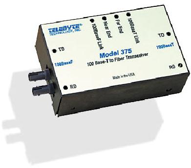
Figure
4-8: Model 375 100Base-T to
Fiber Transceiver for Fast
Ethernet
The
application illustrated in Figure
4-6 applies to the Model
375. You merely have to
substitute a Fast
Ethernet,
100Base-T Ethernet LAN, for
the 10Base-T Ethernet LAN and
substitute a Model 375 for
the
Model
373.
CHAPTER
5
EXPLOITING
THE ADVANTAGES OF FIBER OPTIC CABLE IN THE
INDUSTRIAL
ENVIRONMENT
5.1
Data Communications in the Industrial
Environment
Our
attention is now drawn to
the problem of data
communications in the industrial
environment. This is
the
problem of data communications in
the manufacturing facility. It is
the problem of data
communications
on the factory floor or in
the process control plant.
Data communications in these
premises
can significantly benefit by using
fiber optic cable as the
Transmission Medium.
Let
us begin by describing the
industrial environment from a
data communications
perspective.
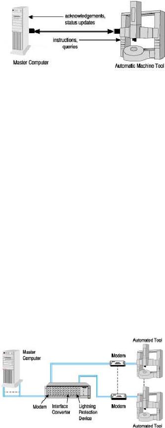
What
type of data communications is
going on here? Typically,
the situation is illustrated in
Figure 5-1.
There
is a Master Computer located
somewhere in the manufacturing
facility. In the past this
was
usually
a mini-computer. Presently, it is either
a workstation or PC. The
Master Computer is
communicating
with any of a number of data
devices. For example, it may be
controlling automated
tools
and sensors. It may also be exercising
control by querying and receiving
data from different
monitors.
These data devices are located
throughout the facility. The
illustration provided by Figure
5-1
shows
a machine tool, but in
actuality the number of
different automated tool
types, sensors and
monitors
may be very large. By way of
example, it may extend to
well over 100 in a
semiconductor
Page
57 of 97
fabrication
facility.
The
control procedure exercised by the
Master Computer usually consists of
sending a message out
and
receiving
a message back. It may be
sending automated tool or
sensor an instruction. It may
then receive
back
either an acknowledgement of instruction
receipt or a status update of some sort.
In like manner,
the
Master Computer may send
queries to a monitor and receive back status
updates.
Figure
5-1: Data Communications in
the industrial
environment
As
is readily evident, the
whole control procedure is
executed using data
communications with
appropriate
signaling devices (modems) and other
needed equipment located at
both the Master
Computer
and the data device
locations. Required data
transmission rates need not
be significantly large.
On
the other hand, in the
industrial environment reliability
requirements are quite
stringent. This is so
regardless
of whether reliability is measured by
either BER or link up-time
or some other
parameter.
The
consequences of an unreliable data
communications link may be a mere
annoyance when it
comes
to
office communications. However,
consequences may be catastrophic in a
manufacturing operation.
Literally,
an unreliable link could close
down a whole plant.
Generally,
the type of situation
described above leads the
data communications in the
industrial
environment
to follow an inherently hierarchical
architecture. This type of
architecture is shown in
Figure
5-2. The Master Computer is
located near a communications closet.
The modems and/or
other
communications
equipment (e.g., surge suppressors,
isolators, interface converters)
needed by the
Master
Computer to effect links to
the data devices are usually
rack-mounted in a card cage placed in
the
communications
closet. Cabling then extends
out from the card cage to
the individual data devices.
At
the
data device end the matching
communications equipment may
either be stand-alone or DIN
Rail
mounted.
With the latter, the
communications equipment snap
onto a rail mounted on a
wall or mounted
on
some convenient cabinet near
the data device. DIN Rail
mounting will be discussed in greater
detail
toward
the end of this
chapter.
Page
58 of 97
Figure
5-2: Data communications
architecture usually found in the
industrial environment
It
is important to note that
this is the general case
not the absolute case. If
the Master Computer has
just
1
or a few ports there may be
no need for a card cage. All
data communications equipment
may then be
of
the stand-alone type.
There
are several topologies
associated with this type of
hierarchical architecture. The
topology could be
a
star with a cable extending out
from the card cage hub to
each data device. Each ray
of the star is
simultaneously
operating as data communications
link. The topology could be
a multi-dropped daisy
chain,
using the RS-485 interface
standard. This is particularly suited to
a polling, query-response,
data
communications
scheme - the type of
communications being carried
out by the Master Computer.
The
topology
could even be a broadcast
bus, the type used by an
Ethernet LAN.
5.2
The Problem of
Interference
In
considering data communications in
the industrial environment a
key concern is the problem
of
interference.
This is an underlying concern
regardless of whether or not
the architecture is
hierarchical
or
not and regardless of what
topology is employed.
From
an interference point of view
the manufacturing facility
represents a stressed environment.
The
presence
of high current equipment
such as the automated tools
results in the propagation
of
electromagnetic
pulses that interfere with
the data communications
links. Proper grounding is
always
difficult
in the industrial environment.
Ground loops and resulting
ground currents can cause
transmitted
data
to be demodulated in error.
In
the past, UTP copper cable was
the transmission medium of
choice for the industrial
environment.
Why?
Principally, because of there was a
lot of experience in dealing with
it. There are a number
of
different
ways of handling the problem
of intense interference when
UTP copper cable is employed in
this
environment. Sponges can be inserted
into a data communications
link to protect against surges.
Isolators
can be inserted into a data
communications link to protect against
ground loops. Single
ended
serial
communications can be replaced with
serial communications employing
differential signaling
based
upon the RS-422 standard.
Differential signaling, with
sufficient balance, allows
electromagnetic
interference
of the type prevalent on the
factory floor, to cancel
itself during the data
communications
reception.
But
what about fiber optic cable
as the Transmission Medium, doesn't
this have great
interference
protection?
Good point! If fiber optic
cable is employed in the industrial
environment concerns
about
interference
can vanish. This Transmission
Medium is simply not
affected by the
electromagnetic
interference
plaguing the factory floor.
Furthermore, there is a side
benefit. It was mentioned that
data
transmission
rate requirements are usually modest.
However, this may not
always be so. Using
fiber
optic
cable eliminates the concern
about future bandwidth
needs.
Fiber
optic cable as a Transmission Medium
has been slow in coming to
the industrial
environment.
This
has been principally due to
cost. However, this is
changing as the price of
fiber optic cable
steadily
decreases.
There
are two possible ways by
which fiber optic cable
based data communications
may be introduced
Page
59 of 97
into
a given manufacturing facility. In
the first way, a fiber
optic cable based network
may be introduced
from
the ground up. In other
words, it is installed where no
network previously existed in
the facility. In
the
second way, fiber optic
cabling may be patched into a
network already installed, a
pre-existing
network
that was based on UTP copper
cable.
Today,
if you are considering
installing a network from
the ground up then you
are talking about
installing
an Ethernet LAN with a fiber
optic cable Transmission Medium. In
the past, token ring
LANs
were
quite popular in factory
settings. They guaranteed maximum
transmission delays and
were
matched
to polling techniques. However,
lately Ethernet has come to
dominate even the
industrial
environment.
Furthermore, there is the advantage of
being able to bridge the
factory floor LAN to
other
Ethernet
based LANs in your
organization.
If
you are installing fiber
optic cable by patching into a
pre-existing UTP copper based
network then you
must
deal with the different
types of data interfaces
that may exist in that
network. These data
interfaces
may
include RS-232, RS-422 and
RS-485. Electrical representations of
data from/to these
interfaces
have
to be converted to/from light pulses
traveling down fiber optic
cable.
5.3
Fiber Optic Data Communications
Products that Can
Help
Telebyte
offers a number of different
products that are well
suited to providing data
communications in
the
industrial environment. These products
are particularly well suited
to the second approach
described
above,
the case where a fiber
optic cable capability is being patched
into a previously existing
UTP
copper
cable network. Several of these will
now be described now.
The
fiber optic cable multiplexer
discussed in Chapter 3 and the
Ethernet LAN Extenders discussed
in
Chapter
4 can be also be used to implement data
communications on the factory
floor. A multiplexer can
be
used to allow the Master
Computer to reach to different automated
tools/sensors/monitors with a
single
fiber optic cable. However,
the cost saving that they
can realize depends upon how
the
tools/sensors/monitors
are clustered. The LAN
Extenders can be used to realize a
total Ethernet LAN
approach
to the problem of data
communications in this
environment.
Model
271 Fiber Optic Auto Powered
Line Driver
Page
60 of 97
Figure
5-3: Model 271 Fiber
Optic Auto Powered Line
Driver
The
Model 271 Fiber Optic Auto
Powered Line Driver is a short
haul modem that employs an
RS-232
data
interface and transmits the
data onto a fiber optic
cable. This modem provides full
duplex,
asynchronous,
data communications over two
fiber optic cables. The
length of the fiber optic
cable can
be
up to 2 km and the data rate as high as
56 KBPS. Performance of the
unit is optimized for
62.5/125-
fiber
optic cable. However, the
modem can also be used with
fiber optic cable having
other dimensions.
The
operating power for the
Model 271 Fiber optic Auto
Powered Line Driver is derived
from the
transmit
data line. This is a real
convenience when an electrical
outlet is not readily
available. The
Model
271 is equipped with a DTE/DCE switch
that reverses pins 2 and 3 of
the RS-232 connector.
This
allows
the modem to support
terminals, printers, computers or
any other RS-232 based
device. The fiber
port
of the unit employs ST
connectors.
One
application of the Model 271 is
illustrated in Figure 5-4.
Notice while this
application deals with
the
factory
environment there is no card cage
shown. Rather, the
application deals with the
situation where
there
is the need for a data
communication link between a
mini-computer located in the
front office of a
company
and a PC located on the company's
factory floor. Both the
front office and the factory
floor are
in
the same building.
Page
61 of 97
Figure
5-4: Example application for
the Model 271
Data
communications carried out
strictly in the front office
may be quite reliable over
UTP copper
cable.
However, in this application
the data link traverses the
boundary to the factory
floor.
Consequently,
there is a need for the
extra reliability provided by
fiber optic cable.
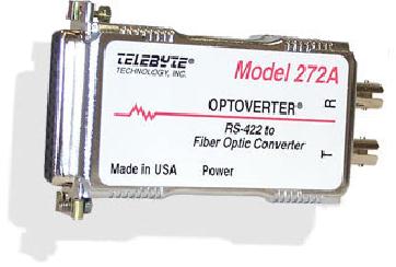
Model
272A RS-422 to Fiber Optic
Converter
The
Model 272A provides the
capability of performing an interface
conversion between full duplex,
RS-
422
signals and their equivalent
for fiber optic
transmission. For applications
where the
transmission
medium
must be protected from
electrical interference, lightning,
atmospheric conditions or
chemical
corrosion
fiber optics is the perfect
solution. The Model 272A
RS-422 to Fiber Optic Line
Driver
handles
full duplex data rates to
2.5 MBPS. The electrical
interface to the RS-422 port
is fully
differential
for transmit and receive
data and is implemented in an industry
standard DB25 connector.
The
fiber optic ports are
implemented using the
industry standard ST connectors. The
design has been
optimized
for 62.5/125 micron fiber
cable, however other sizes
may be used. The optical
signal
wavelength
is approximately 850nm. The
optical power budget for
the Model 272A is 12 dB. In
normal
applications
the distance between a pair of
Model 272A's will be at least 2 km (6,600
ft). Power to
operate
the Model 272A is supplied
by a small, wall mounted, 9
Volt AC transformer and line
cord.
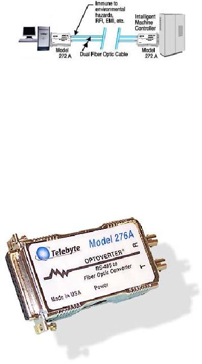
Figure
5-5: Model 272A RS-422 to
Fiber Optic
Converter
One
application of the Model
272A is illustrated in Figure
5-6. This is a simple case
of a single data
communications
link being required on the
factory floor. To avoid
complexities there is no card
cage
although
the extrapolation to one is quite
easy for the reader to
see. The link is between a
PC and an
Intelligent
Machine Controller. Previously,
the link was using RS-422
signaling for
protection.
Consequently,
the data interfaces of both
the PC and the Intelligent
Machine Controller have
RS-422
implemented
with DB25 connectors. The
Model 272A is placed at both
ends of the link and allows
the
data
communications to proceed using
fiber optic cable with its
much greater protection
from
interference.
Page
62 of 97
Figure
5-6: Example application for
the Model 272A
Model
276A - RS-485 to Fiber Optic
Converter
The
Model 276A RS-485 to Fiber
Optic Line Converter accepts
half-duplex data at rates up to 1
MBPS
through
an RS-485 interface. It then
transmits this data onto a
fiber optic cable. Likewise
the unit is able
to
receive data from a fiber
optic cable and send it to a device
through an RS-485 interface.
The RS-485
interface
used by this model is balanced and
implemented in a female DB25
connector.
Figure
5-7: Model 276A - RS-485
Fiber Optic
Converter
The
network architect specifies the
control of data flow in any
RS-485 based communications
facility.
The
Model 276 RS-485 to Fiber
Optic Line Driver provides
the network architect with
the greatest
versatility
by enabling the RS-485
transmitter when data is
detected at the fiber optic
receiver.
In
the Model 276A RS-485 to
Fiber Optic Converter the
fiber optic ports are
implemented using ST
connectors.
Performance is optimized for
fiber optic cable having
dimensions 62.5/125 and for
an
optical
signal with an 830 nm wavelength.
However, fiber optic cable of
other dimensions can be
employed.
The unit provides reliable
communication over a distance of 2
km.
Page
63 of 97
One
application of the Model 276
RS-485 to Fiber Optic Line
Driver is illustrated in Figure
5-8. This is
a
situation in which a PC on the
factory floor is controlling an
environmental control unit and a
number
of
different automated tools.
Control is exercised by communicating
commands and receiving
responses
through
an RS-485 polling network.
However, there is the
complication in that the PC
only has an RS-
232
interface. The environmental
control units and the
automated tools have RS-485
interfaces. The
enhanced
interference protection provided by
fiber optic cable is
required.
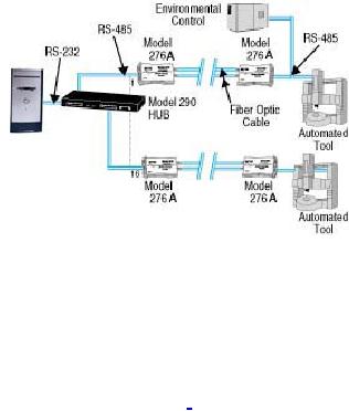
Figure
5-8: Example Application for
the Model 276A
In
this application the PC is
connected to the Telebyte
Model 290 RS-232 to
RS-422/RS-485
Concentrator
- Wiring Hub. This allows
conversion of communications from an
RS-232 interface to a
grouping
of both RS-422 and RS-485
interfaces. We are only interested in
the RS-485 ports of
the
Model
290. Data from/to the PC is
converted and is presented on these
RS-485 interfaces. Each of
these
interfaces
is then connected to a Model
276A RS-485 to Fiber Optic
Converter. The Model 276A
then
sends
this data out on a fiber
optic cable or receives the data
from a fiber optic cable. On
the far side of
each
of these fiber optic cables
is another Model 276A. This
takes the data from
the fiber optic cable
and
provides
it either to the environmental
control unit or to one of the
automated machine tools.
Likewise,
it
takes data from these and
transmits it back along a fiber
optic cable to the
PC.
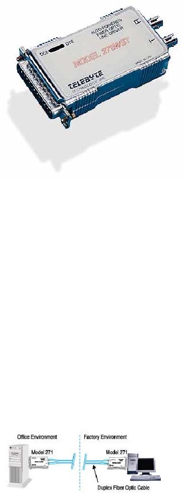
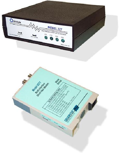
Model
277 RS-232, RS-422, RS-485 to
Multimode Fiber Optic Line
Driver
The
Model 277 Multi Interface
Fiber Optic Line Driver is
pictured as a stand-alone unit in
Figure 5-9.
Also
shown with it is the Model
8277. The Model 8277 is the
same as the Model 277 except
that it is
DIN
Rail mounted.
Page
64 of 97
Figure
5-9: The Model 277
and the Model 8277.
Both units are the
same except the Model 8277 is
DIN Rail
mountable.
The
Model 277 Multi Interface
Fiber Optic Line Driver is a
unique asynchronous fiber
optic modem.
The
optical interface can operate
either by a point-to-point or daisy
chain ring,
multi-drop,
configuration.
The electrical interface can also
operate in either a point-to-point or
multi-drop
configuration.
The network architect
selects the
configuration.
This
unit is appropriate for factory
floor networks where there
is an existing mixture of
point-to-point
and
multi-drop, UTP copper cable based
links. It can easily convert
them to fiber optic
operation with
the
added protection this
provides.
For
a point-to-point configuration, two
Model 277's are connected
back-to-back, to form a high
speed,
full
duplex, fiber optic
link.
In
an optical ring configuration,
three or more Model 277's, in
all 4-wire modes are
daisy chained in a
ring.
The ring will consist of a
Master Model 277 and two or
more slave Model 277's.
Master/slave
modes
are switch selectable. The slaves
pass the received optical
data along with the
transmit data from
their
own electrical interface to
their optical transmitters.
The Master does not
pass the received
optical
data.
A ring of up to 10 Model 277's at a
data rate of 1 MBPS can be formed. To
extend the optical
Page
65 of 97
distance
a pair of Model 277's can be
inserted into the optical
interface to act as a line
extender.
This
unit can support fiber optic
links as long as 1 mile with
a transmission rate as high as 1 MBPS.
The
design
is optimized for transmission
over multi-mode cable at a wavelength of
850 nm.
The
Model 277 electrical interface is
switch selectable between RS-232,
RS-422 and RS-485. As a
result,
this unit is well suited to
assisting in the evolution to fiber
optic cable of existing UTP
copper
cable
based factory networks.
Switch selection enables
data to flow from the
electrical interface
the
optical
transmitter or to be controlled by the
Request To Send (RTS)
line.
Full
duplex, four wire, or
half-duplex, four or two
wire, may be selected when
the RS-422 or RS-485
interface
is selected. The RS-422 or RS-485
interfaces of the Model 277
may operate in a
multi-dropped
or
point-to-point environment.
In
the half duplex mode,
the Model 277 controls the
transmit data line on the
electrical interface.
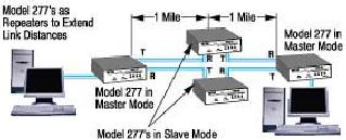
The
Model 277 is shown in an application in
Figure 5-11. Here several
Model 277's are being
employed
to
extend link length past 1
mile.
Figure
5-10: The Model 277
shown in application to extend
the link length
Model
9271 RS-232 Fiber Optic Auto
Powered Line
Driver
Model
9271 RS-232 Fiber Optic Auto
Powered Line Driver features a standard
DB9 interface for
maximum
performance and reliability of data
transmission over glass
fiber, eliminating the need
for
serial
to nine-pin adapters. In addition, it
brings effective data
communications to manufacturing
environments.
It can be installed in applications
requiring very high data
transmission rates,
offers
resistance
to Electromagnetic Interference (EMI),
and isolation from lightning-induced
current surges
and
ground loops. The unit
employs an RS-232 data
interface, can achieve 56 kbps
asynchronously and
operates
in either half- or full-duplex
modes over dual fibers up to
2 km in length.
Table of Contents:
- Introduction:The Fundamental Problem of Communication, Program
- The Fiber Optic Data Communications Link For the Premises Environment:Fiber Optic Cable
- Exploiting The Bandwidth Of Fiber Optic Cable-Employment by Multiple Users:Sharing the Transmission Medium
- Exploiting The Delay Properties Of Fiber Optic Cable For LAN Extension:Brief History of Local Area Networks
- Exploiting The Advantages Of Fiber Optic Cable In the Industrial Environment:The Problem of Interference
- Serial Data Communications Over Fiber Optic Cable
- Standards
- Glossary