 |
8
Building
an Outdoor Node
There
are many practical
considerations when installing
electronic equipment
outdoors.
Obviously, it has to be protected
from the rain, wind,
sun, and
other
harsh elements. Power needs
to be provided, and the
antenna should
be
mounted at a sufficient
height. Without proper
grounding, nearby
lightning
strikes,
fluctuating
mains power, and even a
light winds in the proper
climate
can
annihilate your wireless
links. This chapter will
give you some idea
of
the
practical problems you will
be up against when installing
wireless equip-
ment
outdoors.
Waterproof
enclosures
Suitable
waterproof enclosures come in
many varieties. Metal or
plastic may
be
used to create a watertight
container for outdoor
embedded equipment.
Of
course, equipment needs
power to work, and will
likely need to connect
to
an
antenna and Ethernet cable.
Each time you pierce a
watertight enclosure,
you
provide another potential
place for water to seep
in.
The
National Electrical Manufacturers
Association (NEMA) provides
guidelines
for
protection of electrical equipment
from rain, ice, dust,
and other contami-
nants.
An enclosure with a rating of
NEMA
3 or better is
suitable for outdoor
use
in a fair climate. A NEMA
4X or
NEMA
6 provides
excellent protection,
even
from hose driven water
and ice. For fixtures
that pierce the body of
an
enclosure
(such as cable glands and
bulkhead connectors), the International
Electrotechnical
Commission (IEC) assigns an
ingress protection (IP)
rating.
An
ingress protection rating of
IP66
or
IP67
will
protect these holes from
very
strong
jets of water. A good
outdoor enclosure should
also provide UV protec-
249
250
Chapter
8: Building an Outdoor
Node
tion
to prevent breakdown of the
seal from exposure to the
sun, as well as to
protect
the equipment inside.
Of
course, finding
NEMA or IEC rated enclosures
may be a challenge in
your
local
area. Often, locally
available parts can be
repurposed for use as
enclo-
sures.
Rugged plastic or metal
sprinkler boxes, electrical
conduit housings,
or
even plastic food containers
can be used in a pinch. When
piercing an
enclosure,
use quality gaskets or
o-rings along with a cable
gland to seal the
opening.
UV stabilized silicone compound or
other sealant can be used
for
temporary
installations, but remember
that cables flex in the
wind, and glued
joints
will eventually weaken and
allow moisture to seep
in.
You
can greatly extend the
life of a plastic enclosure by
providing some pro-
tection
from the sun. Mounting
the box in the shade,
either beneath
existing
equipment,
solar panel, or thin sheet
of metal specifically
for this purpose,
will
add to the life span of
the box as well as the
equipment contained
inside.
Before
putting any piece of
electronics in a sealed box, be
sure that it has
minimal
heat dissipation requirements. If
your motherboard requires a
fan or
large
heat sink, remember that
there will be no airflow,
and your electronics
will
likely bake to death on the
tower. Only use electronic
components that
are
designed to be used in an embedded
environment.
Providing
power
Obviously,
DC power can be provided by
simply poking a hole in your
enclo-
sure
and running a wire. If your
enclosure is large enough
(say, an outdoor
electrical
box) you could even
wire an AC outlet inside the
box. But manu-
facturers
are increasingly supporting a
very handy feature that
eliminates the
need
for an additional hole in
the box: Power
over Ethernet (POE).
The
802.3af standard defines a
method for supplying power
to devices using
the
unused pairs in a standard
Ethernet cable. Nearly 13
Watts of power can
be
provided safely on a CAT5
cable without interfering
with data transmis-
sions
on the same wire. Newer
802.3af compliant Ethernet
switches (called
end
span injectors) supply
power directly to connected
devices. End span
switches
can supply power on the
same wires that are
used for data (pairs
1-
2
and 3-6) or on the unused
wires (pairs 4-5 and
7-8). Other
equipment,
called
mid
span injectors, are
inserted between Ethernet
switches and the
device
to be powered. These injectors
supply power on the unused
pairs.
If
your wireless router or CPE
includes support for
802.3af, you could in
the-
ory
simply connect it to an injector.
Unfortunately, some manufacturers
(no-
tably
Cisco) disagree on power
polarity, and connecting
mismatching gear
can
damage the injector and
the equipment to be powered.
Read the fine
Chapter
8: Building an Outdoor
Node
251
print
and be sure that your
injector and wireless
equipment agree on
which
pins
and polarity should be used
for power.
If
your wireless equipment
doesn t
support
power over Ethernet, you can
still use
the
unused pairs in a CAT5 cable to carry
power. You can either use a
passive
POE
injector, or simply
build one yourself. These
devices manually connect
DC
power
to the unused wires on one
end of the cable, and
connect the other end
directly
to a barrel connector inserted in the device
s power
receptacle. A pair of
passive
POE devices can typically be
purchased for under
$20.
To
make your own, you
will need to find out
how much power the
device re-
quires
to operate, and provide at
least that much current
and voltage, plus
enough
to account for loss in the
Ethernet run. You don
t want to
supply too
much
power, as the resistance of
the small cable can
present a fire
hazard.
Here
is an online calculator that
will help you calculate
the voltage drop for
a
given
run of CAT5 : http://www.gweep.net/~sfoskett/tech/poecalc.html
Once
you know the proper
power and electrical
polarity needed to
power
your
wireless gear, crimp a CAT5
cable only using the
data wires (pairs
1-2
and
3-6). Then simply connect
the transformer to pairs 4-5
(usually blue /
blue-white)
and 7-8 (brown /
brown-white) on one end, and
a matching barrel
connector
on the other.
Mounting
considerations
In
many cases, equipment can be
located inside a building,
provided there is
a
window with ordinary glass
through which the beam
can travel. Normal
glass
will introduce little
attenuation, but tinted
glass will introduce
unaccept-
able
attenuation. This greatly
simplifies mounting,
power, and
weatherproof-
ing
problems, but is obviously
only useful in populated
areas.
When
mounting antennas on towers, it is very important to
use a stand off
bracket,
and
not mount the antennas directly to the tower. These
brackets help with many
functions
including antenna separation,
antenna alignment and
protection.
Stand
off brackets need to be
strong enough to support the
weight of the an-
tenna,
and also hold it in place on
windy days. Remember,
antennas can act
like
small sails, and can
put a lot of force on to
their mounts in strong
winds.
When
estimating wind resistance,
the total surface of the
antenna structure
must
be considered, as well as the
distance from the center of
the antenna to
the
point of attachment to the
building. Large antennas
such as solid dishes
or
high gain sectorial panels
can have considerable wind
load. Using a slot-
ted
or mesh parabolic, rather
than a solid dish, will
help reduce the wind
load
without
much affect on antenna gain.
Be sure that the mounting
brackets
252
Chapter
8: Building an Outdoor
Node
and
supporting structure are
solid, or your antennas will
become misaligned
over
time (or worse, fall
off the tower
entirely!)
Mounting
brackets must have enough
clearance from the tower to
allow for
aiming,
but not too much
clearance that the antennas
become too hard to
reach
if any service or maintenance is
required.
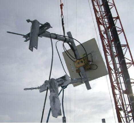
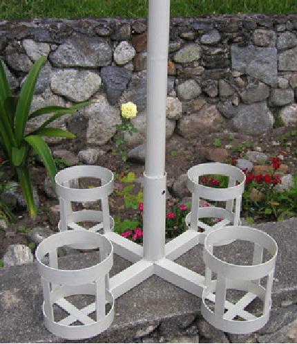
Figure
8.1: An antenna with a
standoff bracket being
lifted onto a
tower.
The
pipe on the standoff bracket
that the antenna will be
mounted on needs
to
be round. This way the
antenna can be pivoted on
the pipe for
aiming.
Secondly,
the pipe must also be
vertical. If it is being mounted on a
tapered
tower,
the standoff bracket will
have to be designed to allow
for this. This
can
be done using different
lengths of steel, or by using
combinations of
threaded
rod and steel
plates.
As
the equipment will be
outside for all of its
service life, it is important to
be
sure
that the steel used is
weatherproofed. Stainless steel
often has too
high
a
price tag for tower
installations. Hot galvanizing is
preferred, but may
not
be
available in some areas.
Painting all steel with a
good rust paint will
also
work.
If paint is chosen, it will be
important to plan a yearly
inspection of the
mount
and repaint when
necessary.
Chapter
8: Building an Outdoor
Node
253
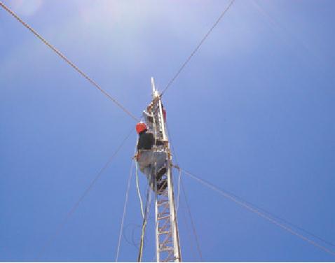
Guyed
towers
A
climbable guyed tower is an
excellent choice for many
installations, but
for
very
tall structures a self
supporting tower might be
required.
When
installing guyed towers, a
pulley attached to the top
of a pole will
facili-
tate
the tower installation. The
pole will be secured to the
lower section al-
ready
in place, while the two
tower sections are attached
with an articulated
joint.
A rope passing through the
pulley will facilitate the
raising of the next
section.
After the cantilever section
becomes vertical, bolt it to
the lower sec-
tion
of the pole. The pole
(called a gin pole in the
trade) can then be
re-
moved,
and the operation may be
repeated, if required. Tighten
the guy
wires
carefully, ensuring that you
use the same tension at
all suitable anchor-
ing
points. Chose the points so
that the angles, as seen
from the center of
the
tower, are as evenly spaced
as possible.
Figure
8.2: A climbable guyed
tower.
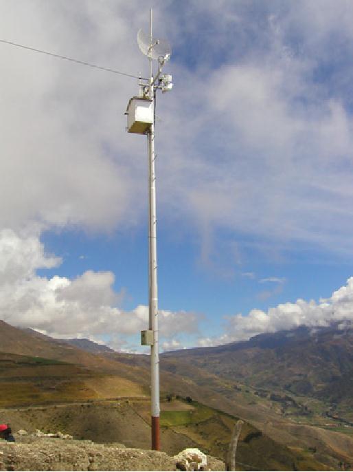
Self-supporting
towers
Self
supporting towers are
expensive but sometimes
needed, particularly
when
greater
elevation is a requirement. This
can be as simple as a heavy
pole
sunk
into a concrete piling, or as
complicated as a professional radio
tower.
254
Chapter
8: Building an Outdoor
Node
Figure
8.3: A simple self-supporting
tower.
An
existing tower can sometimes
be used for subscribers,
although AM
transmitting
station antennas should be
avoided because the whole
structure
is
active. FM station antennas
are acceptable, provided
that at least a few
of
meters
of separation is kept between
the antennas. Be aware that
while ad-
jacent
transmitting antennas may
not interfere with your
wireless connection,
high
powered FM may interfere
with your wired Ethernet
cable. Whenever
Chapter
8: Building an Outdoor
Node
255
using
a heavily populated antenna
tower, be very scrupulous
about proper
grounding
and consider using shielded
cable.
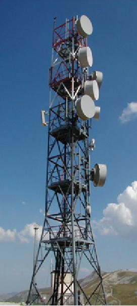
Figure
8.4: A much more complicated
tower.
Rooftop
assemblies
Non-penetrating
roof mount antenna
assemblies can be used on flat
roofs.
These
consist of a tripod mounted to a
metal or wooden base. The
base is
then
weighed down with bricks,
sandbags, water jugs, or
just about anything
heavy.
Using such a rooftop "sled"
eliminates the need to
pierce the roof
with
mounting
bolts, avoiding potential
leaks.
256
Chapter
8: Building an Outdoor
Node
Figure
8.5: This metal base
can be weighed down with
sandbags, rocks, or
water
bottles
to make a stable platform without
penetrating a roof.
Wall
mount or metal strap
assemblies can be used on
existing structures
such
as chimneys or the sides of a
buildings. If the antennas
have to be
mounted
more than about 4 meters
above the rooftop, a
climbable tower may
be
a better solution to allow
easier access to the
equipment and to
prevent
antenna
movement during high
winds.
Dissimilar
metals
To
minimize electrolytic corrosion
when two different metals
are in moist con-
tact,
their electrolytic potential
should be as close as possible.
Use dielectric
grease
on the connection between
two metals of different type
to prevent any
electrolysis
effect.
Copper
should never touch
galvanized material directly
without proper joint
protection.
Water shedding from the
copper contains ions that
will wash away
Chapter
8: Building an Outdoor
Node
257
the
galvanized (zinc) tower
covering. Stainless steel
can be used as a
buffer
material,
but you should be aware
that stainless steel is not
a very good con-
ductor.
If it is used as a buffer between
copper and galvanized
metals, the
surface
area of the contact should
be large and the stainless
steel should be
thin.
Joint compound should also
be used to cover the
connection so water
can
not bridge between the
dissimilar metals.
Protecting
microwave connectors
Moisture
leakage in connectors is likely the
most observed cause of radio
link
failure.
Be sure to tighten connectors firmly, but
never use a wrench or other
tool
to
do so. Remember that metals
expand and contract as temperature
changes,
and
an over-tightened connector can
break in extreme weather
changes.
To
Access Point
To
Antenna
Water
Water
flow
flow
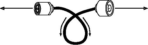
Figure
8.6: A drip loop forces
rainwater away from your
connectors.
Once
tight, connectors should be
protected by applying a layer of
electrical
tape,
then a layer of sealing
tape, and then another
layer of electrical tape
on
top.
The sealant protects the
connector from water
seepage, and the
tape
layer
protects the sealant from
ultraviolet (UV) damage.
Cables should have
an
extra drip loop to prevent
water from getting inside
the transceiver.
Safety
Always
use a harness securely
attached to the tower when
working at
heights.
If you have never worked on
a tower, hire a professional to do it
for
you.
Many countries require
special training for people
to be allowed to work
on
towers above a certain
height.
Avoid
working on towers during
strong winds or storms.
Always climb with a
partner,
and only when there is
plenty of light. Tower
work will likely
take
longer
than you think it will.
Remember that it is extremely
hazardous
to work
in
the dark. Give yourself
plenty of time to complete
the job long before
the
sun
sets. If you run out of
time, remember that the
tower will be there in
the
morning,
when you can start on
the problem again after a
good night s
sleep.
258
Chapter
8: Building an Outdoor
Node
Aligning
antennas on a long distance
link
To
properly align antennas at a
great distance, you will
need some sort of
visual
feedback that shows you
the instantaneous received
power at the an-
tenna
feed. This lets you to
make small changes to the
antenna alignment
while
watching the feedback tool,
ultimately stopping when the
maximum
received
power has been
found.
The
ideal antenna alignment
toolkit consists of a signal
generator and
a
spectrum
analyzer, preferably
one of each at both ends of
the link. By at-
taching
a signal generator to one
end of the link and a
spectrum analyzer to
the
other, you can observe
the received power and
watch the effect of
mov-
ing
the antenna to various
positions in real time. Once
the maximum has
been
found on one end of a point
to point link, the generator
and analyzer
can
be swapped, and the process
repeated for the other
end.
The
use of a signal generator is
preferable to using the
radio card itself, as
the
signal generator can
generate a continuous carrier. A
WiFi card transmits
many
discrete packets of information,
switching the transmitter on
and off
very
rapidly. This can be very
difficult to
find with a
spectrum analyzer,
par-
ticularly
when operating in noisy
areas.
Obviously,
the cost of a calibrated
signal generator and
spectrum analyzer
that
works at 2.4 GHz (or
even 5 GHz if using 802.11a)
is well beyond the
budget
of most projects. Fortunately
there are a number of
inexpensive tools
that
can be used instead.
Inexpensive
signal generator
There
are many inexpensive
transmitters that use the
2.4 GHz ISM band.
For
example, cordless phones,
baby monitors, and miniature
television
transmitters
all generate a continuous
signal at 2.4 GHz.
Television trans-
mitters
(sometimes called video
senders) are
particularly useful, since
they
often
include an external SMA
antenna connector and can be
powered by a
small
battery.
Video
senders usually include
support for three or four
channels. While these
do
not directly correspond to
WiFi channels, they permit
you to test the
low,
middle,
or high end of the
band.
For
5 GHz work, you can use a
video sender in combination
with a 2.4 GHz
to
5 GHz converter. These devices
accept a low power 2.4 GHz
signal and
emit
high power 5 GHz signals.
They are usually quite
expensive ($300-
$500
each) but will still
likely be cheaper than a 5 GHz
signal generator and
spectrum
analyzer.
Chapter
8: Building an Outdoor
Node
259
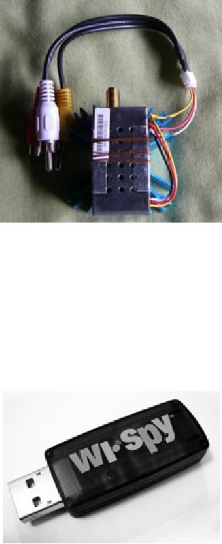
Figure
8.7: A 2.4 GHz video
sender with an SMA antenna
connector.
Whatever
you choose for a signal
source, you will need a
way to display the
received
power level levels at the
other end. While the
cost of 2.4 GHz
spec-
trum
analyzers is slowly coming
down, they still typically
cost a few thousand
dollars,
even for used
equipment.
Wi-Spy
The
Wi-Spy is a USB spectrum analysis
tool made by MetaGeek
(http://www.metageek.net/). It features
a very sensitive receiver in a
small
form
factor (about the size of a
USB thumb drive).
Figure
8.8: The Wi-Spy USB
spectrum analyzer
260
Chapter
8: Building an Outdoor
Node
The
latest version of the Wi-Spy
includes better dynamic
range and an exter-
nal
antenna connector. It also
comes with very good
spectrum analysis
soft-
ware
for Windows called
Chanalyzer. It provides instantaneous,
average,
maximum,
topographic, and spectral
views.
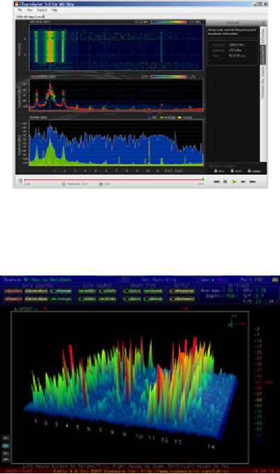
Figure
8.9: The distinctive spiked
pattern to the left of the
graph was caused by
a
high
power 2.4 GHz television
transmitter.
There
is an excellent free software package for
Mac OS X called EaKiu
(http://www.cookwareinc.com/EaKiu/). In addition to
the standard views, it
also
provides
an animated 3D view, and
adds support for multiple Wi-Spy
devices.
Figure
8.10: EaKiu's 3D view lets
you rotate and zoom in on
any part of the graph
in
real
time. There is probably a
WiFi network on channel 11,
with other noise
sources
lower
down in the band.
Chapter
8: Building an Outdoor
Node
261
For
Linux users, the Wi-Spy is
supported by the Kismet
Spectrum-Tools pro-
ject
(http://kismetwireless.net/spectools/). This
package includes
command
line
tools as well as a GUI built
on GTK.
Other
methods
Some
wireless routers (such as
the Mikrotik) provide an
"antenna alignment
tool"
that shows you a moving
bar representing the
received power. When
the
bar is at the maximum, the
antenna is aligned. With
some routers, you
can
also enable an audio
feedback mode. This causes
the router to emit a
loud
tone, changing the pitch
according to the received
power.
If
you don't have a spectrum
analyzer, Wi-Spy, or a device
that supports an
antenna
alignment mode, you will
need to use the operating
system to pro-
vide
feedback about the wireless
link quality. One simple
method to do this in
Linux
is with a loop that
continually calls iwconfig.
For example:
wildnet:~#
while :; do clear; iwconfig; sleep 1; done
This
will show the state of
all radio cards in the
system, updating once
every
second.
Note that this will
only work on the client
end of a link. On the
access
point
(master mode) side, you
should use the iwspy
command
to collect
statistics
for the MAC address of
the client:
wildnet:~#
iwspy ath0 00:15:6D:63:6C:3C
wildnet:~#
iwspy
ath0
Statistics
collected:
00:15:6D:63:6C:3C
: Quality=21/94 Signal=-74 dBm Noise=-95
dBm
Link/Cell/AP
:
Quality=19/94 Signal=-76 dBm Noise=-95
dBm
Typical/Reference
: Quality:0 Signal level:0 Noise level:0
You
can then use a while
loop
(as in the previous example)
to continually
update
the link status.
wildnet:~#
while :; do clear; iwspy; sleep 1;
done
Antenna
alignment procedure
The
key to successfully aligning
antennas on a very long
distance link is
communication.
If you change too many
variables at once (say, one
team
starts
wiggling an antenna while
the other tries to take a
signal strength read-
ing),
then the process will
take all day and
will probably end with
misaligned
antennas.
You
will have two teams of
people. Ideally, each team
should have at least
two
people: one to take signal
readings and communicate
with the remote
end,
the other to manipulate the
antenna. Keep these points
in mind while
working
on long distance
links.
262
Chapter
8: Building an Outdoor
Node
1.
Test
all equipment ahead of time.
You
don t
want to
fiddle
with settings
once
you re in the
field.
Before separating the
equipment, power
every-
thing
on, connect every antenna
and pigtail, and make
sure you can
es-
tablish
a connection between the
devices. You should be able
to return
to
this known good state by
simply powering on the
device, without hav-
ing
to log in or change any
settings. Now is a good time
to agree on an-
tenna
polarization (see Chapter
2 if
you don t
understand
what polariza-
tion
means).
2.
Bring
backup communications gear. While
mobile phones are
usually
good
enough for working in
cities, mobile reception can
be bad or nonex-
istent
in rural areas. Bring a high
powered FRS or GMRS radio,
or if
your
teams have amateur radio
licenses, use a ham rig.
Working at a
distance
can be very frustrating if
you are constantly asking
the other
team
"can you hear me now?"
Pick your communication
channels and
test
your radios (including the
batteries) before
separating.
3.
Bring a
camera. Take
some time to document the
location of each
site,
including
surrounding landmarks and
obstructions. This can be
very use-
ful
later to determine the
feasibility of another link to
the location without
having
to travel there in person. If
this is your first
trip to the site, log
the
GPS
coordinates and elevation as
well.
4.
Start by
estimating the proper bearing and
elevation. To begin,
both
teams
should use triangulation
(using GPS coordinates or a
map) to get
a
rough idea of the direction
to point. Use a compass to
roughly align
the
antenna to the desired
bearing. Large landmarks are
also useful for
pointing.
If you can use binoculars to
see the other end,
all the better.
Once
you have made your
guess, take a signal
strength reading. If
you
are
close enough and have
made a good guess, you
may already have
signal.
5.
If all
else fails, build your own
landmark. Some
kinds of terrain make
it
difficult
to judge the location of the
other end of a link. If you
are building a
link
in an area with few
landmarks, a self-made landmark
such as a kite,
balloon,
flood light, flare, or even
smoke signal might help.
You don t
nec-
essarily
need a GPS to get an idea of
where to point your
antenna.
6.
Test
signal in both directions, but
only one at a time. Once
both
ends
have made their best
guess, the end with
the lowest gain
antenna
should
make fix their
antenna into position. Using
a good monitoring
tool
(such
as Kismet, Netstumbler, or a good
built-in wireless client),
the team
with
the highest gain antenna
should slowly sweep it
horizontally while
watching
the signal meter. Once
the best position is found,
try altering
the
elevation of the antenna.
After the best possible
position is found,
lock
the antenna firmly
into place and signal
the other team to
begin
slowly
sweeping around. Repeat this
process a couple of times
until the
best
possible position for both
antennas is found.
Chapter
8: Building an Outdoor
Node
263
7.
Don
t
touch
the antenna when taking a reading.
Your
body will affect
the
radiation pattern of the
antenna. Do not touch the
antenna, and don t
stand
in the path of the shot,
when taking signal strength
readings. The
same
goes for the team on
the other side of the
link, too.
8.
Don
t
be
afraid to push past the best
received signal. As we saw
in
chapter
four, radiation patterns
incorporate many smaller
sidelobes of
sensitivity,
in addition to a much larger
main lobe. If your received
signal
is
mysteriously small, you may
have found a sidelobe.
Continue sweep-
ing
slowly beyond that lobe to
see if you can find the
main lobe.
9.
The
antenna angle may look completely
wrong. The
main lobe of an
antenna
often radiates slightly to
one side or the other of
the visual dead
center
of the antenna. Offset feed
dishes will seem to be
pointing too far
down,
or even directly at the
ground. Don t
worry
about how the
antenna
looks;
you are concerned with
finding
the best possible position
to
achieve
the greatest possible
received signal.
10.
Double-check
polarization. It can be
frustrating to attempt aligning
a
dish
only to discover that the
other team is using the
opposite polariza-
tion.
Again, this should be agreed
upon before leaving home
base, but if
a
link stays stubbornly weak,
a double check doesn t
hurt.
11.
If nothing
works, check all components
one at a time. Are
the devices
on
both ends of the link
powered on? Are all
pigtails and connectors
prop-
erly
connected, with no damaged or
suspect parts? As outlined in
chapter
eight,
proper troubleshooting technique
will save you time
and frustration.
Work
slowly and communicate your
status well with the
other team.
By
working methodically and
communicating well, you can
complete the job
of
aligning high gain antennas
in just a short while. If
done properly, it
should
be
fun!
Surge
and lightning protection
Power
is the greatest challenge
for most installations in
the developing world.
Where
there are electrical
networks, they are often
poorly controlled, fluctu-
ate
dramatically and are
susceptible to lightning. Proper
surge protection is
critical
to not only protect your
wireless equipment, but all
of the equipment
connected
to it.
Fuses
and circuit breakers
Fuses
are critical, but very
often neglected. In rural
areas, and even in
many
urban
areas of developing countries,
fuses are difficult to
find.
Despite the
added
cost, it is always prudent to
use circuit breakers
instead. These may
need
to be imported, but shouldn't be
overlooked. Too often,
replaceable
264
Chapter
8: Building an Outdoor
Node
fuses
are removed and pocket
change is used instead. In a
recent case, all
of
the electronic equipment at at
rural radio station was
destroyed when a
lightning
strike went through the
circuit, without circuit
breaker or even a
fuse
to
protect it.
How
to ground
Proper
grounding doesn t
have to be a
complicated job. When
grounding,
you
are trying to accomplish two
things: provide a short-circuit
for a lightning
strike,
and provide a circuit for
excess energy to be
dissipated.
The
first
step is to protect equipment
from a direct or near direct
lightning hit,
while
the second provides a path
to dissipate excess energy
that would oth-
erwise
cause a build-up of static
electricity. Static can
cause significant
deg-
radation
to signal quality, particularly on
sensitive receivers (VSATs
for ex-
ample).
Providing the short-circuit is
simple. The installer simply
needs to
make
the shortest path from
the highest conductive
surface (a lightning
rod)
to
the ground. When a strike
hits the rod, the
energy will travel the
shortest
path
and thus by-pass the
equipment. This ground
should be able to
handle
high-voltage
(i.e. you need thick
gauge wire, like 8 gauge
braided copper).
To
ground the equipment, mount
a lightning rod above the
equipment on a
tower
or other structure. Then use
a thick gauge conductive
wire to connect
the
rod to something that itself
is well grounded. Underground
copper pipes
can
be very well grounded
(depending on their depth,
the moisture,
salinity,
amount
of metal and organic content
of the soil). In many sites
in West Af-
rica,
pipes aren t
yet in
the ground, and previous
grounding equipment is
of-
ten
inadequate due to ill-conductive
soil (typical of seasonally
arid, tropical
soils).
There are three easy
ways to measure the efficiency of
your ground:
1.
The least accurate is to
simply plug a good quality
UPS or power strip
into
the circuit that has a
ground detect indicator (a
LED light). This
LED
is
lit by energy that is being
diffused to the ground
circuit. An effective
ground
will dissipate small amounts
of energy to the ground.
Some peo-
ple
actually use this to pirate
a bit of free light, as this
energy does not
turn
an electrical counter!
2.
Take a light socket and a
low-wattage bulb (30 Watts),
connect one wire
to
the ground wire and
the second to the hot
wire. If the ground is
work-
ing,
the bulb should shine
slightly.
3.
The more sophisticated way
is to simply measure the
impedance be-
tween
the positive circuit and
the ground.
If
your ground is not efficient
you will need to bury a
grounding stake
deeper
(where
the soil is more moist,
has more organic matter
and metals) or you
need
to make the ground more
conductive. A common approach
where there
Chapter
8: Building an Outdoor
Node
265
is
little soil is to dig a hole
that is 1 meter in diameter
and 2 meters deep.
Drop
in a highly conductive piece of
metal that has some
mass to it. This is
sometimes
called a plomb, which
literally means lead but
can be any heavy
piece
of metal weighing 50 kg or more,
such as an iron anvil or
steel wheel.
Then
fill the
hole with charcoal and
mix in salt, then top
with soil. Soak
the
area,
and the charcoal and
salt will diffuse around
the hole and make a
con-
ductive
area surrounding your plomb,
improving the efficiency of
the ground.
If
radio cable is being used,
it too can be used to ground
the tower, though a
more
resilient design is to separate
the ground for the
tower from the
cable.
To
ground the cable, simply
peel back a bit of cable at
the point closest to
the
ground
before it goes into the
building, then attach a
ground cable from
that
point,
either by soldering or using a
very conductive connector.
This then
needs
to be waterproofed.
Power
stabilizers & regulators
There
are many brands of power
stabilizers, but most are
either digital or
electromechanical.
The latter are much
cheaper and more common.
Elec-
tromechanical
stabilizers take power at
220V, 240V, or 110V and
use that
energy
to turn a motor, which
always produces the desired
voltage (nor-
mally
220V). This is normally
effective, but these units
offer little
protection
from
lightning or other heavy
surges. They often burn
out after just
one
strike.
Once burnt, they can
actually be fused at a certain
(usually wrong)
output
voltage.
Digital
regulators regulate the
energy using resistors and
other solid state
components.
They are more expensive,
but are much less
susceptible to
being
burnt.
Whenever
possible, use a digital
regulator. They are worth
the added cost,
and
will offer better protection
for the rest of your
equipment. Be sure to
in-
spect
all components of your power
system (including the
stabilizer) after
lightning
activity.
Table of Contents:
- Where to Begin:Purpose of this book, Fitting wireless into your existing network, Wireless networking protocols
- A Practical Introduction to Radio Physics:What is a wave?, Polarization
- Network Design:Designing the physical network, Mesh networking with OLSR, Estimating capacity
- Antennas & Transmission Lines:Cables, Waveguides, Connectors and adapters, Amplifiers
- Networking Hardware:Wired wireless, Choosing wireless components, Building an access point from a PC
- Security & Monitoring:Physical security, Threats to the network, Authentication
- Solar Power:Solar energy, Photovoltaic system components, The battery
- Building an Outdoor Node:Waterproof enclosures, Providing power, Mounting considerations
- Troubleshooting:Building your team, Proper troubleshooting technique, Common network problems
- Economic Sustainability:Create a Mission Statement, Evaluate the Demand for Potential Offerings
- Case Studies:General advice, Crossing the divide with a simple bridge in Timbuktu, Networking Mérida State
- Appendix A: Resources:Antennas and antenna design, Security
- Appendix B: Channel Allocations
- Appendix C: Path Loss
- Appendix D: Cable Sizes
- Appendix E: Solar Dimensioning:General Data, Component Characteristics
- Glossary